Wallbox PULSAR User manual

PULSAR
Service Manual

INDEX
3
4
5
5
6
7
7
8
9
9
11
13
13
15
17
Important Information
Required Materials
Plastic Cover Replacement
Removing the Old plastic cover
Attaching the New plastic cover
Control board and Plastic Cover Replacement
Removing the Old Control board and the Plastic cover
Attaching the New Control board and the Plastic cover
Power board Replacement
Removing the Old Power Board
Attaching the New Power Board
Power Supply Unit
Removing the old Power Supply Unit
Attaching the new Power Supply Unit
Service

3
Introduction and Scope
Safety Recommendations
Legal Notice
Safety and Maintenance Instructions
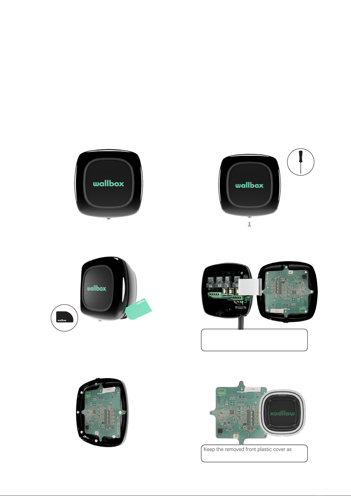
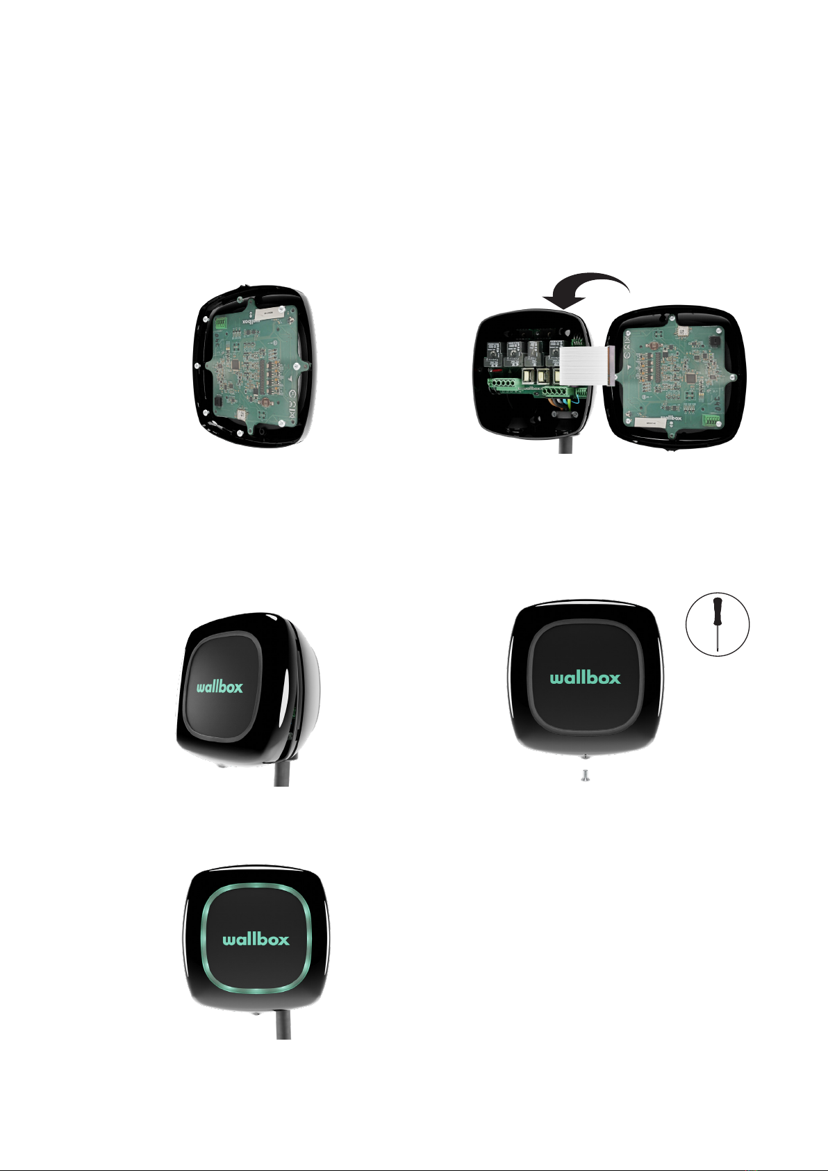
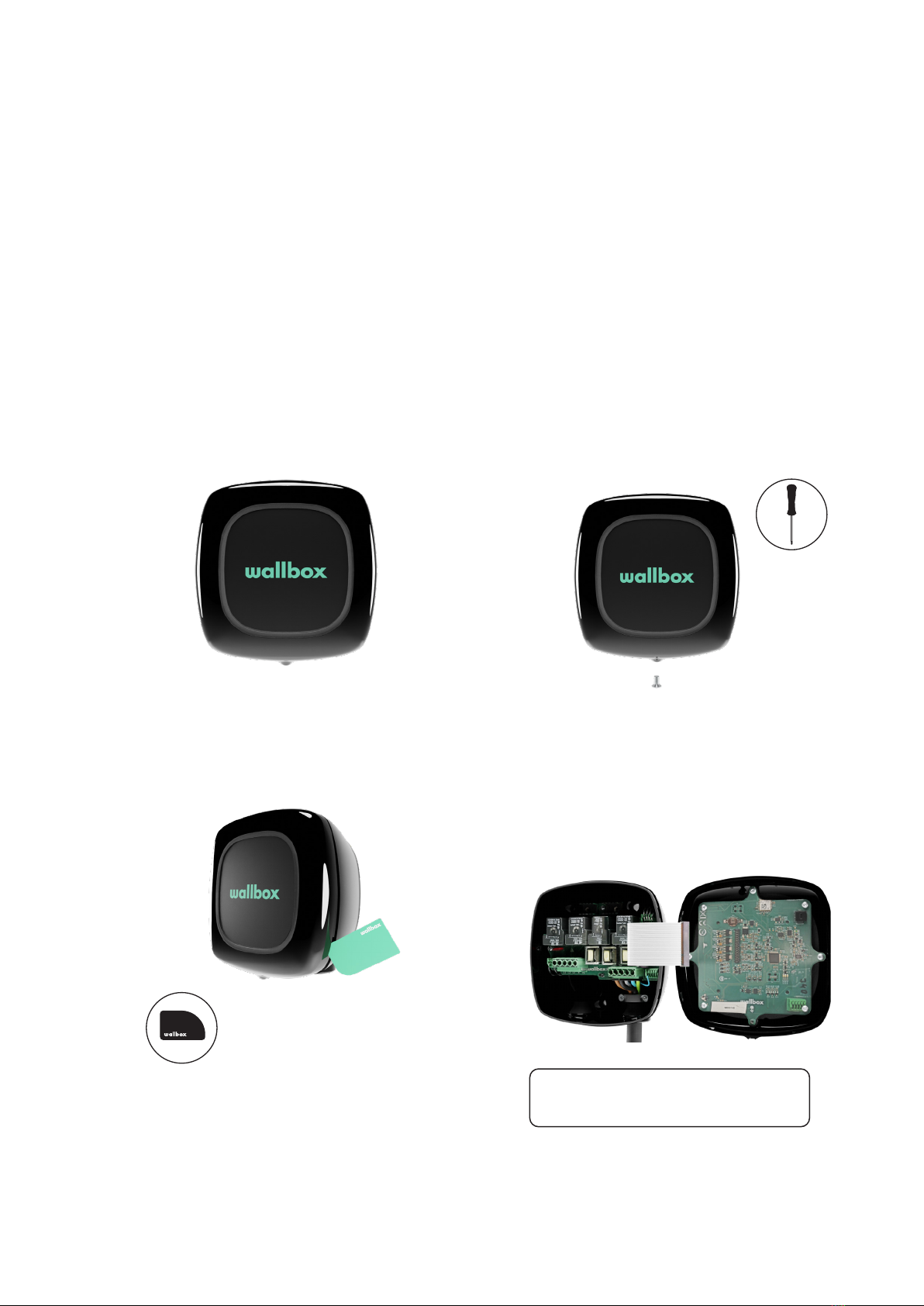
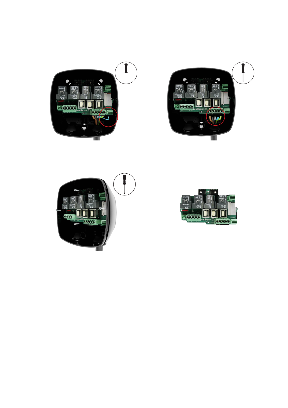
The purpose of this document is to describe the process of replacing service parts of the Pulsar
charger’s hardware system.
Intent of this service manual is to lend a hand to our service partners in replacing the service parts.
This document enlists step by step procedures along with graphical description of the replacement
procedure for various hardware parts.
• Wallbox warrants this product against defects in materials and workmanship for a period of 2 years
from the date of purchase. • During this period, at its discretion, Wallbox will either repair or replace
any defective product at no charge to the owner. • Replacement products or repaired parts will be
guaranteed for only the unexpired portion of the original warranty or six months whichever is greater.
• Any defect resulting from any accident, misuse, improper maintenance, or normal wear and tear is
not covered by the limited warranty. • Substitution or incorporation of any part by the client will be
considered as incorrect usage. • Except to the extent permitted by applicable law, the terms of this
limited warranty do not exclude, restrict, or modify, and are in addition to, the mandatory statutory rights
applicable to the sale of the product to you. If you believe your product is defective, contact Wallbox for
instructions on where to send or bring it for repair. EN Disposal Advice In accordance to the directive
2012/19/EC, at the end of its useful life, the product should not be disposed o as urban waste. It should
be taken to a collection center or a distributor that provides disposal of special and dierentiated waste.
• Follow all the safety instructions carefully. Failure to follow instructions may be a safety hazard and/or
cause equipment malfunction.
• Any resulting damage due to disregard or actions contrary to the instructions in this manual is
excluded from the product warranty.
• Any information in this manual may be changed without prior notice and does not represent any
obligation on the part of the manufacturer.
• Images in this manual are for illustration purposes only and might dier from the delivered product.
• Installation, maintenance, & servicing of the charger must be performed only by qualified personnel
per the applicable local regulations.
• Unauthorized installation and, servicing, and modifications make the manufacturer warranty void.
• Power o the charger before opening the cover or cleaning the unit.
• Do not use cleaning solvents on any part of the charger. Use a clean, dry cloth to remove dust and
dirt.
• Do not open the cover in rain.
Important InformationImportant Information

4
Required Materials
Torx T9
Screwdriver
Pulsar
opening tool
Star
Screwdriver
Spare part to be replaced:
Control board + Cover,
Power board, Power Supply Unit

5
Carefully remove the communications cable
from the front plastic cover of the charger.
Ensure that the communications cable is detached
gently from the connector. Do not pull or apply
excessive force to remove the cable.
Keep the removed front plastic cover aside for
safe disposal.
Using the opening tool, unclip the cover from
the charger’s body.
3. 4.
Removing the old plastic cover
Unscrew the Torx screw at the bottom of
the charger using a Torx T9 screwdriver and
save it for later use.
Turn o the power supply to the charger.
1. 2.
Plastic Cover Replacement
The front plastic cover of Pulsar is replaceable if damaged. The front plastic cover encloses the control
board. However, if the control board is working properly, only the front plastic cover shall be replaced.
Unscrew the outer 12 screws that hold the
Control board and the LED Halo with the
front plastic cover and save them for later. Keep the control board and the LED Halo
aside for later use.
5.
6.

6
3. 4.
Connect the ribbon cable to the connector
on the Control board and close the charger.
Place the Control board and the LED Halo on
the new front plastic cover and screw the 12
screws that were removed while detaching the
control board and LED Halo from the cover.
1. 2.
Attaching the new plastic cover
Insert and then tighten the Torx screw in the
bottom of the charger to secure the front
plastic cover and restore the power supply to
the charger.
Position the top clip points of the cover on
the charger body. Clip first the lateral clips to
the charger body and then the bottom clips.
Restore the power supply to the charger.
5.

7
Control board and Plastic Cover Replacement
The Control board of the Pulsar charger is enclosed within the front plastic cover and LED Halo of the
charger.
The Control board and front plastic cover of the Pulsar charger, if malfunctioning or damaged can be
replaced by performing the following steps:
Unscrew the Torx screw at the bottom of
the charger using a Torx T9 screwdriver and
save it for later use.
Carefully remove the communications cable
from the front plastic cover and body of the
charger.
Keep the old Control board aside for return or
disposal.
Turn o the power supply to the charger.
Using the opening tool, unclip the cover from
the charger´s body.
1.
3.
2.
4.
Removing the old Control board and the plastic cover
Ensure that the communications cable is detached
gently from the connector. Do not pull or apply
excessive force to remove the cable.

8
Place the sticker with the new Serial Number
on top of the old sticker.
Position the top clip points of the cover on
the charger body. Clip first the lateral clips to
the charger body and then the bottom clips.
2.
3. Insert and then tighten the Torx screw in the
bottom of the charger to secure the front
plastic cover.
Restore the power supply to the charger.
4.
5.
Attaching the new Control board and the Plastic cover
Carefully attach the communications cable to
the connector on the Control board and close
the charger.
1.

9
Power Board Replacement
The Power board of the Pulsar charger is enclosed within the plastic body of the charger. The Power
board, if malfunctioning or damaged can be replaced by performing the following steps:
Removing the old Power board
Unscrew the Torx screw at the bottom of
the charger using a Torx T9 screwdriver and
save it for later use.
Carefully remove the communications cable
from the body of the charger.
Turn o the power supply to the charger.
Using the opening tool, unclip the cover from
the charger´s body.
1.
3.
2.
4.
Ensure that the communications cable is detached
gently from the connector. Do not pull or apply
excessive force to remove the cable.
Using a screwdriver remove the power input
cables.
Remove the cables that are connected to
the Power Supply unit. Use a screwdriver to
release the cables from the connectors
5. 6.
Ensure to remember the right configuration of cables
with their respective levers. If it helps, note down the
configuration on a piece of paper for your reference.

10
Keep the old Power board aside for return or
disposal.
Unscrew the four screws that hold the Power
board to the body of the charger. Save them
for later use.
9. 10.
Using a screwdriver remove the power output
cables.
Using a screwdriver remove the control pilot
cable from the connector.
7. 8.

11
Insert the cables that are connected to the
Power Supply unit. Use a screwdriver to press
the connector levers and then insert the
cable.
Get the front plastic cover and connect the
communications cable to the Power board.
Insert the control pilot cable in the connector
by pressing the connector levers with a
screwdriver and then insert the cable.
Insert the power input cables in their
connectors and tighten the screws one by
one in a sorted fashion.
3.
5.
4.
6.
Attaching the new Power board
Insert and tighten the four screws to secure the Power
board to the charger’s body.
1. 2.
Insert the power output cables in their connectors
and tighten the screws one by one in a sorted
manner.
Check that the power input cables are fixed properly.

12
Position the top clip points of the front
plastic cover on the charger’s body. Clip first
the lateral clips to the charger’s body and
then the bottom clips. Make sure the 8 clips
are properly placed.
7.
Restore the power supply to the charger.
Insert and then tighten the Torx screw in the
bottom of the charger to secure the front
plastic cover.
8.
9.

13
Power Supply Unit
The Power Supply unit for Pulsar can be replaced if damaged. The Power Supply unit is enclosed within
the charger’s body and connected to the Power board.
Unscrew the Torx screw at the bottom of
the charger using a Torx T9 screwdriver and
save it for later use.
Carefully remove the communications cable
from the body of the charger.
Turn o the power supply to the charger.
Using the opening tool, unclip the cover from
the charger’s body.
1.
3.
2.
4.
Ensure that the communications cable is detached
gently from connector. Do not pull or apply excessive
force to remove the cable.
Removing the old Power Supply Unit
Remove the cables that are connected to
the Power Supply unit. Use a screwdriver to
release the cables from the connectors
Using a screwdriver remove the power input
and output cables.
5. 6.

14
Keep the Power Supply Unit aside for return
or disposal.
Unscrew the four screws that hold the Power
Supply unit to the Body
9. 10.
Unscrew the four screws that hold the power
board to the body of the charger. Save them
for later use.
Using a screwdriver remove the control pilot
cable from the connector.
7. 8.
Keep the Power board aside.

15
Insert the power output cables in their
connectors and tighten the screws one by
one in a sorted manner.
Place the Power board on the charger’s
body and secure it to the chargers body by
tightening the four screws.
3. 4.
Attaching the new Power Supply Unit
Get the new Power Supply unit and place it in on the
charger’s body.
1. 2.
Insert and tighten the four screws to secure the
Power Supply unit to the charger’s body.
Insert the cables that are connected to the
Power Supply unit. Use a screwdriver to press
the connector levers and then insert the
cable.
Insert the control pilot cable in the connector
by pressing the connector levers with a
screwdriver and then insert the cable.
5. 6.

16
Insert the power input cables in their
connectors and tighten the screws one by
one in a sorted manner.
Get the front plastic cover and connect the
communications cable to the Power board.
7. 8.
Restore the power supply to the charger.
Insert and then tighten the Torx screw in the
bottom of the charger to secure the front
plastic cover.
10.
11.
Position the top clip points of the front plastic
cover on the charger’s body. Clip first the
lateral clips to the charger´s body and then
the bottom clips. Make sure the 8 clips are
properly placed.
9.
Check that the power input cables are fixed properly.

17
ServiceService
Need more assistance? You can reach out to us:
België/Belgique
+32 2 808 88 28
+45 89 87 87 15
+49 69 96759775
+34 932 20 95 75
Danmark
Deutschland
España
France
+33 1 76 46 09 15
+353 14 854 347
+39 011 1962 2461
+31 20 808 0847
Ireland
Italia
Nederland
Norge
+47 51 74 20 00
+351 308 801 440
+43 720882116
Portugal
Österreich
Schweiz/Suisse
+41 43 508 06 75
+46 852503203
+44 20 3318 3779
Sverige
United Kingdom
Other manuals for PULSAR
9
Table of contents
Other Wallbox Automobile Batteries Charger manuals
Popular Automobile Batteries Charger manuals by other brands

Charge Amps
Charge Amps Beam user manual

Club Car
Club Car PowerDrive owner's manual

Schumacher Electric
Schumacher Electric BATTERY EXTENDER BE01252 owner's manual

EVBox
EVBox Audi Wallbox Installation and user manual

Jackson
Jackson SUPERCHARGER with PowerCard installation instructions

ULTIMATE SPEED
ULTIMATE SPEED ULG 3.8 B1 operating instructions