© PORTTechnologyby Schindler Ltd -Oct20, 2017
RFID Reader for PORT
PCR-TWN4
Contents
1
Introduction
......................................................................................................................................
2
Scope
...............................................................................................................................................
3
Compatibility
....................................................................................................................................
3
General overview
............................................................................................................................
3
References
......................................................................................................................................
3
2
General board implementation
......................................................................................................
4
Block schematic
..............................................................................................................................
4
Functionality
....................................................................................................................................
4
USB and Power supply
..................................................................................................................
4
TWN4 module
.................................................................................................................................
5
radio
..................................................................................................................................................
6
HF antenna
......................................................................................................................................
6
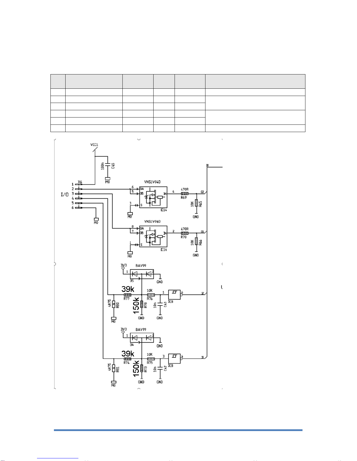
Input/Output
.....................................................................................................................................
7
Wiegand output
...............................................................................................................................
8
K-LC1A radar interface
..................................................................................................................
8
JRC radar interface
......................................................................................................................
10
RGB LEDs
.....................................................................................................................................
11
SAM sockets
.................................................................................................................................
11
3
Mechanics
......................................................................................................................................
12
4
Reliability
........................................................................................................................................
13
EMC
................................................................................................................................................
13
Climatic conditions
.......................................................................................................................
13
Certifications
..................................................................................................................................
13
5
Document History
..........................................................................................................................
14
6
Appendix
.........................................................................................................................................
15