Portable Winch 600MH User manual

© 2020 Portable Winch Co. - All Rights Reserved - Printed in Canada
WICHTIG:
Vor Gebrauch
lesen
IMPORTANT:
Read before
using
IMPORTANTE:
Lea antes de
usar
IMPORTANT:
Lire avant
usage
IMPORTANT:
leggere prima
dell'uso
BELANGRIJK:
lees voor
gebruik
VIKTIG:
Les før du
bruker
VIKTIGT:
Läs innan du
använder
DE Betriebs-/Sicherheitshinweise
EN
Operating/safety Instructions
ES Instrucciones de operación / seguridad
FR Consignes de fonctionnement/sécurité
I T Istruzioni per l'uso e la sicurezza
NL Gebruiksaanwijzing / Veiligheidsvoorschriften
NO
Bruksanvisning / sikkerhet
SV Bruksanvisning / säkerhet
www.600mh.com
WICHTIG:
Vor Gebrauch
lesen
IMPORTANT:
Read before
using
IMPORTANTE:
Lea antes de
usar
IMPORTANT:
Lire avant
usage
IMPORTANT:
leggere prima
dell'uso
BELANGRIJK:
lees voor
gebruik
VIKTIG:
Les før du
bruker
VIKTIGT:
Läs innan du
använder
USER GUIDE
CABLE LAYING MACHINE
MACHINE À FILS
KABELVERLEGUNGSMASCHINE

2
THE ORIGINAL LANGUAGE
OF THIS DOCUMENT IS FRENCH
INTRODUCTION
Portable Winch Co. wishes to thank you for purchasing a Perimeter
Wire Machine 600MHTM. This manual was written to help you make the
best use of your new machine and to use it in the most secure way.
PLEASE READ CAREFULLY BEFORE USE
For any problems or questions, please contact an authorized Portable
Winch Co. dealer or contact us directly.
1 Safety guidelines
The Perimeter Wire Machine 600MHTM is designed to bury electrical
wires up to 6 mm in diameter at a depth of between 4 and 6 cm in
grassy soil. The use of this machine implies serious risks of injury,
property damage or even death. Do not underestimate its potential
danger.
1.1 Safety messages
Your safety and the safety of others are very important. You will
find important safety messages in this manual. Please read them
carefully.
These security messages warn you of potential injuries to either
yourself or others. Each safety message is preceded by a warning
symbol.
1.2 Label
1.2.1 Serial number label
The serial number label can be found on the right rear of the
machine. In addition to the serial number, the fundamental
specifications of your model are also found there
1.2.2 Personal protection equipment label
The label indicates that it is highly recommended to
wear the following:
• Safety glasses with deflectors • Hearing protection;
• Anti-vibration gloves • Steel toe-capped shoes.
1.2.3 Read the user manual label
The read the user manual label indicates that it is
necessary to read the entirety of this manual before
using the machine.
1.2.4 Warning label for potential dangers of
the blade
This warning label informs you of the following
potential dangers:
●Debris can fly out and cause injuries to the
eyes;
●The blade can crush feet;
●The blade can crush hands;
●The blade can cut hands.
1.2.5 Warning label for slope usage
The warning label for slope usage indicates that
the machine must not be used on slopes steeper
than 50%.
1.2.6 Safety information
BEFORE STARTING ANY PERIMETER WIRE LAYING WORK,
MAKE SURE YOU KNOW THE LOCATIONS OF ANY
ELECTRICAL WIRES OR WATER PIPES IN THE WORK ZONE.
THE MACHINE WEIGHS 36 KG. BE CAREFUL WHEN TRYING
TO LIFT IT. IT IS HIGHLY RECOMMENDED TO LIFT IT WITH A
SECOND PERSON.
NEVER LET AN UNTRAINED PERSON USE THE MACHINE.
MAKE SURE THAT THEY ARE AWARE OF THE SAFETY AND
USAGE INSTRUCTIONS AND HAVE READ THIS MANUAL.
ONLY RESPONSIBLE ADULTS WHO HAVE READ THESE
INSTRUCTIONS ARE AUTHORISED TO OPERATE THE
MACHINE. DO NOT ALLOW CHILDREN TO OPERATE IT.
KEEP CHILDREN, SPECTATORS AND ANIMALS OUTSIDE OF
THE WORK ZONE. STOP THE MACHINE IN SOMEONE
ENTERS THE WORK ZONE.
DO NOT PLACE YOUR FEET NEAR THE BLADE WHILE THE
ENGINE IS RUNNING.
ENSURE THAT YOUR CLOTHING CANNOT GET CAUGHT
IN THE MOVING PARTS OF THE MACHINE.
CLEAN AND/OR REPLACE ALL SECURITY LABELS THAT ARE
DIRTY, DETERIORATED, UNREADABLE OR TORN.
SYMBOLE SIGNIFICATION
YOU WILL BE FATALLY OR SERIOUSLY
INJURED IF YOU DO NOT FOLLOW THESE
INSTRUCTIONS.
YOU COULD BE FATALLY OR SERIOUSLY
INJURED IF YOU DO NOT FOLLOW THESE
INSTRUCTIONS.
YOU COULD BE INJURED IF YOU DO
NOT FOLLOW THESE INSTRUCTIONS.
READ THE USER GUIDE.
EYE AND HEARING PROTECTION.
WEAR GLOVES.
44-0042
EN

EN
3
± 0°
ALWAYS WEAR SAFETY GLASSES WITH DEFLECTORS WHEN
USING THE MACHINE.
ALWAYS WEAR GLOVES WHEN USING THE MACHINE.
ALWAYS WEAR HEARING PROTECTION WHEN USING THE
MACHINE.
ALWAYS WEAR STEEL TOE-CAPPED SHOES WHEN USING
THE MACHINE.
DO NOT BACK UP THE MACHINE UNLESS ABSOLUTELY
NECESSARY. ALWAYS CHECK THE GROUND AND BEHIND
YOU BEFORE MOVING.
CLEAR THE WORK ZONE OF OBJECTS SUCH AS SMALL
STONES, TOYS, METAL WIRES, STICKS, ETC. THEY CAN BE
CUT AND/OR LIFTED AND PROJECTED BY THE BLADE.
NEVER USE THE MACHINE IF THE PROTECTION GUARDS
AND OTHER SAFETY DEVICES ARE NOT IN PLACE.
STOP THE ENGINE WHEN CROSSING DRIVEWAYS,
SIDEWALKS OR STREETS.
DO NOT USE THE MACHINE IF YOU ARE UNDER THE
INFLUENCE OF ALCOHOL OR DRUGS.
NEVER USE THE MACHINE ON WET GRASS. WALK AT A
STEADY PACE, HOLD ON TO THE HANDLE AND WALK
NEVER RUN.
IF THE MACHINE STARTS TO VIBRATE ABNORMALLY, STOP
THE ENGINE AND CHECK IMMEDIATELY FOR THE CAUSE.
STRONG VIBRATIONS ARE USUALLY A SIGN SOMETHING IS WRONG
STOP THE ENGINE BEFORE CLEANING, INSPECTION OR
REPAIRS.
BOLTS AND NUTS, ESPECIALLY THE BOLTS USED TO ATTACH
THE BLADE SHOULD ALWAYS BE PROPERLY TIGHTENED.
KEEP THE MACHINE IN GOOD CONDITION.
NEVER TAMPER WITH SAFETY DEVICES. REGULARLY CHECK
THEY ARE WORKING PROPERLY.
KEEP GRASS, LEAVES OR DEBRIS OF ANY KIND FROM
ACCUMULATING ON THE MACHINE OR IN FRONT OF THE
BLADE. CLEAN OIL OR FUEL SPILLAGES.
ALLOW THE MACHINE TO COOL BEFORE STORING IT.
IF YOU HIT AN OBJECT, STOP THE MACHINE AND CHECK
FOR DAMAGE. BEFORE RESTARTING, REPAIR THE DAMAGE
IF NECESSARY.
THE MACHINE'S BLADE CAN CUT. WRAP THE BLADE OR
WEAR GLOVES AND BE CAREFUL WHEN PERFORMING
MAINTENANCE ON THE BLADE.
2. Checks before use
2.1 When receiving
Inspect the box to detect any obvious damage. If a part is missing or
damaged, notify the carrier immediately. Please refer to the
assembly manual for the contents of your machine.
2.2 Assembly and start-up
2.2.1 Assembly
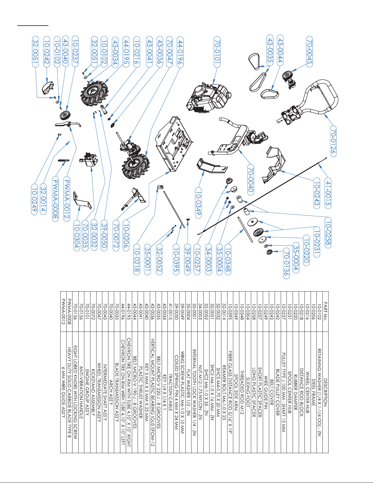
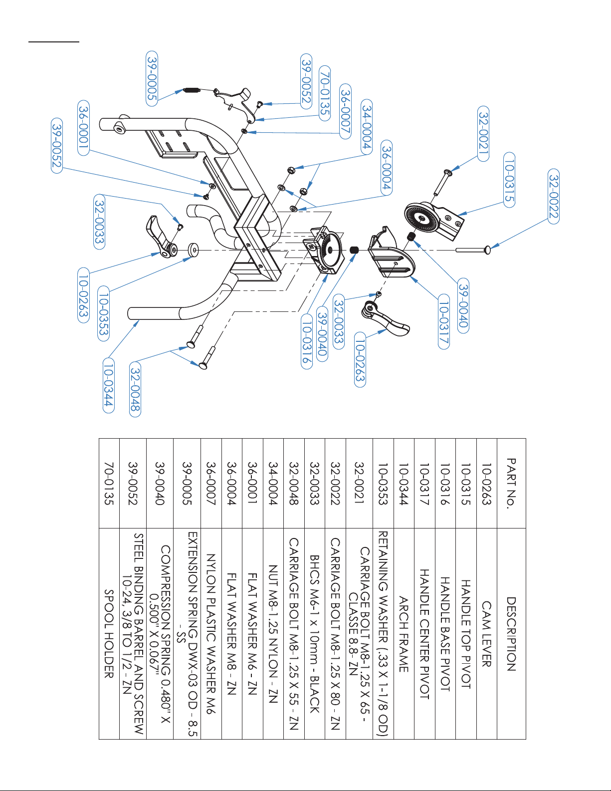
The Perimeter Wire Machine 600MHTM was completely assembled
at the factory except for the following parts:
blade, wire guide, sliding foot, blade pulley
cover, wheels and handle. To ensure safe and
appropriate operation, these parts must be
attached securely. Use the appropriate
wrench to ensure they are tightened sufficiently.
To assemble the components mentioned
above, please follow the instructions in the
600MH ASSEMBLY MANUAL.
IT IS ESSENTIAL THAT ALL OF
THE STEPS ARE CARRIED
OUT
2.2.2 Start-up – Preparation and start-up of the engine
Perimeter wire machine 600MHTM is equipped with a four-stroke
GXH-50cc Honda engine.
2.2.2.1 Engine Oil
2.2.2.2 Gasoline(petrol)
IMPORTANT: Fill the tank with the machine resting on the
support foot to avoid overfilling.
Fill the tank with UNLEADED gasoline. Do not use an oil/gasoline
mixture. This machine is equipped with a four-stroke engine. Consult
the Honda engine manual for more information.
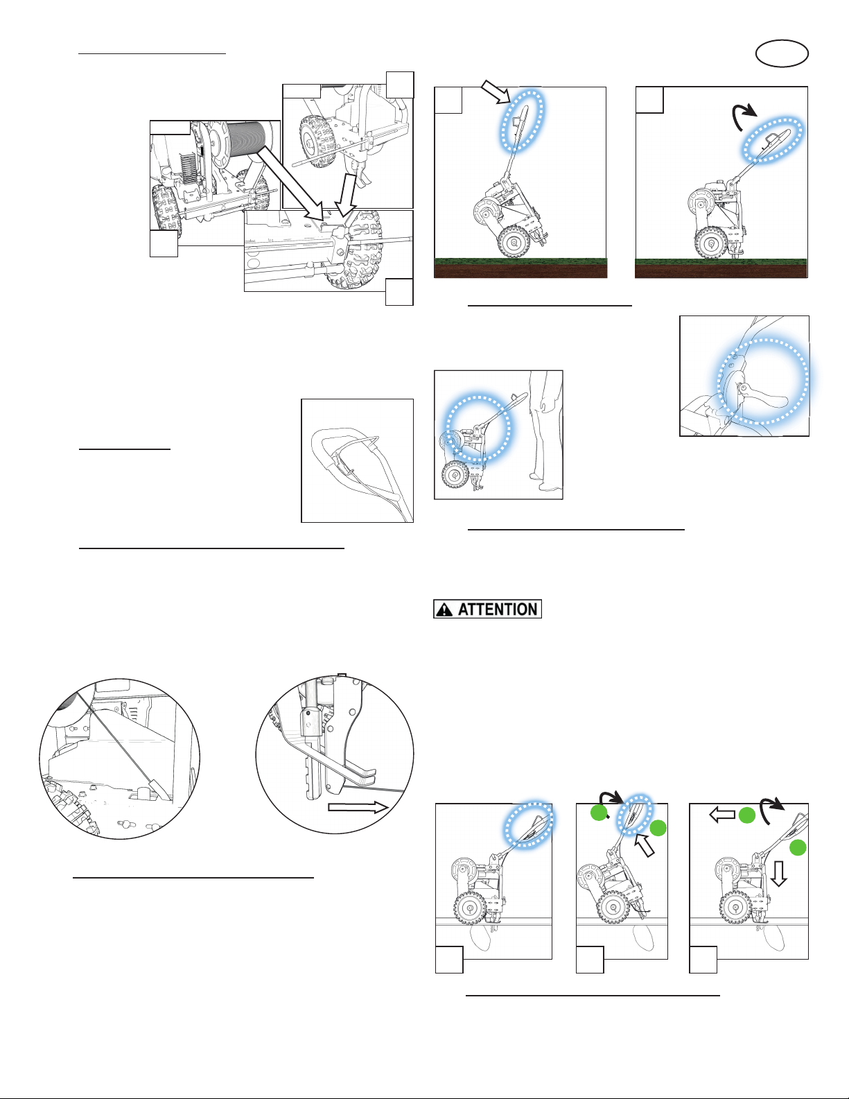
2.2.2.3 First use
Consult the Honda
engine manual for
starting instructions.
The on/off switch is
located on the
engine.
Take care to pull the
starter grip in the
output axis of the
rope. If it is pulled
vertically, the friction of the rope on the plastic housing may damage
the rope and/or the housing (see Figures).
IMPORTANT: Let the engine idle for five (5) minutes.
2.2.3 Oil level warning system (Oil AlertTM)
The Honda engine GXH-50 is equipped with the Oil AlertTM system
that automatically cuts the ignition when the oil level in the crankcase
falls below a safe level. The Oil AlertTM system also stops the engine
when the engine’s operating angle exceeds 20 degrees (± 4 degrees).
Check the oil level before each use. Add oil if necessary.
Fill the Honda engine with a maximum
of 0.25 liters of SAE 10W-30 API SJ oil.
For special uses and in extreme
temperature conditions, consult the
Honda engine manual.
Follow these instructions to make sure
that the engine receives the correct
quantity of oil.
1. Position the machine so that the
engine is level (Figure 1);
2. Fill the crankcase (Figure 2);
3. Check the oil level. It should be up
to the edge of the opening when
the engine is level (Figure 2).
1
2
3

EN
4
2.2.4 Stopping the engine
To stop the engine:
1) Release the traction lever if the machine is in motion;
2) Lower the throttle lever to idle position;
3) Turn the switch to the OFF position.
IMPORTANT: If the on/off switch fails, close the choke to stop
the engine.
If you do not intend to start the engine soon and if you need to move
the machine, wait until the blade and all moving parts have stopped
and turn the fuel valve to the OFF position.
3. Usage
ITS COMPACT SIZE AND LOW WEIGHT ALLOW THE 600MHTM
PERIMETER WIRE MACHINE TO BE EASILY CARRIED IN A
SMALL VEHICLE. IT IS STRONGLY RECOMMENDED THAT YOU TURN THE FUEL VALVE
TO THE OFF POSITION (OFF).
Before each use:
●Check the soil consistency and the deepest possible insertion
depth.
●Check the engine oil level.
●Check the blade attachment.
●Check the attachment of the wire guide.
●Check the tire pressure.
3.1 Installing the perimeter wire spool
The 600MHTM Perimeter Wire Machine is designed to
accommodate most wire spools provided by the manufacturers and
third party resellers of robot lawnmowers.
IMPORTANT:Six stepped spacers are supplied for
accommodating spools of different width and center diameters.
Select the spacers that will allow for easy insertion of the rod
and spool assembly with the most direct path to the wire guide
located behind the blade.
3.1.1 Spools mounted on a drum
The hardware provided is suitable for installation of most models up
to 800 metres (according to wire diameter):
NOTE: Make sure the wire is dispensed from the top of the reel.
a. Spacer(s);
b. The left centering hub (towards the inside of the spool);
c. The spool (support at the right level depending on its diameter)
on the hub;
d. The right centering hub (towards the inside of the spool);
e. Spacer(s);
f. The rubber washer;
NOTE : The spool holding arm may need to be
adjusted to fit the spool and to avoid
unnecessary turning of the handle when setting
the reel tension.
NOTE: When the adequate reel tension is set, you can tighten the handle’s
jam bolt slightly to keep it in position. Do not overtighten to prevent damaging
the threads on the rod.
3.1.2 Spools without a drum
3.1.2.1 Spools that empty through the center
Some manufacturers supply a spool designed to be emptied through
the center. Two (2) PERIMETER WIRE BOXES 18 cm x 18 cm (part
PWMA-0002) and 22.5 cm x 22.5 cm (part PWMA- 0003), available
as optional accessories for the Perimeter Wire Machine 600MHTM,
accepting this type of spool (up to 17.5 cm or 21 cm in diameter,
depending on the box used).
3.1.2.2 Spools with no defined shape
Some manufacturers provide wire designed to be wound around the
drum manually. As an optional accessory for the Perimeter Wire
Machine 600MHTM, a PERIMETER WIRE DRUM (part PWMA-0001)
is available to allow the winding of the wire provided by the
manufacturer.
3.2 Moving the machine to the work zone
To move the machine to the work zone :
1) Loosen the clamping lever on the
handle;
2) Pivot the handle until it is vertical on
the machine.
3) Lift the support foot in front the
machine.
4) Pull or push the machine to the work
area.
1
1) Unscrew the clamping handle and
remove with the flat washer.
2
4
4) Insert in the desired order
depending on the spool used.
2) Lift the shaft while opening the
blocker.
3
3) Remove the shaft (with the hardware). Then remove the
hardware.
5) Insert the shaft by sliding it into the
slots provided (arch and adjustable
spool support). Return the flat
washer and the clamping handle to
the shaft. Turn the clamping handle
until there is sufficient tension to
prevent the spool from free
wheeling.
4

EN
5
5
3.3 Using the distance guide
The Perimeter Wire Machine 600MHTM is equipped with an
adjustable distance guide. This is used
to align the machine with the edge of
the course and
bury the wire at a
distance between
15 cm and 45 cm.
In addition, the
distance guide
can be placed at
the front or back
of the machine,
depending on user
preference.
To use the distance guide:
1) Unscrew the wing nut (See A);
2) Position the distance guide at the desired distance according to
the ruler label (on the front or back of the machine). The ruler
ensures positioning between 15 and 45 cm to the nearest
centimeter. (See B);
3) Tighten the wing nut.
3.4 Self-propulsion
The Perimeter Wire Machine 600MHTM is
equipped with a transmission for selfpropulsion.
This allows for a constant rate of installation
and considerably reduces operator effort.
3.5 Inserting the perimeter wire in the wire guide
Proceed as follows:
1) Pull the end of the wire from the spool;
2) Insert the wire in the guide wire tube;
3) Push the wire until it emerges;
3.6 Burying the perimeter wire in the ground
Refer to the manufacturer's instructions of the robot mower for the
technical specifications for installing perimeter wire.
Initially, attach the end of the wire to a stake or a tool planted in the
ground.
1) Start the engine;
2) Lift the support foot at the front of the machine;
3) Slowly insert the blade into the ground by pressing down on the
handle until the frame is parallel to the ground (Figure 1);
4) Apply pressure to the traction handle to move
the machine (Figure 2)..
3.7 Adjusting the handle height
It is important to adjust the handle height
before working with the Perimeter Wire
Machine 600MHTM.
The recommended handle position is at the
waist level, but adjust it to your preferred
height using the handle clamping lever.
3.8 Overcoming obstacles in the ground
When burying the wire in the ground, some immovable obstacles such
as large rocks or roots will be encountered. To avoid damage to the
blade and/or the machine, follow the instructions below:
DO NOT PUSH THE BLADE AGAINST THE OBSTACLE IN AN
ATTEMPT TO TRY TO CUT OR DISPLACE IT.
1) Release the traction handle (Figure 1);
2) Push the handle upwards, trying to keep the blade and
the wire guide in the soil (Figure 2, A);
3) Lightly press on the traction handle to pass over the
obstacle (Figure 2, B);
4) Lower the machine so that the frame is parallel to the
ground (Figure 3, A);
5) Resume the job by pressing the traction handle
(Figure 3, B).
3.9 Insertion of perimeter wire in a tight corner
When designing the Perimeter Wire Machine 600MHTM, every
feature has been implemented to allow burying of the wire as close
as possible to the perimeter of the field and to avoid having to
2
1
FRONT
BACK
B
B
A
1 2
A
B
A
B
3
Other manuals for 600MH
2
Table of contents
Other Portable Winch Construction Equipment manuals