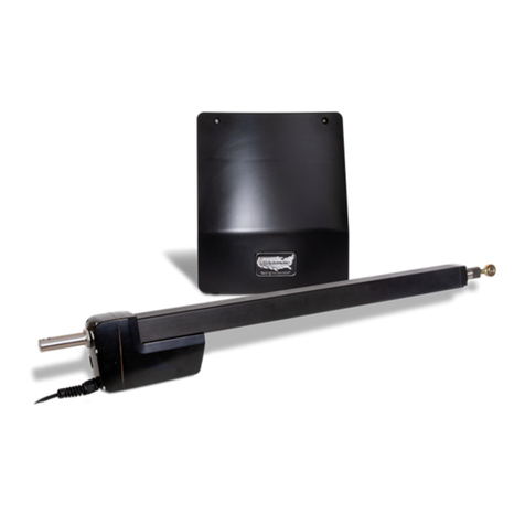
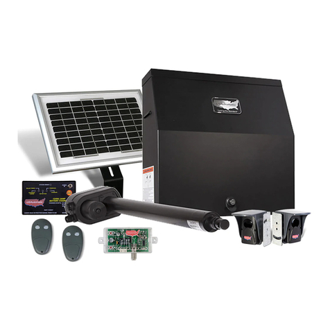
US Automatic SENTRY 300 S Operating instructions

Installation/Owners Manual
Battery Powered Solar or AC Charged
MADE IN THE USA
www.sentrygateopener.com
Designed to
open all types
of gates in all
kinds of places.
High Quality Low Voltage
Vehicular Swing Gate Opener
High Quality Low Voltage
Vehicular Swing Gate Opener
3
Year
Warranty
SENTRY®300 S / 300 D

1
INTRODUCTION
About the Sentry.......................................................................................................... 2
Safety Information ....................................................................................................... 3
Sentry Parts Inventory ................................................................................................. 5
Sentry Hardware Inventory.......................................................................................... 6
General Tool Requirements......................................................................................... 6
PREPARATION AND OVERVIEW
GateQualications/Applications.................................................................................. 7
ProperGateDesign..................................................................................................... 7
INSTALLATION
1. MountingSiteReview ............................................................................................ 8
2. DetermineProperBracketsandOpeningMethod................................................. 9
3. AttachingUniversalActuatorBrackettoHingePostorPostBeingUsed........... 11
4. AttachActuatorBrackettoUniversalActuatorBracket....................................... 12
5. InstallLinearActuatortoActuatorBracket.......................................................... 12
6. InstallGateBrackettoLinearActuator ................................................................ 13
7. InstallGateBrackettoGate................................................................................. 13
8. PrepareControlBoxforInstallation..................................................................... 13
9. InstallSentryControlBox .................................................................................... 14
SplicingforSentry300SLinearActuatorCable(ifneeded)
10.SentryPlugNGoHarness .................................................................................. 15
11.InstallBattery ...................................................................................................... 15
12.InstallChargingSystem(ACorSolar)................................................................. 16
13.ConnectChargeDevicetoChargeController ..................................................... 17
14.ChargeControllerOperationCheck .................................................................... 17
15.InstallLinearActuatorCable................................................................................ 18
16.SentryPlugNGoHarnessFinalInstallation ....................................................... 18
17.SensitivityAdjustmentsandEntrapmentAlarm ................................................... 19
19.AdjustingGate1andGate2Sensitivity .............................................................. 20
20.ExtendandRetractLimitAdjustments................................................................. 20
21.OperatingGatefortheFirstTime ........................................................................ 21
22.MakingFinalAdjustments.................................................................................... 22
23.InstallSafetySigns .............................................................................................. 22
24.ProgrammingTransmitterandReceiver .............................................................. 22
ENTRAPMENT ZONES...................................................................................................... 24
PERIODIC SERVICE........................................................................................................... 24
SENTRY 300 D GATE 2 INSTALLATION...................................................................... 25
ACCESSORIES .................................................................................................................... 28
TROUBLESHOOTING......................................................................................................... 34
APPENDIX ........................................................................................................................... 41
WARRANTY ......................................................................................................................... 45
TABLE OF CONTENTS

2
SENTRY®300 Series AUTOMATIC GATE OPENER
TheSentryGateOpenerisintendedtobeinstalled
onvehicularClassI,II,IIIorIVgatesasdenedby
UL325,(thestandardthatregulatesgateopener
safety,asestablishedandmadeeffectiveMarch14,
2003,byUnderwritersLaboratories,Inc.)
TheSentryGateOpeneristhersttrulysolar
chargedgateopenerfortheDoItYourself
market.Thesystemdesignandtheaccessories
recommendedareallSolarFriendlymeaningthat
theyrequiretheleastamountofenergypossible
toperformthejobtheyweredesignedtodo.The
solaroptionallowsyoutoinstallthegateopenerin
remoteareasorinapplicationswhereyoupreferto
besolarcharged.Solarchargingprovidesisolation
fromlightningthatmightdamagetheunitviathe
ACpowerneededforthetransformer.
The Sentry Gate Opener is powered by a 12 VDC battery(notincluded).Thisbatteryischarged
bythesuppliedtransformerwhichrequiresACpower(120VAC)tobeeitheratthegateareaorwithin
1000feetofthegatearea.IftheACpowerismorethan10feetfromthegateopenercontrolboxthen
additionalextensioncableisrequired(seeSentrychargecableextensionkitinformation).
Ifpreferred,youmayusetheoptionalSentrySolarPanelkit(PN520015)tochargethebattery.
Typicallyonlyonepanelwillberequired.TheSentryGateOpeneriscapableofahighnumberof
cyclesperday.Forinformationonwhatyoucanexpectfromasolarchargedsystemseethesolar
chargingsectionofthismanual.(page41)Accessoriesthatareaddedtoyourgateopenermustbe
solarfriendlyaccessoriesandtheywillbeidentiedassuch.
The Sentry Gate Opener features an easy to connect Plug N Go wiring harness that eliminates
the need for any complicated wiring.Theonlywiringrequiredconsistsoftwowiresfromthe
harnessthatmustbeconnectedtothebatterypositiveterminal(redwire)andbatterynegative
terminal(blackwire).Allcomponentshavebeenpre-installedsothatinstallationcantypicallybe
completedinlessthanonehour.
The Sentry control board features high quality components and industry leading ideas such
as auto resetting fuses for motor protection.Theoldautomotivetypefusethatfrequentlyfail
havebeendesignedoutofthiscontrollertoavoidtheunnecessaryexpenseofbuyingfuses.Another
patentpendingitemdesignedintothecontrolboardistheonboardpotentiometersforadjustingstop
limits.Manyotherfeatureshavebeendesignedintothecontrolboardtoensuresuperioroperation
foryearstocome.AttentiontodetailandqualitypartsmakestheSentryGateOpenertheFirstHigh
QualityGateOpenerfortheDoItYourselfInstaller.USAutomaticappreciatesthefactyouhave
recognizedthequalityoftheSentrygateopenerforyourinstallationandwouldappreciateyour
commentsonhowwearedoingsothatwemaycontinuetobuildanddesignproductsinthefuture
thatworkthewayyouwantthemto.
PLEASE READ THE ENTIRE MANUAL CAREFULLY PRIOR TO INSTALLATION.
Indoingso,alongwithperformingtheinstallationinstep-by-steporder,youwillachieveoptimal
results.YourSentrycontrolboardwasdesignedwithacurrentsensesafetyfeatureandwestrongly
recommendothersafetydevicessuchasphotoeyestomakeeachparticularinstallationassafeas
possibleandreducetheriskofpersonalinjuryand/orpropertydamage.
PleasereadcarefullyandunderstandtheSafetySectionofthemanual.

3
USAutomaticgateoperatorsarecertiedtoUL325VehicularClassI,II,IIIandIVswinggatestandards.
UL325identiesfourdifferentclassesofgateoperators.Theseclassesare:
Class I: Residentialvehiculargateoperator-vehiculargateoperator(orsystem)intendedforuseina
homeofonetofoursinglefamilydwellingsoragarageorparkingareaassociatedtherewith.
Class II:Commercial/Generalaccessvehiculargateoperator-vehiculargateoperator(orsystem)
intendedforuseinacommerciallocationorbuildingsuchasmulti-familyhousingunit(veor
moresinglefamilyunits),hotelgarages,retail,orotherbuildingsservicingthegeneralpublic.
Class III:Industrial/Limitedaccessvehiculargateoperator-vehiculargateoperator(orsystem)
intendedforuseinanindustriallocationorbuildingsuchasafactoryorloadingdockareaor
otherlocationsnotintendedtoservethegeneralpublic.
Class IV:RestrictedAccessvehiculargateoperator-vehiculargateoperator(orsystem)intended
foruseinaguardedindustriallocationorbuildingsuchasanairportsecurityareaorother
restrictedaccesslocationsnotservicingthegeneralpublic,inwhichunauthorizedaccessis
preventedviasupervisionbysecuritypersonnel.
INSTALLATION
Install the gate operator when:
• Operatorisappropriatefortheconstructionofthegateandusageclassiscorrectforthe
installation.
• Allexposedpinchpointsareeliminatedorguarded.
• Thegateisavehiclegate.Pedestriansmustbesuppliedwithaseparateaccessopening.
• Thegateisinstalledinalocationwhereenoughspaceissuppliedbetweenadjacentstructuresand
thegatethatwhenopeningorclosingthechanceofentrapmentisreduced.
• Thegatedoesnotswingintopublicaccessareas.
• Thegateisproperlyinstalledandswingsfreelyinbothdirections.Donotoveradjustthesensitivity
adjustmenttocompensateforanimpropergateinstallation.
• Allcontrolsarelocatedatleastsixfeetawayfromthegatetoeliminatethechanceoftheperson
operatingthegatefromcomingincontactwiththemovinggate.Donotinstallexternalbuttons,
whichcanbeusedtooperatethegatewithinthereachofchildren.
• Placardsareinstalled,oneoneachsideofthegateandvisibleinthegatearea.
• Allcontactsensorsusedforsecondaryentrapmentsafetydevicesandtheirwiringisinstalledina
mannerwhichprotectsthemfrommechanicaldamage.
• Allnon-Contactsensorsusedforsecondaryentrapmentsafetydevicesarelocatedsothatthe
signalfromthetransmittertothereceiverisnotinterferedwithbyadjacentstructures.Allexposed
wiringmustalsobeprotectedfrommechanicaldamage.
SECONDARY ENTRAPMENT DEVICES
USAutomatic designs all control boards with secondary entrapment inputs. USAutomatic
recommends that UL325 listed secondary safety devices be installed with all installations.
USAutomaticrecommendsthatthesedevicesbeconnectedafterpropergateinstallationand
operationhasbeenveried.Thenconnectonedeviceatatimetoverifyproperoperationbefore
installingthenextdevice.Ensurethatpowerisdisconnectedfromthecontrolboardpriortowiring
anyaccessory.
SAFETY INSTALLATION INFORMATION

4
WARNING
TO REDUCE THE RISK OF INJURY OR DEATH
1. READ AND FOLLOW ALL INSTRUCTIONS
2. Study the entire Safety Section paying particularly close attention to the entrapment zones
and be aware of these areas not only during use but also during any adjustments to the unit.
3. Do not attempt to enter the gate area while the gate is moving. Wait until the gate comes to
a complete stop.
4. Never let children operate or play with gate controls or any other activation device. Keep
remote control away from children.
5. DO NOT ALLOW CHILDREN TO PLAY IN THE AREA OF THE GATE.
6. Do not allow anyone to ride on the gate.
7. Always keep people and objects away from the gate.
8. NO ONE SHOULD CROSS THE PATH OF A MOVING GATE.
9. Operate the gate only when it is fully visible, free of persons or obstructions, and properly
adjusted.
10. Do not attempt to “beat the gate” while the gate is opening or closing. This is extremely
dangerous.
11. Test gate operator monthly. The gate must stop and reverse directions upon contacting a rigid
object or when the secondary entrapment device is activated.
12. After all adjustments have been made to the sensitivity (current sense) circuit, secondary
entrapment devices and all other external devices installed, the safety devices must be
checked again. Failure to adjust and retest the gate operator can increase the risk of injury
or death.
13. Verify that the emergency release (manual release) pin can be easily removed.
14. KEEP GATES PROPERLY MAINTAINED. Tighten all bolts and grease hinges and pivot points.
15. THE ENTRANCE IS TO BE USED BY VEHICLES ONLY. Pedestrians must use a separate
entrance.
16. All safety features required by UL 325 are incorporated in the capabilities of all USAutomatic
Control boards and should be utilized, including but not limited to, safety edges, photo
electric eyes, reverse sensing.
17. Test the current sense feature and all safety devices regularly to insure correct operation.
18. The USAutomatic battery charger is designed to operate with a recommended +12 VDC,
sealed maintenance free type Group U-1 battery. 30 amp hour minimum.
19. All control stations should be located at least 6 feet from any moving part of the gate
or operator.
20. Do not ever install any control device where a user will be tempted to reach through the gate
or fence to activate a gate.
21. Do not attempt to completely seal the control box. Battery needs some air ow.
22. SAVE THESE INSTRUCTIONS!!

5
Universal Actuator
Bracket
Part#610400
1 per
Square Post Flush
Mount Bracket
Part#610402
1 per
Round Post Flush
Mount Bracket
Part#610404
1 per
Actuator Bracket
Part#610406
1 per
Gate Bracket
Part#610105
1 per
Gate Support
Bracket
Part#610120
2 per
Bronze Bushing
Part#610530
2 per
Manual release pin
Part#610534
1 per
Manual release clip
Part#610535
1 per
Plug N Go Harness
Part#630040
1 per
1/2” Cable Gland
Part#620022
1 per
Entrapment
Siren
Part#530015
1 per (Installed)
Safety Sign
Part#601027
2 per
Transmitter
Part#030210
2 per
Transformer
Part#520008
1 per
Charge Controller
Part#520007
1 per (Installed)
LCR Receiver
Part#030200
1 per (Installed)
SENTRY 300 Series partnumber020320
PARTS INVENTORY
Linear Actuator
Part#510300
1 per
Instructional DVD
1 per
Control Board
Part#500415
1 per (Installed)
Charge Controller
LCR Receiver

6
Transmitter
Part#030210
2 per
Transformer
Part#520008
1 per
Charge Controller
Part#520007
1 per (Installed)
LCR Receiver
Part#030200
1 per (Installed)
Control Board
Part#500415
1 per (Installed)
Charge Controller
LCR Receiver
3/8 x 16 nylon lock nut
Part#610518
5 per
1/4 x 20 nylon lock nut
Part#610526
2 per
3/8 USS at washer
Part#610514
6 per
3/8 SAE at washer
Part#610516
2 per
1/4 SAE at washer
Part#610524
4 per
Nylon washer
Part#610528
2 per
3/8 x 2 1/2” shoulder bolt
Part#610512
3 per
3/8 x 16 x 8” carriage bolt
Part#610510
2 per
Tap bolt
1/4 x 20 x 3 1/2”
Part#610522
2 per
Tap bolt
1/4 x 20 x 2 1/2”
Part#610520
2 per
#12 x 1 1/4 self tap hex screw
Part # 610532
4 per
GENERAL TOOL REQUIREMENTS
Tools required for most installations:
•Wrenches–7/16,9/16and10mm •Sockets7/16,3/8and5/16
•Drill •Drillbits1/4and3/8inch
•Drilladapterforsocketattachment •Pliers
•Hacksaw •Levelandtapemeasure
Weldingistherecommendedmethodofsecuringthelinearactuatormountstothegateandhingepost.
Boltonbracketsareprovidedandareacceptablebutmayrequirefrequentservicetokeeptight.They
mustbeverysecurelyattached(i.e.carriageboltswithlocknutsandwashers).Lagtypeboltsarenot
recommended.Looseorunstablelinearactuatormountswillresultinimproperoperation.
IMPORTANT CAUTIONS:
1. Donotperformanyweldingwiththeactuatorcablepluggedintothecontrolboardorthebattery
connected.Seriousdamagetothecontrolboardand/orbatterymayoccurifattempted.
2. Usecontrolboxasatemplatetodeterminemountingscrewlocationsandthenattachscrews
andslideoncontrolbox.Donotattempttoholdcontrolboxanddrillmountingholes.Thiscould
damagethepreinstalledcomponents.
3. AlwaysdisconnectthebatterypowerfromthecontrolboardusingthePlugNGoharnesspriorto
wiringanydevicestothecontrolboard.
HARDWARE INVENTORY

7
GATE QUALIFICATIONS/APPLICATIONS
TheSentrygateopenerisdesignedandratedforvehicularclassI,II,IIIorIVswinggatesupto20
feetinlength.Maximumgateloadnottoexceed400poundsand20feetinlength.
TheSentryGateOpenerisrecommendedforGatesthatmeetthefollowingdescriptions:
TheSentrygateopenerisdesignedandsuppliedwithuniversalmountingbracketstotmosttypes
ofgateinstallations.Hingepostfrom23/8”to6”roundorsquarecanbeusedwiththeincluded
universalmountinghardware.
Chain Link Gate
16feetmaxlength
Maxweight350lbs.
Farm Gate
20feetmaxlength
Maxweight300lbs.
Ornamental Iron
12feetmaxlength
Maxweight400lbs.
PROPER GATE DESIGN
IMPORTANT- A GATE OPENER CANNOT OVERCOME A POORLY DESIGNED GATE.
Since the gate is a major component of the system, great care and concern must be given to
the gate design. USAutomatic,LTDisnotresponsibleforanydamagetoagateinwhichthegate
openerisinstalled.Apoorlyinstalledormisadjustedgatecouldbedamaged.Itistheresponsibility
oftheinstallertoverifypropergateinstallationpriortoopenerinstallation. Asageneralrule,agate,
whichistobeautomaticallyoperated,mustbestrongerandsmootherthanoneoperatedmanually.
• Doesthegateswingsmoothlywithoutbindsorexcessiveresistance?
• Swinggatesshouldswinglevelandplumbtopreventtheopenerfromhaving
toliftthegateopenorclosed.
• Swinggatesshouldnotrequireawheeltosupportthem.Wheelscreatedrag,
whichwillcauseopenerproblems.Awheelisgenerallyasignofaweakhinge
systemoraweakgateframe.
• Isthegateframeofsubstantialstrengthwithoutexcessiveweight?
• Willtheframewithstandnormalwindloadconditionswithoutswayorvibration?
• Willthegateclosecorrectlywithoutbeinghand-guidedorliftedtoclose?
• Arethehingessuitedforanautomaticgateopener?Werecommendbearing
typehingestoreducefrictiondrag.
• Willareinforcementbraceberequiredtoattachthelinearactuatortothegate
ordoesasuitablecrossmemberexistinthegatedesign?
If any of these problems exist, they must be corrected to achieve a reliable automatic gate system.

8
Sentryinstalledandshownintheextendedposition.
Actuatormustbeinstalledlevelandattachedtoahorizontalcrossmemberasshown.
Mounting Site Review
Review the following items prior to installation and predetermine the solution to any
problems which may exist:
• Doessufcientspaceexistformountingandfutureservicingoftheopenerandcontrolbox?
• Whichdirectionwillthegateswing?
• Willthegateopenerpullthegateopentotheinside(PulltoOpen)?
• Willthegateopenerpushthegateopentotheoutside(PushtoOpen)?
• Wherewilltheuniversalactuatorbracketandgatebracketbesecuredatthehingepostand
tothegate?
• Wherewillthecontrolboxbemountedtosupporttheweightofthebatteryandcanitbe
locatedwithin8feettopreventsplicingoftheactuatorcable?
• Howwillyouchargethebattery?WillitbeACorSolarcharged?
• Howfarawayisthe110VACreceptaclesforthetransformer?Transformerissupplied
with12feetofcable,ifextensionisneededuseSentryChargeCableExtensionKit(part
#630050).SeeAppendixB(pg42)forextensioncablekitinformationandrecommended
wiresizechartforextensiondistanceneeded.
• Ifsolarcharged,wherewillthesolarpanelbelocatedsothatoptimumsunlightisreceived?
Solarpanelinmostcasesneedstofaceasouthwestdirection.Solarpanelcomeswith15’
ofcable.Ifmoreisneeded,useSentryChargeCableExtensionKit(part#630050).
• Howwillaccessorycontrolwiring,ifany,bebroughttothecontrolbox?Knockoutsare
providedincontrolboxbottomforconduit.
• Haveallsafetyconcernsbeenaddressed?(SeeSafetySectionpg.3-4)
Gate Bracket Universal
Actuator
Bracket
Linear Actuator
Installed Level
Horizontal Gate
Section
1
INSTALLATION

9
Determine Proper Brackets and Opening Method
Mounting Brackets
Determining which of the brackets will be needed for your installation.
TheSentrygateopenerissuppliedwithuniversalbracketstomountonround
orsquarehingepostranginginsizefrom23/8”to6”.Somepiecesmaynotbe
needed for your installation.
Thehingepostisthepostyourgatehingesareattachedto.Followthe
stepsbelowtoidentifywhichoftheincludedbracketswillbeneededforyour
installation.
Is the hinge post round or square?
Squarepostwillusethe“squarepostushmountbracket”
Roundpostwillusethe“roundpostushmountbracket”
NOTE:Ifaroundpostistobeuseditmightbenecessarytobracethepostso
thatitdoesnotrotate.Aroundpostsimplyinstalledinconcretewillrotate,if
possibledrillholesthroughthepostandinsertrebarthroughthepostpriorto
concretetopreventrotation.
Is the gate a light weight farm gate?
Ifso,usethe“gatesupportbrackets”toattachthegatebracketsothatthe
boltscanbesecurelytightened.
Universal Actuator Bracket
Theuniversalactuatorbracketcanbeinstalledinmanydifferentwaysto
accommodateyourgateopenerinstallation.Usetheimagesbelowtohelp
understandthemountingoptionsforthisbracketanddeterminetheinstallation
methodyouaregoingtouse.Theimagesareforreferenceonlyandyourinstallationmightdiffer.
Universalactuatorbracketmustbesecurelyinstalled.Drillingthroughthepostisthestrongest
method.Itisalsorecommendedthatthesquarepostushmountbracketortheroundpostush
mountbracketbeinstalledforstrengthonoppositesideofpostfromtheuniversalbracket(see
guresbelow).
Whendeterminingwheretheuniversalactuatorbracketwillmountonthehingepostyoumustalso
considerwherethegatebracketisgoingtoconnecttothegate.Thegatebracketisgoingtoattach
approximately34”outonthegatemeasuredfromthegatehingecenter.
Onceuniversalactuatorbracketlocationisdetermined,verifythatthegatebracketcanbeinstalledto
thegatesothatlinearactuatorislevel.
Square
Post
Bracket
Round
Post
Bracket
Universal
Actuator
Bracket
Gate
Support
Bracket
2

10
Pull to Open Installation
Thisinstallationmethodisthemostcommonwherethegateswingsintotheproperty/driveway.
Nomatterwhichwayyoudecidetoinstalltheactuatorbracketanduniversalactuatorbracketthe
pivotpointbelowmustbelocatedinapproximatelythispositionforapulltoopeninstallation.
Push to Open Installation
Thisinstallationmethodiscommon
wherethedrivewayslopesupentering
thepropertyandgatemustswing
outtoavoidinterference.Thistypeof
installationplacestheactuatorbracket
andlinearactuatorintothedrivearea
slightly.Anotherinstallationmethod
wouldbetoinstallasaPulltoOpen
andplacelinearactuatoronoutside
ofproperty.
Pushtoopeninstallationcanbe
achievedbyinstallinguniversalactuator
bracketandactuatorbracketasshownin
gurebelow.Dimensionsforthisinstall
methodare7”and4”fromhingecenter.
Universalactuatorbracketholepatternallowsfortheactuatorbrackettobeinstalledasshowninthis
locationonly.Establishenoughoffsetintherearactuatorpivotpointtoallowthegatetoclosefrom
theopenposition.
IMPORTANT: If Installation is Push to Open, control switch #2 “operating direction reverse”
must be turned “ON”.
NOTE: Pull to Open & Push to Open Dimensions are measured from the gate hinge center
(pivot point).
GateHingeCenter
(pivot point)

11
Attach Universal Actuator Bracket to hinge post or post being used
Mounting hardware needed:
• two3/8”x16x8”carriagebolts
• two3/8”USSatwashers
• two3/8”nylonlocknuts
Theuniversalactuatorbracketcanbeinstalledinmanydifferentways
toaccommodateyourgateopenerinstallation.Thepicturesherearefor
referenceandyourinstallationmightdiffer.
Universalactuatorbracketmustbesecurelyinstalled.Drillingthroughthe
postisthestrongestmethod.
NOTE: In all cases, the universal actuator bracket should be aligned
level with a horizontal gate section.
1. AttachUniversalActuatorBracketwithassociatedbracket(roundor
squarepostmount)aspreviouslydeterminedtoworkbestwithyour
openingmethod.Itisrecommendedthatthesquarepostushmount
bracketortheroundpostushmountbracketbeinstalledforstrength
onoppositesideofpostfromtheuniversalbracket.
2. Installwithcarriagebolts,locknutsandwashers.
3. Tightennutssecurely.
Weldingistherecommendedmethodofsecuringthelinearactuatormountstothegateandhinge
post.Boltonbracketsareprovidedandareacceptablebutmayrequirefrequentservicetokeep
tight.Theymustbeverysecurelyattached(i.e.carriageboltswithlocknutsandwashers).Lag
typeboltsarenotrecommended.Looseorunstablelinearactuatormountswillresultinimproper
operation.
3
IMPORTANT CAUTIONS:
1. Donotperformanyweldingwiththeactuatorcablepluggedintothecontrolboardorthebattery
connected.Seriousdamagetothecontrolboardand/orbatterymayoccurifattempted.
2. Usecontrolboxasatemplatetodeterminemountingscrewlocationsandthenattachscrews
andslideoncontrolbox.Donotattempttoholdcontrolboxanddrillmountingholes.Thiscould
damagethepreinstalledcomponents.
3. AlwaysdisconnectthebatterypowerfromthecontrolboardusingthePlugNGoharnesspriorto
wiringanydevicestothecontrolboard.

12
Attach Actuator Bracket to Universal Actuator Bracket
Theactuatorbrackethasa3/8”predrilledholethatthelinearactuatorwill
mountto.Thisisthepivotpointforthelinearactuator.Inallcases,the
universalactuatorbracketshouldbealignedlevelwithahorizontalgate
section.(seeMountingSiteReview)
For a Pull to Open installation - thepre-drilledholemustbelocated5”
behindthegatehingeand8”totheinsideoftheproperty.
For a Push to Open installation - thepre-drilledholemustbelocated7”in
frontofthegatehingeand4”tothedrivesideofthehinge.
Thesedimensionsaremeasuredfromthecenterofthegatehinge(pivotpoint).
Hardware needed:
• two3/8”x21/2”shoulderbolts
• two3/8”USSatwashers
• two3/8nylonlocknuts.
1. Attachactuatorbrackettouniversalactuatorbracket.
2. Verifythatactuatorbracketpivotholedimensionislocatedinthe
correctpositionseepage10fordimensions.
3. Tightenboltssecurely.
Install Linear Actuator to Actuator Bracket
Theactuatorcanbemountedintwodifferentpositionsasshown.Installingthe
actuatoronitssidecanallowforhidingitbehindacrossmemberinthegateframe.Thegatesbelow
areshownintheclosedposition.
1. Installnylonwashersandbronzebushingsintorearoflinearactuator.
2. Installthelinearactuatorintoactuatorbracket
3. Securethelinearactuatorinplaceusing3/8x21/2”shoulderboltand
two3/8SAEwashers.
4. Use3/8nylonlocknuttosecure,tightenrmly.
Actuator should swing freely, DO NOT OVER TIGHTEN!
CAUTION:Ifmountingactuatoronitsside,ensureactuatorcasedoes
notcomeincontactwithanyobjects.Mountasshownsothatwidepart
ofmotorcaseandcableisawayfromgate.
4
5
Actuator
Bracket
Pivot
Point
Predrilled
Hole

13
Install Gate Bracket to Linear Actuator
Installmanualreleasepin,gatebracketandmanual
releasecliptolinearactuatorextensionrodend.
Install Gate Bracket to Gate (Pull to Open Only)
To determine where the gate bracket will be installed follow these steps: The linear actuator
should be connected to the actuator bracket at this point. NOTE - The linear actuator was shipped
from the factory set to the fully retracted position.
1. Swinggatetothefullyopenposition.
2. Nowopengateanothercoupleofinches(thegatewillneveropen
morethanthisposition).Thegatecanbeadjustedlatertoopena
little less if needed.
3. Swinglinearactuatoraround(shouldswingfreely)inalevelposition
tomeetthefullyopengate.Thisiswhereyoushouldinstallthegate
bracketonthegate.
4. Markthelocationofthe1/4”holesforthemountingbracket.(see gure)
5. Removepinandclipfrombracket.
6. Attachbrackettogate(ifusingalightweighttubularfarmgateusegate
supportbracketforsupport).Usethe1/4”x21/2”or31/4”tapbolts
dependingongatethickness,four1/4”atwashersandtwo1/4”nylon
locknuts.Tightensecurely.
7. Attachactuatortothenowsecuredgatebracketusingmanualreleasepin
andclip.
8. Thegateshouldnowbefullyopenedwiththeactuatorattached.
9. Verifythatlinearactuatorislevelandallpieceshavebeen
installedcorrectly.
Installing Gate Bracket to Gate for Push to Open configuration
ProcedureisidenticaltothestepsforPulltoOpenexceptthegatewillbeinthefullyclosedposition.
Forapushtoopenconguration,youwillneedtoreversetheoperatingdirectionforthegateonthe
controlboard.
Preparing Sentry Control Box
for Installation
Thecontrolboxhastwoholesinthebottomofthebox
providingaccesstothewirecompartment.Thelargehole
isfortheactuatorcableandthesmallerholeisforthe
chargedevicecable.
Installtheprovidedcableglandintothesmall
hole as shown here.
Cable
Gland
6
7
8

14
Install Sentry Control Box
Thecontrolboxshouldbeinstalledinalocationthatwillnotrequire
theeightfootlinearactuatorcabletobespliced.Ifthecablemustbe
spliced,refertothesplicinginstructionsbelow.Themostcommon
locationwouldbeonafenceorwalladjacenttoyourgate.Avoid
placingthecontrolboxbehindsolidmetalobjectsthatmightinterfere
withthereceiverreception.Theantennaforthereceiverislocated
insidethecontrolboxandthiscouldreducetheoperatingrange.
1. Usecontrolboxasatemplatetodetermineandmarkthe
mountingscrewlocationsusingthe4mountingholesshownin
gurehere.
2. DrillmountingholesforscrewsDONOTATTEMPTTO
HOLDTHECONTROLBOXINPLACEWHILEYOU
DRILLTHEMOUNTINGHOLES.Thiscoulddamage
thepreinstalledcomponents.
3. Attachthe4#12hexheadselftappingmetalscrews.
4. Mountthecontrolboxonthescrews.
Verify the structure the control box is mounted on is sufcient enough
to hold the control box and battery securely.
Splicing for Sentry 300 S Linear Actuator Cable (if needed)
TheSentrylinearactuatorcomeswith8feetofcable.Avoidsplicing
thiscableifpossible.Ifthecontrolboxmustbelocatedinsucha
waythatsplicingisrequiredfollowtheguidelinesbelowtoavoid
problems.Determinethelengthofadditionallinearactuatorcable
neededandeitherbuildityourselforvisitwww.sentrygateopener.
comfororderingthelengthofextensioncableneeded.
1. Locatethelinearactuator8pinconnector.Measure18”from
connectorandmark.
2. Cutcableatthe18”mark.Thiswillallowenoughcabletobesplicedandplacedinthewire
compartment.
3. Bringextensioncableintocontrolboxandsplice5wiresusingwirenuts.
4. Useapprovedweathertightelectricaljunctionboxforthesplicelocatedoutsidethecontrolbox.
5. Conduitshouldbeusedbetweenjunctionboxandcontrolbox.Controlboxknockoutisfor
1/2”conduit.
6. Theextensioncablemustconsistof5wires,2fourteengaugewiresand3eighteengaugewires.
•Redwirewithwhitestripe–14gauge(distanceaddedisgreaterthan50feetuse12gauge)
•Blackwirewithwhitestripe–14gauge(distanceaddedisgreaterthan50feetuse12gauge)
•Orangewire–18gauge(distanceaddedisgreaterthan50feetuse16gauge)
•Greenwire–18gauge(distanceaddedisgreaterthan50feetuse16gauge)
•Whitewire–18gauge(distanceaddedisgreaterthan50feetuse16gauge)
7. Withextensioncablenowinthejunctionboxstripandpreparetosplicetolinearactuatorcable.
8. Routelinearactuatorcableintojunctionboxandspliceusingwirenuts.
NOTE: Cable splice must be water tight to keep moisture away from splices and prevent problems
Mounting Holes 4 Places
9
14.25”
17.7”
11.7”
14.5”

15
Sentry Plug N Go Harness
ThePlugNGoHarnesscomespreinstalledandshouldbeplugged
intothebottomofthechargecontroller.Plugiscolorcoded.Red
connectstopositivebatterypostandBlackconnectstonegative
batterypost.Onceconnected,placeharnessintowirecompartmentto
prepareforbatteryinstallation.
Install Battery
BATTERY REQUIRED FOR OPERATION (Battery not included)
Recommendedbatterytype-12-volt,GroupU-1;sealed
(maintenancefree);30amphourminimum.Thisbatteryis
sometimesdescribedasanon-spillablelawntractorbattery.Battery
physicalsizemustnotexceed9”wide,7”talland53/4”deep.
ThePlugNGoharnesshastwo1/4”ringterminalstoconnectto
bolttypebatterypost.
CAUTION-Donotinstallwetcellbatteryintocontrolbox;thistype
ofbatteryusuallyhasremovablecapsusedforserviceandwillvent
corrosivefumesintocontrolbox.
1.Installthebatteryintothebatterycompartment.
2.ConnectOringterminalsfromharnesstothebattery.
NOTE: Redwiretopositivepostofbattery
Blackwiretonegativepostofbattery
3.Tightentheboltssecurely(boltsshouldbesuppliedwiththebattery).
10
11
1/4” Ring terminal for battery
Red connects to positive battery post
Black connects to negative battery post
Charge controller connector
15 amp fuse
Gate 1 and Gate 2 linear
actuator power plugs

16
Install Charging System - AC or Solar
For AC Charge Option - Install Transformer
Supplied with opener
TheUSAutomatictransformer(PN520008)suppliedisalowvoltage
ULapprovedtransformerforthistypeofapplication.Thetransformeris
equippedwithaDCplugforeasyconnectiontothechargecontrollerand
caneasilyprovide575cyclesofoperationadaywithoutdecreasingthe
batterycharge.IntheeventACpowergoesouttheopenerwilloperate
forweeksonthebattery(ifcyclesperdayarebelow20)beforeneeding
service.Accessoriesconnectedtotheopenerarecritical.AlwaysuseSolar
Friendlyaccessoriestohelpavoidprematurebatteryfailureincasesof
poweroutages.TRANSFORMER MUST NOT GET WET.
1. Loosencableglandnutandroutethecablefromthechargedeviceinto
thecontrolbox(seegure).EnsurethatDCplugcanreachthecharge
controller“PowerIn”connector.
2. Tightencableglandnuttoholdcableinplace.
3. Connectthetransformertoanapprovedelectricalreceptacle.
NOTE: The 110 VAC receptacles should be installed by a qualied
electrician, per local building codes.
Ifreplacementbecomesnecessaryvisitwww.sentrygateopener.comtoorder,partnumber520008.
Failuretousethepropertransformercandamagethechargecontroller.
For Solar Charge Option - Install the Solar Panel
Optional Solar Panel Kit Part Number 520015 - not included
Thelocationofthesolarpaneliscriticalforproperbatterycharging.ThepanelneedstofaceaSouth
toSouthwestdirectionandbeinstalledattheangleofthesuppliedsolarpanelbracket.Forproper
operationthepanelmusthaveunobstructedsun.TheSolarPanelneedstobemountedsothatit
receivesfullsunlight.EvenasmallamountofshadeorblockagewillcausetheSolarPaneltocease
charging.SomethingastinyasangertipshadowwillaffecttheSolarPanel.
Optimizing Solar Panel Location
Thechargecontrollersensesthechargemethodinstalled(ACorSolar)
andchargesthebatteryattheoptimumchargerate.Thesolarpanel
outputsvoltageandcurrenttochargethebattery.Thisoutputvoltage
willvaryslightlyasthesunpassesoverthroughouttheday.Thecharge
controllercanbeusedtooptimizethisoutputvoltage.
• Tousethisfeatureidentifytimeofdayforthemaximumsolar
radiation(typicallyaround2pm).
• Facethepaneltowardthesunandobservethe“ExternalPower”
lightonthechargecontroller,adjustthepaneluntillightcomeson
andsecureinthatposition.
NOTE:Dependingonthetimeofyearandyourexactlocationtheoutputvoltagerequiredto
illuminate“ExternalPower”lightmaynotbepossible.Thisdoesnotindicateaproblem.Inthiscase
setpaneltofaceaSouthwestpositionandverify“SolarPower”lightison.Batteryisbeingcharged.
For additional information regarding Solar Charging, see Appendix A of this manual.
12
Cable Gland

17
Connect Charge Device to Charge Controller
(TransformerorSolarPanelKit)
TheSentrygateopenerchargecontrolleracceptsinputsfrom
eitherthesuppliedACtransformerortheoptionalsolarpanel.
ThetransformerandsolarpanelcomewithaDCplugforeasy
installation.Oncethechargedeviceisselectedandinstalled
connecttheDCplugintothechargecontroller“PowerIn”located
intheupperrightcornerofthechargecontroller.
If charge device cable needs to be extended to reach the
charge controller see appendix B of this manual.
Charge Controller Operation Check
Oncethechargedeviceispluggedintothechargecontrollerverifythefollowing:
Transformer:
1. Chargelightashesfor3secondsandgoesoff
2. Externalpoweranddetectionlightscomeon
3. Detectionlightstaysonfor3seconds,thencharginglightcomeson
Solar Panel:
1. Chargelightashesfor3secondsandgoesoff
2. Solarpoweranddetectionlightscomeon
3. Detectionlightstaysonfor3seconds,thencharginglightcomeson
IfExternalPowerorSolarPowerLEDisonandtheDetectionLEDison,thebatteryisnotconnected
tothecharger.VerifyRed/Blackconnectorsarepluggedintothebottomofthechargerasshown
above.
NOTE: Most batteries will not be completely charged when rst connected and the charging
light should come on when charge controller is rst connected. The fully charged light will
come on once battery is fully charged.
Whenusingasolarpanel,thechargecontrollerisdesignedtoonlychargethebatterywhenthere
isenoughsuntodoso.Ifthereisnosun,thelightsonthechargecontrollershouldbe“OFF”.This
featurereducesthedrainonthebatteryinsolarinstallations.Iftransformerisinstalledlightsare
operationalallthetime.
Charge Device
plugs in here
13
14

18
Install Linear Actuator Cable
Withthecontrolboxinstalledroutethelinearactuatorcableintothebottomofthecontrolboxusing
the11/4”holeintherearbottom.Slidetheholeplugthatisinstalledonthelinearactuatorcableinto
thecontrolboxholeandsnapinplace.
Ifcablelengthisexcessive,coilupandplaceinthewirecompartmentofcontrolbox.
EnsurethelengthallowsforconnectiontotheSentrycontrolboardGate1connector.
Sentry Plug N Go Harness Final Installation
At this point verify the following items have been completed:
3 Linearactuatorinstallationiscomplete.
3 Controlboxissecurelyinstalled.
3 PlugNGoharnessisconnectedtothechargecontroller.
3 PlugNGoharnessisconnectedtothebattery.
3 Batteryisinstalledinthebatterycompartmentofcontrolbox.
3 Chargedevicecableisroutedintocontrolboxandconnectedtothechargecontroller.
3 Linearactuatorcableisroutedintocontrolbox.
Verify the above items have been completed correctly before continuing. If necessary, correct
before proceeding. If completed, procede with the following steps:
1. Locatethepowerconnectorattachedtothelinearactuatorcable(redandblackwires).
2. ConnectittooneofthePlugNGoharnesslinearactuatorpowerplugs.Theseconnectorsare
designedsothatincorrectconnectionisnotpossibleanditdoesnotmatterwhichconnectoris
used.
3. Locatethelinearactuatorcable8pinplug.
4. ConnectittotheGate1connectorlocatedontheSentryControlboard.
5. Securelysnapinplace.
6. Onceallconnectionsaremadeplacewiresinwirecompartment.
NOTE: In case of an emergency,theGate1orGate2connectorcanberemovedatanytimefrom
controlboardtostopgatefrommoving.
This completes all cable connections and cable routing into
the control box.
15
16

19
Sentry Control Board Information
TheSentrycontrolboardiscapableofoperatingtwogates.Ifyourinstallationisasinglegateyoucan
operatethegateontheGate1orGate2connector.Setcontrolswitch“ON”fortheconnectorbeing
used.TheSentrygateopenerwasshippedwiththereceiverandentrapmentsirenalreadyconnected
tothecontrolboard;theseconnectionsareplugsthatcaneasilybedisconnected.
Sensitivity Adjustments and Entrapment Alarm
Gate1andGate2sensitivityadjustmentsarelocatedontheleftedge
ofthecontrolboard.
Sensitivityistheprimarysafetycontroldesignedintothecontrolboard.
Theadjustmentdialscontroltheamountofforcethegatecanapply
toanobjectbeforethegatewillstopandreversedirection.Ifthegate
sensesanobstructionitwillreversedirection.Ifitsensesasecond
obstructionbeforereachingthefullyopenorclosedpositionthegate
willshutdown.Theentrapmentalarmwhichispreinstalledinthe
controlboxwillsound.
Entrapmentalarmwillcontinue
for 5 minutes then shut off. The
entrapmentalarmcanberesetby
pressingthe“Reset”buttononthe
controlboard.
Iftwoobstructionsweredetected
andcontrolboardhasshutdown,
the“Reset”buttonwillhavetobe
pressedtore-activatetheopener.
17
Sensitivity Adjustments
Sentry Control Board
Reset Button
This manual suits for next models
1
Table of contents
Other US Automatic Gate Opener manuals

US Automatic
US Automatic PATRIOT RSL Operating instructions

US Automatic
US Automatic PATRIOT RSL Operating instructions

US Automatic
US Automatic PATRIOT I Operating instructions

US Automatic
US Automatic PATRIOT Series Operating instructions

US Automatic
US Automatic PATRIOT I Installation instructions

US Automatic
US Automatic Ranger HD Operating instructions

US Automatic
US Automatic STAR I User manual

US Automatic
US Automatic PATRIOT Series Operating instructions

US Automatic
US Automatic Ranger 500 S Operating instructions

US Automatic
US Automatic PATRIOT RSL User manual