Portwell PCS-8279 User manual

PCS-8279
In-Vehicle
Computing
User's
Manual
Document Name
PCS-8279 User Manual
Document No.
UM021341001
Version
1.0
Date
Feb. 2013
Reversion History :
Reversion
Date
Notes
Author(s)
From
To
1.0
1.0
Feb. 2013
Initial document issued
APT Editors

PORTWELL®
Technology
Copyright
© 2013 by PORTWELL® Technology Corp. All Rights Reserved.
No part of this publication may be reproduced, transcribed, stored in a retrieval
sys- tem, translated into any language, or transmitted in any form or by any
means such as electronic, mechanical, magnetic, optical, chemical, photocopy,
manual, or otherwise, without prior written permission from PORTWELL®
Technology Corp.
Other brands and product names used herein are for identification purposes
only and may be trademarks of their respective owners.
Disclaimer
PORTWELL® Technology Corp. shall not be liable for any incidental or
consequential damages resulting from the performance or use of this product.
PORTWELL® Technology Corp. makes no representation or warranty
regarding the content of this manual. Information in this manual had been
carefully checked for accuracy; however, no guarantee is given as to the
correctness of the contents. For continuing product improvement,
PORTWELL® Technology Corp. reserves the right to revise the manual or
make changes to the specifications of this product at any time without notice
and obligation to any person or entity regarding such change. The information
contained in this manual is provided for general use by customers.
This device complies to Part 15 of the FCC Rules. Operation is subject to the
following two conditions:
1. This device may not cause harmful interference.
2. This device must withstand any background interference including those
that may cause undesired operation.

Safety Information
Read the following precautions before setting up a PORTWELL Product.
Electrical
safety
•To prevent electrical shock hazard, disconnect the power cable from the electrical
outlet before relocating the system.
•When adding or removing devices to or from the system, ensure that the power
cables for the devices are unplugged before the signal cables are connected.
If possible, disconnect all power cables from the existing system before you add a
device.
•Before connecting or removing signal cables from the motherboard, ensure that all
power cables are unplugged.
• Seek professional assistance before using an adapter or extension cord.
These devices could interrupt the grounding circuit.
• Make sure that your power supply is set to the correct voltage in your area.
If you are not sure about the voltage of the electrical outlet you are using, contact
your local power company.
•If the power supply is broken, do not try to fix it by yourself. Contact a qualified
service technician or your retailer.
Operation safety
•Before installing the motherboard and adding devices on it, carefully read all the
manuals that came with the package.
•Before using the product, make sure all cables are correctly connected and the
power cables are not damaged. If you detect any damage, contact your dealer
immediately.
•To avoid short circuits, keep paper clips, screws, and staples away from connectors,
slots, sockets and circuitry.
•Avoid dust, humidity, and temperature extremes. Do not place the product in any
area where it may become wet.
• Place the product on a stable surface.
•If you encounter technical problems with the product, contact a qualified service
technician or your retailer.
CA
UTION
Incorrectly replacing the battery maydamage this computer. Replace only with
the same or its equivalent as recommended by PORTWELL® Technology
Corp. Dispose used battery according to the manufacturer's instructions.

TABLE
OF
CONTENTS
1 Function Introduction
1.1 Model Specifications.......................................................................................6
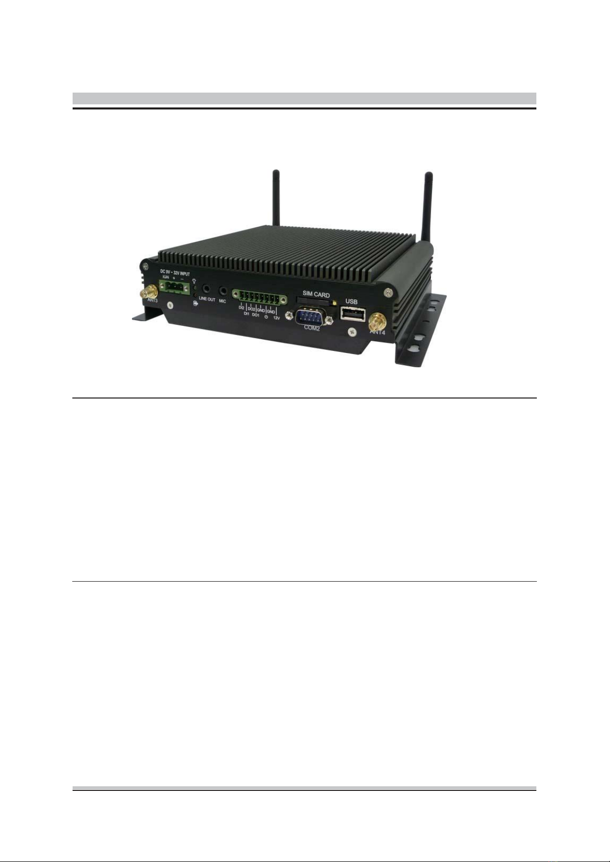
1.2 PCS-8279 Illustration <Mainboard, System>...............................................8
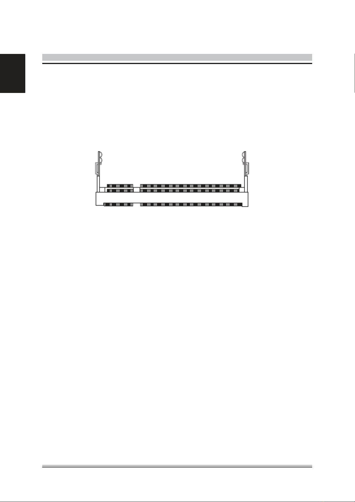
1.3 Memory Module Installation .........................................................................10
1.4 Architecture ..................................................................................................11
1.5 Principal Component Specification ..............................................................12
1.6 Internal Connector Specification..................................................................13
■ VGA Connector...........................................................................................13
■ USB Connector ...........................................................................................14
■ GPIO Connector .........................................................................................16
■ UART and GPIO Connector........................................................................17
■ LED Connector ...........................................................................................18
■ COM Connector ..........................................................................................19
■Audio Connector .........................................................................................23
■ SATA Connector..........................................................................................24
■ Mini PCI-E Connector .................................................................................26
■ Power Input Connector ...............................................................................28
■ SATA Power Connector...............................................................................29
1.7 External Connector Specification.................................................................31
■ USB Connector ...........................................................................................31
■ LAN Connector ...........................................................................................32
■ DVI-I Connector ..........................................................................................34
■ COM Connector ..........................................................................................35
1.8 Ignition Power Management Quick Guide....................................................36
2 System Installations
2.1 System Introduction .....................................................................................38
2.2 Opening Chassis..........................................................................................39
2.3 Installing Memory.........................................................................................40
2.4 Installing HDD / SSD....................................................................................41
2.5 Installing MINI PCI Express Expansion Card...............................................42
2.6 Installing MINI PCI Express Expansion Card...............................................43
2.8 Installing SIM Card.......................................................................................44
2.9 Installing Battery Module..............................................................................45

3 BIOS
3.1 Entering The BIOS .........................................................................................46
3.2 Main................................................................................................................48
3.3 Advanced .......................................................................................................49
3.4 Boot................................................................................................................55
3.5 Security ..........................................................................................................56
3.6 Chipset...........................................................................................................57
3.7 Exit .................................................................................................................59
4 Packing List
4.1 Packing List..................................................................................................60
5

1
F
unction
Introduction
1.1 Model
Specifications
CPU • Intel Cedarview Atom D2550 Dual Core 1.8GHz Processor
Chipset • Intel NM10
Memory • 1 x DDR3 1066MHz SO-DIMM up to 4GB
Graphics • Intel GMA3650
ATA • 2 x Serial ATA 2.0 Ports
LAN Chipset • 2 x Realtek 8111E Gigabit Ethernet
Watchdog • 1 ~ 255 level reset
Serial Port • Support 2 x RS-232 (COM1 with RS-232/422/485)
USB Port • 3 x USB 2.0 ports
LAN • 2 x RJ45 ports for GbE
Video Port • 1 x DVI-I Female Connector for DVI-D and VGAOutput
GPIO Port • Support 2 in and 2 out with Relay 12V / 100mA
Audio • Mic-in/Line-out
Expansion Bus • 3 x Mini-Card Slots
6

Antenna • 4 x SMA-type ExternalAntenna Connectors for WLAN / UMTS / GSM /
GPRS / GPS / Bluetooth
Storage • 1 x 2.5" drive bay for SATAType Hard Disk Drive / SSD
• 1 x SATA DOM
Qualification • CE, FCC Class A, eMark Compliance
Power Input • 9V - 32V DC Power Input
Power Management • Vehicle Power Ignition for Variety Vehicle
Power Off Control • Power off Delay Time Setting by Software, Default is 5 Mins
Backup Battery • Internal Battery Kit for 10 Mins Operating (Optional)
Operating Temp. • -40 ~ 70°C (SSD), ambient w/ air
Storage Temp. • -40 ~ 80°C
Relative Humidity • 10 ~ 90% (non-condensing)
Vibration • MIL-STD-810F, Method 514.5, Category 20, Ground Vehicle-Highway
Truck Storage • MIL-STD-810F, Method 514.5, Category 24, Integrity Test
Shock • Operating : MIL-STD-810F, Method 516.5, Procedure I, Trucks and
semi-trailers=40G (11ms) with 80G with SSD
Crash Hazard • MIL-STD-810F, Method 516.5, Procedure V, Ground Equipment=100g
Construction •Aluminum alloy
Mounting • Supports both of wall-mount/VESA-mount
Weight • 1406g
Dimensions • 182 x 167.6 x 52 mm; (7.16” x 6.59” x 2.05”)
7

1.2
PCS-8279
Illustration
)
Mainboard
8

)
System
9

1.3 Memory Module Installation
The PCS-8279 has one 204-pins SODIMM slot for DDR3 1066MHz SDRAM memory
modules and supports memory up to 4GB.
These DIMM slots are intended for memory modules.
DDR3
SO-DIMM Slot
204-pin,
1.5V
Installing Memory
Module
1. Locate the DIMM1 SO-DIMM slot. Align the notch on the DIMM with the key on the
slot and insert the DIMM into the slot at 45-degree angle.
2. Push the DIMM gently forwards until the slot levers click and lock the DIMM in place.
Follow the same procedures to install the second DIMM if necessary.
3. To uninstall the DIMM, flip the slot levers outwards and the DIMM will be released
instantly.
Important
You should barely see the golden pins if the DIMM memory is properly inserted in the
DIMM slot.
10

1.4 Architecture
11

1.5 Principal Component
Specification
CPU
# of Cores 2
# of Threads 4
Clock Speed 1.86 GHz
L2 Cache 1 MB
Instruction Set 64-bit
Lithography 32 nm
Max TDP 10 W
VID Voltage Range 0.91V -1.21V
TJUNCTION 100 C
Package Size 22mm X 22 mm
Sockets Supported FCBGA559
Integrated Graphics Yes
Graphics Base Frequency 640 MHz
# of Displays Supported 2
South Bridge
12

1.6 Internal connector
specification
13

14
Enh

15
En

16
Englsh

17
Engl

18
Eh

19

20
Table of contents
Popular Automobile Accessories manuals by other brands

Hybrid Racing
Hybrid Racing K Series installation manual

Metra Electronics
Metra Electronics 99-3106 installation instructions

Safe Fleet
Safe Fleet Prime Design HRR3-E-NV12B Assembly instructions

Whispbar
Whispbar K172W Fitting instructions

PNEUMATIC
PNEUMATIC KU-JP-RE00-00 Installation instruction

Kleinn
Kleinn RAMHDOBA-6450 install guide

Curt Manufacturing
Curt Manufacturing 70001 installation manual

DV8 OFFROAD
DV8 OFFROAD D-JL-180014-SIL4 installation manual

Silvercrest
Silvercrest SFA 30 A1 User manual and service information

Canyon
Canyon CNE-CCA05 quick guide

bosal
bosal 029154 FITTING INSTRUCTION

Marquant
Marquant 441-069 installation instructions