Kleinn RAMHDOBA-6450 User manual

RAMHDOBA-6450
Install Guide
Go to Table of Contents PG 1/18 REV: A (08/05/2022)
Table of Contents
1. Safety First ..........................................................................................................................................................2
2. Application Chart................................................................................................................................................2
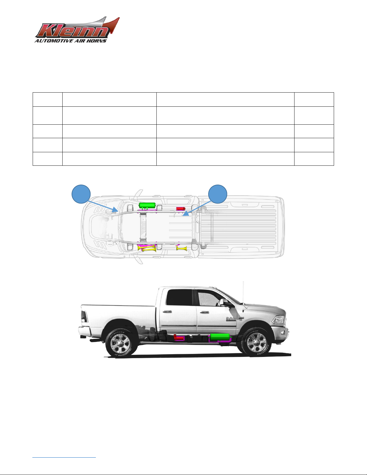
3. Kit Installation Overview ....................................................................................................................................3
3.1. Approximate Installation Time ...................................................................................................................3
4. List of Tools and Supplies ...................................................................................................................................4
4.1. Standard Tool List (Required) .....................................................................................................................4
4.2. Special Tool List (Recommended) ..............................................................................................................4
4.3. Shop Consumables List (Recommended) ...................................................................................................4
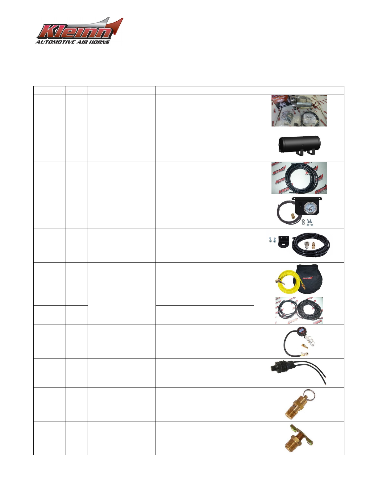
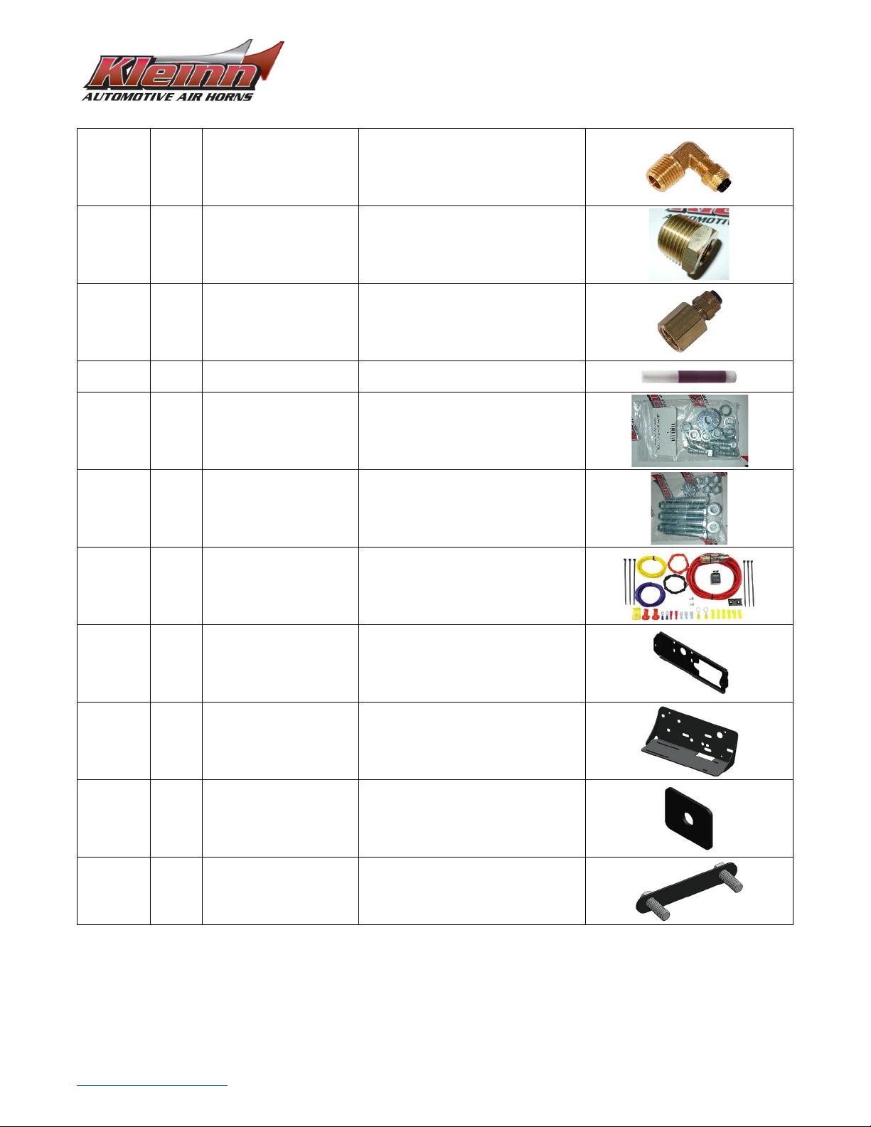
5. Parts List .............................................................................................................................................................5
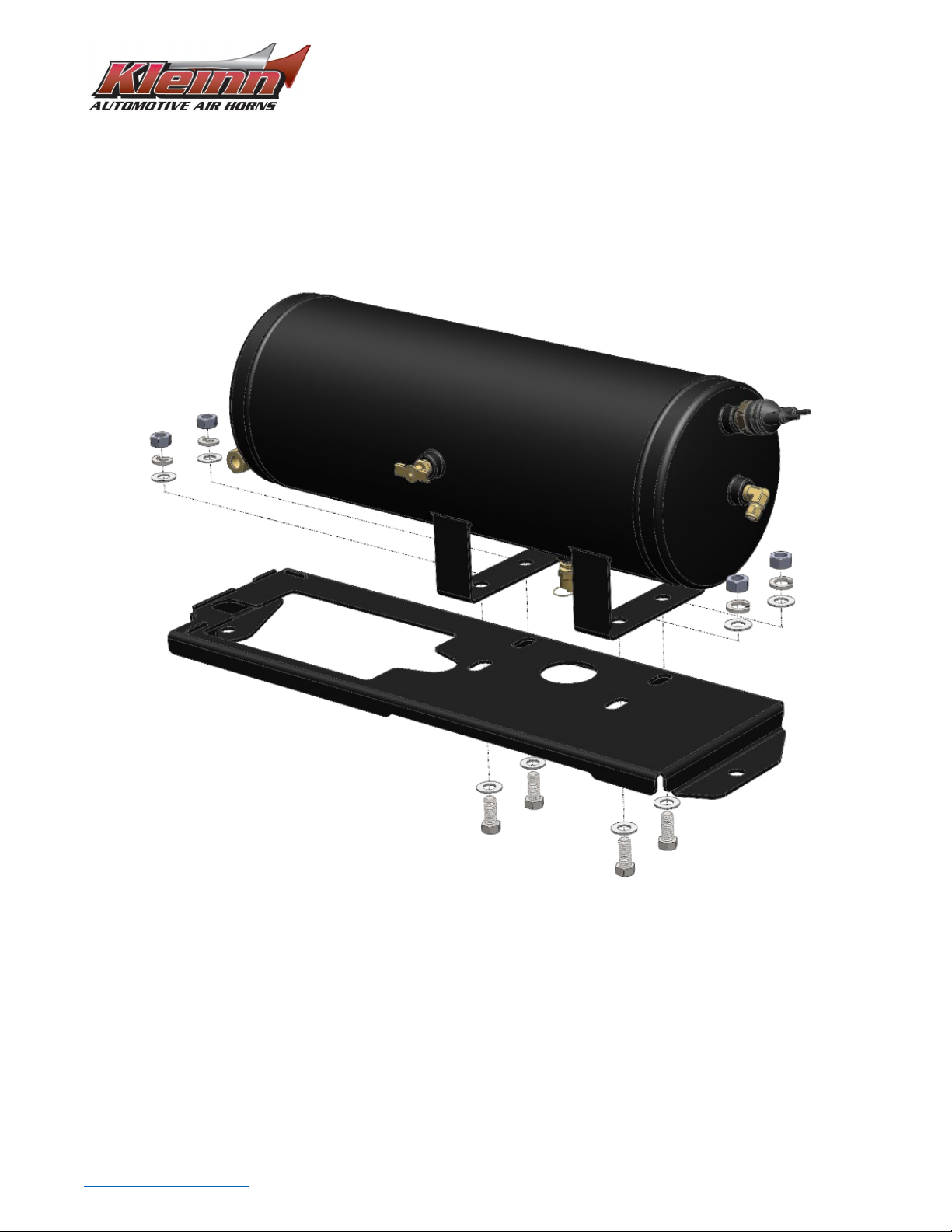
6. Bench Assembly Steps........................................................................................................................................7
6.1. Component Layout .........................................................................................................................................7
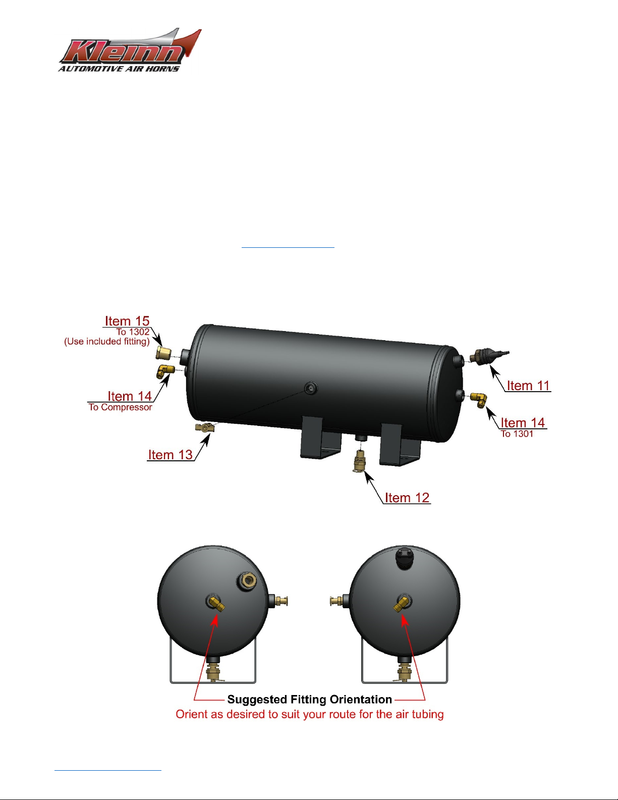
6.2. Air Tank Fittings..............................................................................................................................................7
7. On-Vehicle Assembly..........................................................................................................................................9
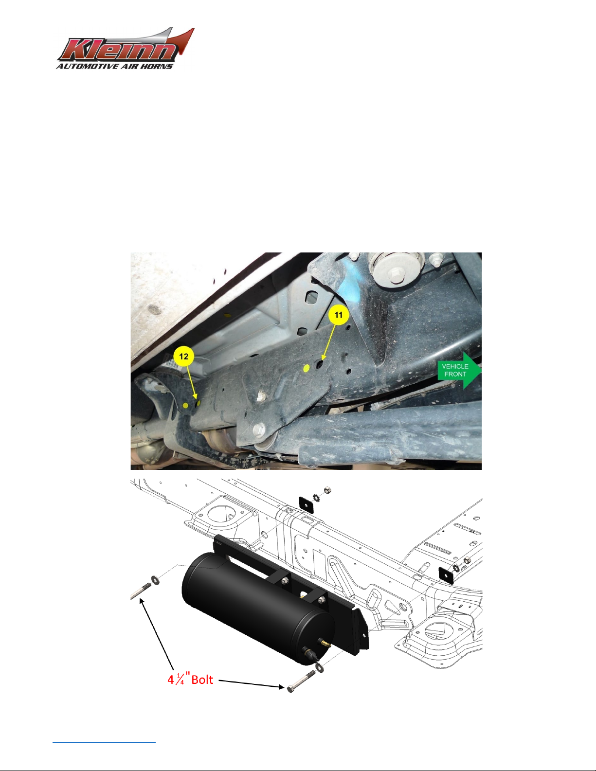
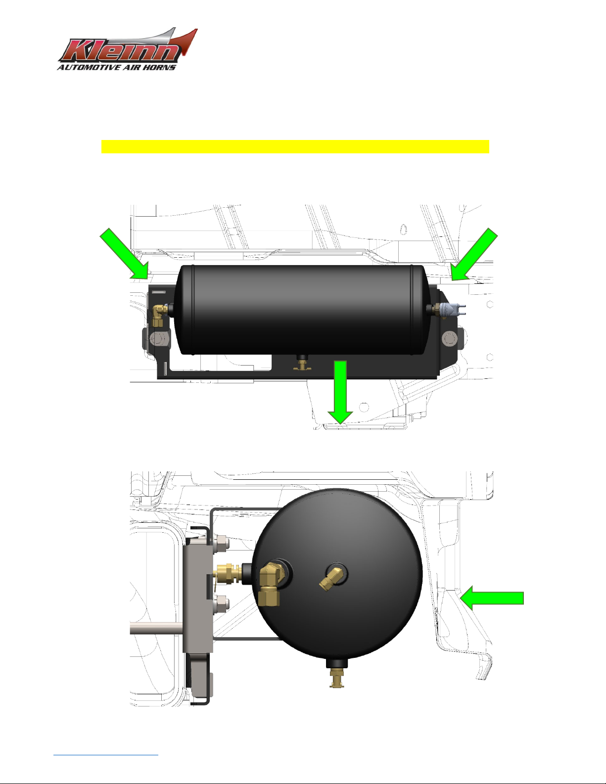
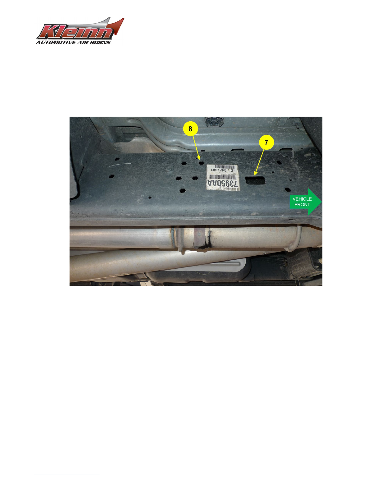
7.1. Air Tank Installation........................................................................................................................................9
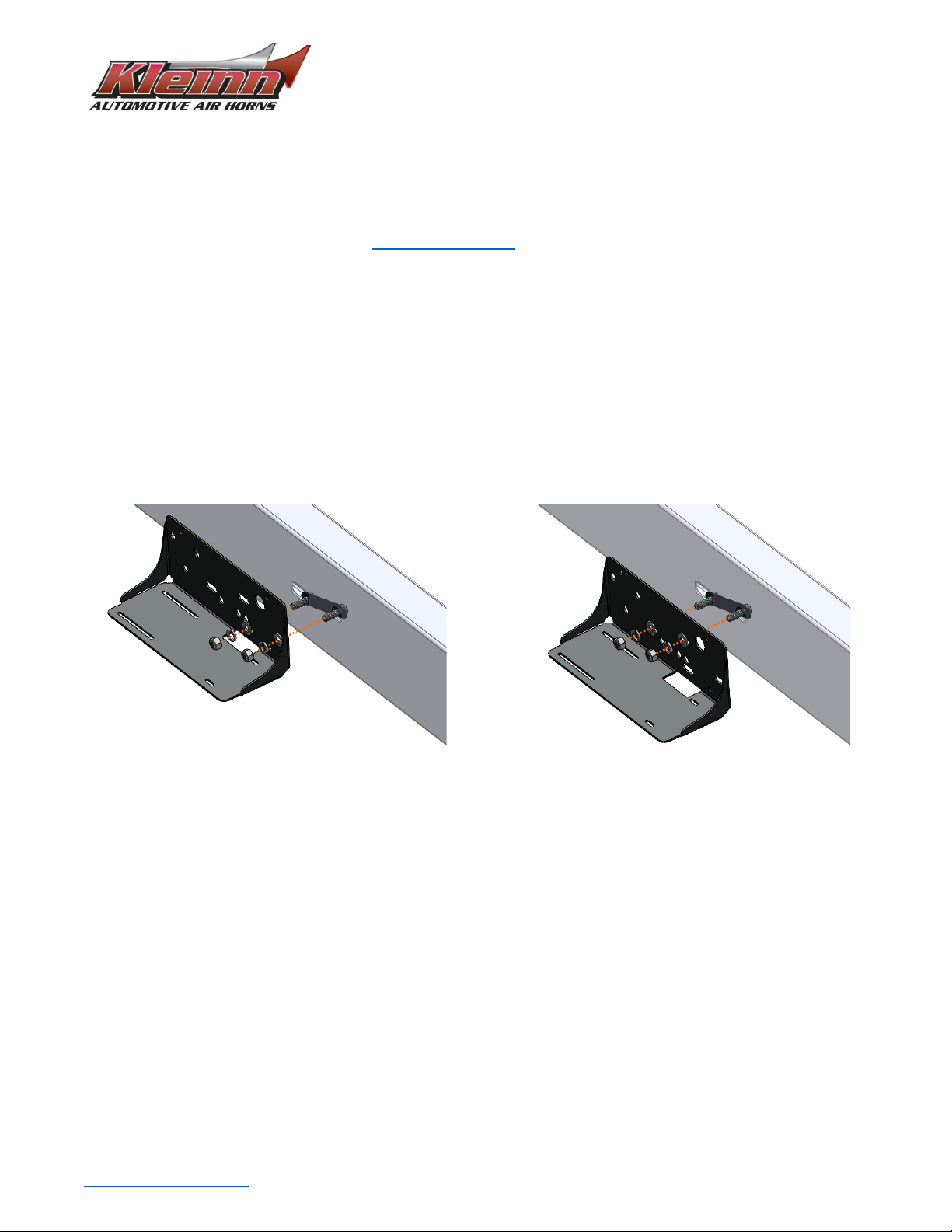
7.2. Compressor & Compressor Bracket Installation ......................................................................................... 11
7.3. 1301 & 1302 Installation ............................................................................................................................. 14
7.4. Air Tubing Routing ....................................................................................................................................... 14
8. On-Vehicle Electrical........................................................................................................................................ 15
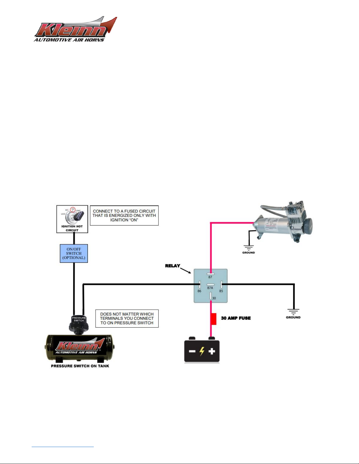
8.1. Relay Installation & Wiring .......................................................................................................................... 15
9. Initial Test ........................................................................................................................................................ 16
9.1. Troubleshooting – Compressor Does Not Run............................................................................................ 16
9.2. Troubleshooting – Compressor Does Not Shut Off ..................................................................................... 16
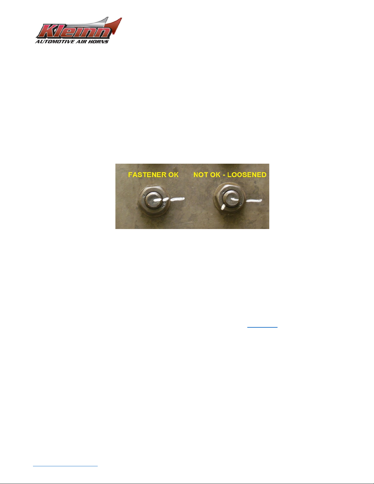
10. Maintenance................................................................................................................................................ 17
10.1. Monthly, or Every 10 Hours of Compressor Run time ............................................................................ 17
10.2. Yearly, or Every 12,000 Miles .................................................................................................................. 17
11. Warranty Information ................................................................................................................................. 18

RAMHDOBA-6450
Install Guide
Go to Table of Contents PG 2/18 REV: A (08/05/2022)
1. Safety First
Read manual thoroughly before starting installation of this kit. Verify you have all parts listed and that you
clearly understand this installation procedure. Contact Kleinn technical support for any questions.
Installation of this kit requires moderate mechanical aptitude; seek professional help if you’re not competent
using hand tools in tight uncomfortable spaces, and around possibly rusted and sharp vehicle parts.
Before starting, obtain proper tools required to perform installation correctly, adequate lighting, eye protection,
hearing protection for operating train horns, and hand protection to guard against sharp edges and metal burrs,
which may be present on kit and vehicle parts.
2. Application Chart
RAMHDOBA-6450 is a bolt-on aftermarket product for all DODGE vehicles listed in below chart.
All vehicles listed may require drilling holes for ground wires and installing switches, based on preference of
switch locations and wire grounding points.
MODEL YR
MODEL
DRIVE
ENGINE
BODY
TRIM
2014-2021
RAM 2500
2WD, 4WD
ALL
Crew Cab (short
bed**), Mega Cab
ALL
2014-2021
RAM 3500
2WD, 4WD,
DUALIE
ALL
Crew Cab (short
bed**), Mega Cab
ALL
**Exclusions:
Crew Cab Long Bed, or Regular/Standard Cab frames; these frames will require drilling holes to attach the
following brackets. Contact Kleinn sales for more information.
Compressor Bracket – Drill holes for mounting hardware.
Product Compatibility:
This kit has been designed and tested to be compatible with leading manufacturers of aftermarket truck steps,
such as Amp Research Power Steps ® and all OEM standard and optional steps.

RAMHDOBA-6450
Install Guide
Go to Table of Contents PG 3/18 REV: A (08/05/2022)
3. Kit Installation Overview
RAMHDOBA-6450 consists of the following major components, located on vehicle per following pictures and
chart
Item No. Component Vehicle Location
Install Time
(Approximate)
1. 6355RT
3.0 Gallon Air Tank
Under passenger side front door.
Bolted to outside of frame rail. 2+ Hours
2.
6450RC
150 PSI Waterproof Compressor
Under passenger side rear door.
Bolted to outside of frame rail.
1-2 Hours
*3.
1301
Illuminated Dash Panel Gauge Kit
Installer/Customer Preference 1+ Hours
*4.
1302
Remote Quick Connect Kit
Installer/Customer Preference 1+ Hours
*Not Illustrated
Top View – Ram 2500 Crew Cab Short Bed
Passenger Side View – 2014 Ram 2500 Crew Cab Short Bed
3.1. Approximate Installation Time
RAMHDOBA-6450 is a multi-faceted product consisting of multiple mechanical, electrical, and pneumatic
components. For a typical home mechanic, or auto enthusiast, a professional installation job with setup and
testing of final product, is estimated to take:
•6+ Hours
2
1

RAMHDOBA-6450
Install Guide
Go to Table of Contents PG 4/18 REV: A (08/05/2022)
4. List of Tools and Supplies
4.1. Standard Tool List (Required)
1. Basic mechanic’s 3/8” drive socket sets with extensions
a. Inch Size Sockets (1/4” – 1” Hex)
b. Metric Size Sockets (6mm – 20mm Hex)
2. Basic mechanic’s combination wrenches (box/open-end)
a. Inch Size Wrenches (1/4” – 1” Hex)
b. Metric Size Wrenches (6mm – 20mm Hex)
3. Basic mechanic’s screwdriver set (Philips, Flat Head)
4. Diagonal Cutter/Wire Cutter Pliers
5. Wire Strippers
6. Wire Terminal Crimpers
7. Slip-Joint Pliers
8. Utility Knife, or Utility Razor blade
4.2. Special Tool List (Recommended)
1. 10-100 ft.-lb. torque wrench
2. 50-150 in.-lb. torque wrench
3. Multi-Meter for 12V DC electrical systems, or equivalent
4. 12V DC Test Light, or equivalent
4.3. Shop Consumables List (Recommended)
1. Quality Electrical tape
2. Di-electric grease for electrical connections
3. Heat Shrink tubing for electrical connections
4. Sandpaper, or Wire Brushes for installing ground wires
5. Extra plastic zip ties > 6” long
6. Extra NPT sealant (i.e., Kleinn Air Horn Juice, Teflon tape, etc.)
7. Touch-up paint for frame/chassis
8. Typical cleanup supplies

RAMHDOBA-6450
Install Guide
Go to Table of Contents PG 5/18 REV: A (08/05/2022)
5. Parts List
RAMHDOBA-6450 includes following items:
Item No.
Qty.
Part Number
Description
Picture
1. 1 6450RC 150 PSI Waterproof Compressor with
hardware & remote air supply
2. 1 6355RT 3.0 Gallon Air Tank
3. 12 Ft 25014-1 1/4” Air Tubing
4. 1 1301 Illuminated Dash Panel Gauge Kit
5. 1 1302 Quick Connect Air Coupler Kit, with
relocation bracket
6. 1 INF-1 Tire Inflation Kit w/ bag & fittings
7. 20 Ft
N/A
Loom Pack – 1/4”
8. 10 Ft Loom Pack – 1/8”
9. 5 Ft Loom Pack – 3/8”
10. 1 59830 Digital Tire Inflator w/ Pressure Release
11. 1 2151 1/4” NPT Pressure Switch
110 PSI On, 145 PSI Off
12. 1 52175 1/4” NPT, 175 PSI Safety Valve
13. 1 52835 Drain Valve
1/4” NPT

RAMHDOBA-6450
Install Guide
Go to Table of Contents PG 6/18 REV: A (08/05/2022)
14. 2 51414L 1/4” NPT X 1/4” Compression Fitting
90 Deg Elbow
15. 1 51214R 1/2” NPT to 1/4” NPT Reducer, Female
16. 1 51414F 1/4” NPT F X 1/4” Compression Fitting
17. 1 JUICE Thread Sealant for NPT Fittings
18. 1 N/A 4-Bolt Tank Hardware:
7/16”-14 Bolts, Nuts, and Washers
19. 1 N/A
Hardware Pack:
1/2”-13 Bolts, Nuts and Washers
7/16-14 Nuts and Washers
20. 1 6852 Compressor Wiring Kit, Complete
21. 1 RAMHD_TANK_BRKT-ASSY Air Tank Bracket
22. 1 RAMHD-200 Air Compressor Bracket
23. 3 RAMHD_WASHER Washer for Frame Slots
24. 1 RAMHD-201
(for 2019+ RAMHD) Compressor Bracket Bolt Tie

RAMHDOBA-6450
Install Guide
Go to Table of Contents PG 7/18 REV: A (08/05/2022)
6. Bench Assembly
Complete following steps off vehicle to facilitate final installation.
6.1. Component Layout
Unpackage RAMHDOBA-6450 and verify all parts are included per above Parts List. Contact Kleinn support if any
questions arise.
6.2. Air Tank Fittings
1. Attach and tighten air fittings to tank, per the below illustrations.
a. Apply two small drops of Kleinn Air Horn Juice to each male pipe thread.
b. Hand-tighten each fitting, then further tighten each 1/4-1/2 turn using proper sized combination
wrench (or equivalent); adjust as necessary to match fitting orientation shown.

RAMHDOBA-6450
Install Guide
Go to Table of Contents PG 8/18 REV: A (08/05/2022)
2. Attach air tank to bracket, per below illustration.
a. Use 4 Bolt Tank Hardware kit
i. Assemble fasteners clean and dry; tank should not move freely, but can be repositioned
with some hand force.
ii. Final tightening will be completed on vehicle.

RAMHDOBA-6450
Install Guide
Go to Table of Contents PG 9/18 REV: A (08/05/2022)
7. On-Vehicle Assembly
DANGER:Installation requires being underneath vehicle and applying forces to vehicle chassis. Follow all
recommended safety precautions for working under the vehicle.
7.1. Air Tank Installation
WARNING:Installing air tank onto vehicle chassis requires hands to be near exhaust system; make sure
vehicle exhaust is cool enough to touch before installation.
1. Attach Air Tank assembly onto vehicle chassis, per below illustration.
a. Use the Hardware Pack. Ensure the bracket is sitting flush on the chassis and finger tighten the
fasteners.

RAMHDOBA-6450
Install Guide
Go to Table of Contents PG 10/18 REV: A (08/05/2022)
Crew Cab and Mega Cab Orientation
2. Position bracket properly and tighten fasteners, per the below illustrations.
a. Move bracket up/down, and fore/aft, as necessary to ensure adequate clearance around tank.
i. Air Tank must have minimum 1/4” clearance between underbody and rocker panels.
ii. Reposition Tank up/down on bracket slots, if necessary.
b. Hold bracket in correct position and tighten mounting fasteners firmly.
c. Tighten tank mounting fasteners to bracket firmly.
Crew Cab and Mega Cab Orientation

RAMHDOBA-6450
Install Guide
Go to Table of Contents PG 11/18 REV: A (08/05/2022)
7.2. Compressor & Compressor Bracket Installation
2019+ RAMHD – Follow the supplemental instructions at the end of this sub-section.
1. Attach the compressor bracket onto vehicle chassis, per the below illustration using the associated parts
of the Hardware Pack.
a. Ensure bracket is parallel to frame (i.e., level).
b. Hold bracket in position and firmly tighten fasteners.
Crew Cab Orientation

RAMHDOBA-6450
Install Guide
Go to Table of Contents PG 13/18 REV: A (08/05/2022)
2. Attach the compressor to the bracket (shown above) using the hardware included within the
compressor box.
a. Tighten fasteners firmly.
3. Attach Item # 16 (NPT F Compression Fitting) to the end of compressor hose, per above illustration
a. Apply two small drops of Kleinn Air Horn Juice to the male pipe thread.
b. Hand-tighten, then further tighten ¼ turn using proper sized combination wrench
2019+ RAMHD:
For 2019+ RAMHD use the compressor bracket and bolt tie-plate to attach the compressor bracket to the frame.
Insert one end of the bolt tie-plate through the square hole. One bolt sticks out of this square hole, the other
bolt sticks out of the round hole just in front of it. Use your fingers to hold the tie plate against the inside of the
frame tube via the square thru-hole. Attach bracket to frame using bolt tie-plate and 7/16" hardware supplied,
as shown below.
Use one of the sets of slots as shown below. Use the forward set of slots (left image below) if your truck has the
rear floor-pockets.
2019+ RAMHD

RAMHDOBA-6450
Install Guide
Go to Table of Contents PG 14/18 REV: A (08/05/2022)
7.3. 1301 & 1302 Installation
Install the 1301 & 1302 onto the vehicle in your desired location.
1. Ensure there is adequate room for the component & air tubing to be routed.
2. Verify there will be no interference from any moving parts before final installation onto the vehicle.
7.4. Air Tubing Routing
Use the supplied air tubing and route as desired to the fittings. Ensure the air tubing is away from sharp edges
and hot vehicle parts. Secure tubing to vehicle using zip ties, or equivalent.
1. Connect air compressor outlet to the air tank compression fitting using the supplied ¼” tubing.
2. Connect the 1301 to the air tank compression fitting using the included fittings and supplied tubing.
3. Connect the 1302 Remote Quick Connect kit to air tank reducer using the NPT fitting included with the
1302
4. Connect the remote air compressor filter kit (included with compressor) and route, as desired. Ensure
the filter is installed in location away from road spray, water, excessive dust, etc.

RAMHDOBA-6450
Install Guide
Go to Table of Contents PG 15/18 REV: A (08/05/2022)
8. On-Vehicle Electrical
It is recommended to disconnect the vehicle battery and follow all recommended safety precautions when
working on vehicle electrical systems.
8.1. Relay Installation & Wiring
Wire the relay and compressor using the included wiring kit. The below figure illustrates the proper connections
to be made.
1. The relay can be mounted to the vehicle using the supplied self-tapping screws.
2. If multiple batteries exist on vehicle, it’s recommended to use the secondary battery.
3. Wiring should be routed through the appropriately sized loom.
4. It is recommended to only cut wires to length when you are 100% confident of the routing and wire
length required.
CAUTION: Do not install fuse provided until all electrical connections are final.
CAUTION:Before connecting vehicle battery(s), verify all wiring is properly connected and no
shorts exists. Use of Multi-Meter, or Test Light is recommended to check continuity of
all connections.

RAMHDOBA-6450
Install Guide
Go to Table of Contents PG 16/18 REV: A (08/05/2022)
9. Initial Test
1) Turn vehicle on and allow compressor to fill the air tank.
a) Initial fill may take up to 3 minutes.
b) Air compressor will shut off automatically once maximum pressure is achieved.
9.1. Troubleshooting – Compressor Does Not Run
If the compressor does not run, perform the following (if wired using the above figure):
1) Verify the fuse is installed on the main compressor power line.
2) Verify the relay clicks when power is applied to the system (depressurized).
3) Check continuity between the relay Pin 85 & any grounding point.
4) Check continuity between the compressor ground and any grounding point.
If the relay does not click when power is applied to the system, review all electrical connections going from the
ignition “ON” circuit to the Relay Pin 86
Solid grounding points are required to for optimal performance of this kit. It is recommended to clean grounding
points down to bare metal for optimal system performance.
9.2. Troubleshooting – Compressor Does Not Shut Off
If compressor runs excessively (5+ minutes), Disconnect power to the air compressor and perform the following:
1) Check the 1301 Gauge (if installed) to identify what PSI the system is at.
2) Listen for air leaks.
3) Check for air leaks by spraying a soap & water solution directly on all fittings. Fittings or areas that
contain leaks will form bubbles where the leak is.
The system is designed to start the compressor at 110 PSI or lower & cut off power to the compressor at 145 PSI.
If leaks are found, it is recommended to depressurize the system by using the drain valve and disassemble,
clean, re-seal and reassemble the leaking fitting.
WARNING:Never operate Air Compressor above its MAXIMUM PRESSURE RATING (see label on
body). Operation exceeding maximum pressure will damage air compressor and may result in
dangerous air system failure.
Your air compressor is equipped with an automatic thermal overload protection circuit, designed to protect the
compressor from overheating and causing permanent damage.
Thermal overload protection will automatically reset after 30 minutes.
To prevent discharge of your vehicle’s battery & for best performance, keep the engine running while using the
air compressor for prolonged use.

RAMHDOBA-6450
Install Guide
Go to Table of Contents PG 17/18 REV: A (08/05/2022)
10. Maintenance
Perform the following steps at least once during recommended intervals.
10.1. Monthly, or Every 10 Hours of Compressor Run time
1. Drain moisture from the tank using the installed drain valve.
Failure to regularly drain the air tank may result in corrosion inside tank and possible failure of
the tank or air tubing.
10.2. Yearly, or Every 12,000 Miles
1. Verify all mounting fasteners are not loose. Applying witness marks on fasteners and mounting areas is
good practice and can be used to quickly check if fasteners have moved.
2. Remove road grime and debris from mounting brackets and kit parts using clean water. Do this more
frequently if traveling regularly off-road, or in winter climates where road salts are used
NOTE: Pressure washers may damage part finishes and must be used with care.
3. Touch up paint chips using automotive grade enamel.
4. Check electrical connections, air fittings and wiring for abrasion, corrosion, or other damage. Replace
damaged components as needed.
5. Clean, or replace air filter element. Replacement frequency depends on operating frequency and
conditions of the operating environment. Order replacement filters at Kleinn.com.
NOTE: Never lubricate or add any liquids to the air compressor.

RAMHDOBA-6450
Install Guide
Go to Table of Contents PG 18/18 REV: A (08/05/2022)
11. Warranty Information
Thank you for purchasing this RAMHDOBA-6450. If you experience any unexpected problems during
installation, or have problems with any part, at any time, please contact Kleinn support.
© Kleinn Air Horns 2021, All rights reserved.
PO Box 91278 Tucson, AZ 85752
Phone: (520) 579-1531
Web: www.Kleinn.com
Other manuals for RAMHDOBA-6450
1
Table of contents
Other Kleinn Automobile Accessories manuals
Popular Automobile Accessories manuals by other brands

Alpine
Alpine i509-WRA-JK installation manual

Alpine
Alpine HCE-C117D owner's manual

Whelen Engineering Company
Whelen Engineering Company CEM8 installation guide

Retrax
Retrax EQ quick start

Superior Engineering
Superior Engineering SUP-200MOD installation instructions

AA Products
AA Products APX2503 instruction manual