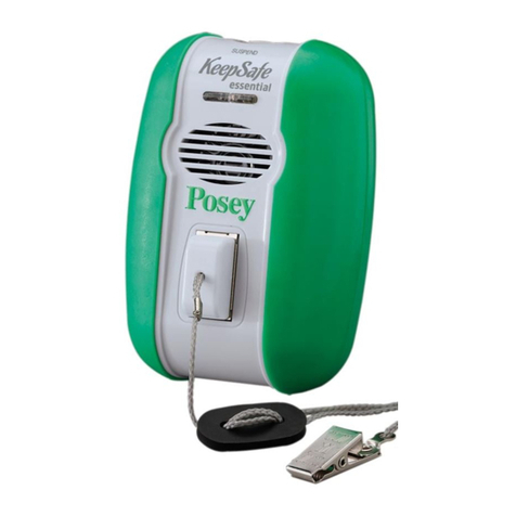
chair Pad sensor instructions
1. PlacetheChairPadSensoracross
the width of the seat directly under
the patient’s buttocks. If a seat
cushionisused,placethepadON
TOPofthecushion.
2. Plug the Chair Pad Sensor into the
receptacle (4) on the side of the alarm.
Thecableshouldbekeptawayfromall
moving parts on the chair to avoid damage.
Always verify you can hear the alarm
volume at the furthest possible
distancebeforeleavingpatient/resident
unattended. Neverplacethealarmunit
closer than two feet from the ear.
System Test
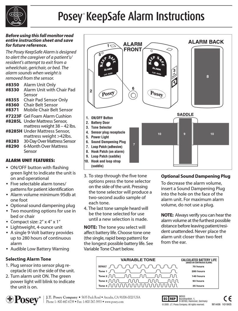
1.Plugsensorintoalarmunit.
2.Turnalarmunitonandverifypower
lightislit.Theunitwillautomatically
begin monitoring after it first senses
weight on the sensor.
3. Check to make sure the audio alarm is
functioning properly by lifting weight off
the sensor pad and activating the alarm.
NOTE: If the sensor is disconnected
while in use, the alarm will sound to
notify the caregiver.
alarm unit mounting
instructions - saddle mount
1. Chooseasecurelocationoutof
thepatient’s/resident’sreach,
preferably in the rear, below the chair
seat(Figure1).
2. Wrapthesaddlestrapfirmlyarounda
bar of the wheelchair or bed frame.
3. Be sure the saddle is securely in place
and will not move.
4. Attach the hook material on the
alarm unit to the loop material on the
saddle by firmly pressing the alarm
unit to the saddle (Figure 2).
5. Alwaysconfirmproperattachment
before each use. Ensure that the alarm
unit and sensor cables are clear of all
moving parts of the chair.
PoseyCompany•5635PeckRoad,Arcadia,CA91006-0020USAPhone:1.800.447.6739•Fax:1.800.767.3933•Web:www.posey.com
mobiLe cHair beLt - 8370
Hook and Loop Mount -
1. Choosesiteonheadboardorother
mounting surface, i.e. nightstand or
toilet, out of patient’s reach.
2. Clean site with alcohol wipe and let it
dry.
3.Attachself-adhesiveloop(fuzzy)
patch(7)bypeelingoffbackingand
pressing into place on the mounting
surface.
NOTE: Adhesive on loop will not
adhere to vinyl, or similar surface.
4. Press the hook (rough) patch (8) on
the back of the alarm firmly to the
loop patch on mounting surface.
Fig. 1 Wheelchair Mount attached to lower,
rear wheelchair frame
Fig. 2
Always check the mounting before
each use, making sure the alarm is
functioning properly and is securely
positioned.
Cleaning Instructions
• AlarmUnit–Wipecleanwithmild
disinfectant. Do not submerge in
liquidorsterilizewithheat.
• SaddleMount–Wipecleanwith
mild disinfectant.
• HookandLoop–Usestiffbrushto
remove dust and lint.
• Readsensorandalarminstructions
prior to use.
• NeverconnectPoseysensorsto
other manufacturers’alarm units.
• Neverconnectothermanufacturers’
sensors to Posey alarm units.
• Alwaystestsystemperinstructions
prior to use.
• Besurerestraintstrapsdonotcross
oversensorpad!Restraintstraps
may prevent alarm activation if
patient falls out of bed or chair.
• Thisdevicemaynotbesuitablefor
usewithall“highfallrisk”patients.
• Thisdeviceshouldnotbea
substitute for maintaining the
routine visual monitoring protocol
by healthcare personnel.
• Thealarmmayfailtosoundifthe
pad is bent or folded.
Battery Replacement
Thealarmunitwillemitanaudible
chirpindicatinga“LowBattery”.To
replacethebattery:
1. Turnalarmunitoff.
2. Press down on arrow and slide
battery door open.
3. Disconnect terminal cap to remove
battery.
4. Connect terminal cap to new battery
and insert into alarm unit.
5. Slidebatterydoorclosed.
6. Verifysystemisworkingbefore
leaving resident unattended.
limited lifetime Warranty:
ThePoseyCompanywarrantstothe
original purchaser, the alarm unit
to be free from defects in materials
and workmanship for the life of the
unit.Warrantyvoidifunitisopened,
damaged,orsubmerged.Thiswarranty
gives you specific legal rights, and you
may also have other rights, which vary
from state to state.


