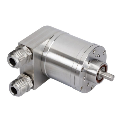
POSITAL OCD-EI-A1B-0013-C100-PRM User manual

Absolute Rotary Encoder
with PROFINET-IO-Interface
OCD-EIA1B-XXXX-XXXX-PRM
User Manual

Info UME-EI
Revision 11/09
Page 2
ABSOLUTE ROTARY ENCODER WITH PROFINET INTERFACE
USER MANUAL
Content
Content.............................................................2
1. Introduction .................................................4
1.1 Absolute rotary encoder...........................4
1.2 PROFINET technology ............................5
1.3 Features of the Encoder ..........................5
2. Installation ...................................................6
2.1 Electrical Connection...............................6
2.2 Ethernet cables........................................6
2.2.1 RJ45 –M12 crossed.............................6
2.2.2 RJ45 –M12 straight..............................6
2.2.3 M12 –M12 crossed ..............................6
2.3 Diagnostic LEDs ......................................7
2.4 Status LED indication...............................7
2.5 Instructions for mechanical installation and
electrical connection of the rotary encoder ....8
3. Device configuration...................................9
3.1 Standardization........................................9
3.2 Encoder Classes......................................9
3.3 Encoder functions..................................10
3.4 Signal list for Cyclic Data Transmission.10
3.4.1 Format of actual position values .........11
3.4.2 Encoder control word (STW2_ENC)...12
3.4.3 Encoder status word (ZSW2_ENC) ....12
3.4.4 Encoder control word (G1_STW)........13
3.4.5 Encoder status word (G1_ZSW).........13
3.5 Standard telegrams................................14
3.6 Configuration principle...........................15
3.7 Rotary encoder functionality overview ...15
3.8 Rotary encoder functions –data format .15
3.8.1 Base Mode Parameter ........................16
3.8.2 Device Parameter ...............................16
3.8.3 Vendor Parameter...............................16
3.9 Rotary encoder function description.......19
3.9.1 Code sequence...................................19
3.9.2 Class 4 functionality ............................20
3.9.3 Preset control for G1_XIST1...............20
3.9.4 Scaling function control.......................20
3.9.5 Alarm channel control .........................20
3.9.6 Preset value........................................21
3.9.7 Offset value.........................................22
3.9.8 Scaling parameters .............................22
3.9.9 Max. Master Sign-Of-Life failures........22
3.9.10 Velocity measuring units ...................22
3.9.11 Velocity filter......................................23
3.9.12 Endless Shaft (RoundAxis) ...............23
4. Configuring with STEP7............................24
4.1 Installing the GSDML file........................24
4.2 Engineering a POSITAL encoder into a
STEP7 project..............................................25
4.3 LLDP (Link Layer Discovery Protocol) ...27
4.4 Selecting an encoder version.................29
4.4 Setting encoder parameters...................30
4.5 Changing and reading encoder
parameters at run-time.................................30
4.6 Setting of device properties....................31
4.7 Sample of Variable table........................32
4.8 IRT settings............................................33

Info UME-EI
Revision 11/09
Page 3
ABSOLUTE ROTARY ENCODER WITH PROFINET INTERFACE
USER MANUAL
4.9 Fast Start up..........................................33
5. Configuring with PC Worx........................34
Installing the GSDML file .............................34
6 FAQ..............................................................40
7 Technical data ............................................42
7.1 Electrical data ........................................42
7.2 Mechanical data.....................................42
7.3 Minimum (mechanical) lifetime ..............43
7.4 Environmental Conditions......................43
8 Mechanical Drawings.................................44
8.1 Synchro Flange (S)................................44
8.2 Clamp Flange (F)...................................44
8.3 Hollow shaft (B)......................................45
9 Models / Ordering Description ..................46
10 Accessories and Documentation............47
11 Glossar......................................................48
12 Revision index ..........................................49

Info UME-EI
Revision 11/09
Page 4
ABSOLUTE ROTARY ENCODER WITH PROFINET INTERFACE
USER MANUAL
Imprint
POSITAL GmbH
Carlswerkstrasse 13c
D-51063 Köln
Telephone +49 (0) 221 96213-0
Fax +49 (0) 221 96213-20
Internet http://www.posital.eu
Copyright
The company POSITAL GmbH claims copyright on
this documentation. It is not allowed to modify, to
extend, to hand over to a third party and to copy
this documentation without written approval by the
company POSITAL GmbH. Nor is any liability
assumed for damages resulting from the use of the
information contained herein. Further, this
publication and features described herein are
subject to change without notice.
Alterations of specifications reserved
Technical specifications, which are described in
this manual, are subject to change due to our
permanent strive to improve our products.
Disclaimer of Warranty
POSITAL GmbH makes no representations or
warranties, either express or implied, by or with
respect to anything in this manual, and shall not be
liable for any implied warranties of merchantability
and fitness for a particular purpose or for any
indirect, special, or consequential damages.
Version date: November 18, 2009
Version number: 2.08
Article number: n/a
Author: Reiner Bätjer
1. Introduction
This manual describes the implementation and
configuration of an absolute rotary encoder with
PROFINET interface. The device fulfills the
requirements of a PROFINET IO device with RT
(real time) or IRT (isochronous real time)
classification.
1.1 Absolute rotary encoder
The basic principle of an absolute rotary encoder is
the optical sampling of a transparent code disc
which is fixed with the driving shaft.
The absolute rotary encoder has a maximum
resolution of 65,536 steps per revolution (16 bits).
The mutli-turn version can detect up to 16,384
revolutions (14 bits). Therefore the largest resulting
resolution is 30 bits = 230 = 1,073,741,824 steps.
The standard single-turn version has 13 bits, the
standard multi-turn version 25 bits.
For further information about the function principle
or the setup of a PROFINET network please, refer
to http://www.profibus.com/pn.

Info UME-EI
Revision 11/09
Page 5
ABSOLUTE ROTARY ENCODER WITH PROFINET INTERFACE
USER MANUAL
1.2 PROFINET technology
PROFINET is an Industrial Ethernet standard
merging plant automation with other enterprise IT
resources.
It provides comparable functionality to PROFIBUS
with techniques used by engineering, IT, and
management personnel.
Established IT standards are employed as basis of
communication: TCP, UDP, IP. XML is used as
description language for device profiles (GSDML
files).
Two ways of using PROFINET are available:
PROFINET IO, similar to PROFIBUS DP as a
distributed I/O system and PROFINET CBA as a
modular component-based system for larger
systems.
PROFINET offers scalable communication for
different applications in industrial automation:
PROFINET NRT (non real time) is suited
for non-time-critical process automation
with clock rates of roughly 100 msec.
PROFINET RT (real time) offers a
communication channel with optimized
performance (10 msec clock rate) for
most factory automation tasks
PROFINET IRT (isochronous real time)
employs special communication hardware
to enable clock rates of less than 1 msec
and a jitter precision of less than 1 µsec.
This channel is mainly of use for motion
control applications.
PROFINET IO uses a view of distributed I/O similar
to PROFIBUS DP. IO controllers (e.g. PLCs) run
an automation program, IO devices (e.g. absolute
encoders) are remotely assigned field devices, and
IO supervisors (e.g. programming devices) are
used for commissioning and diagnostics.
The engineering of PROFINET IO is done similar
to PROFIBUS. The field buses (i.e. Ethernet
topologies) are assigned to control systems during
configuration. The IO device is configured in the
actual system based on the contents of its GSDML
file.
After completion of the engineering the installer
loads the data for the expansion into the IO
controller (PLC) and the IO controller assumes
data exchange with the IO device.
An IO device is addressed within PROFINET (and
also possibly by external IT components) through
its IP address.
Data can be exchanged from the IO controller to
the IO device (and vice versa) cyclically (for
process data). Apart from this, parameter data can
be exchanged acyclically during engineering of the
IO device or by the use of PLC programming
blocks.
1.3 Features of the Encoder
Integrated Boot loader for customer
firmware upgrades
Round axis (Endless shaft)
Neighboring detection
Engineering identification call
Different filters for velocity
Used Profinet Encoder Profile V4

Info UME-EI
Revision 11/09
Page 6
ABSOLUTE ROTARY ENCODER WITH PROFINET INTERFACE
USER MANUAL
2. Installation
2.1 Electrical Connection
The rotary encoder is connected by a 4 pin M12
connector for the power supply and two 4 pin,
D-coded M12 connector for Ethernet.
The Encoder uses a second D-coded connector
and provides integrated switch functionality. On or
in the packaging of the connector is the mounting
description.
Connector Ethernet
4 pin female, D-coded Connector power supply
4 pin male, A-coded
2.2 Ethernet cables
2.2.1 RJ45 –M12 crossed
Signal
RJ45 Pin
M12 Pin
Tx+
1
2
Tx-
2
4
Rx+
3
1
Rx-
6
3
2.2.2 RJ45 –M12 straight
Signal
RJ45 Pin
M12 Pin
Tx+
1
1
Tx-
2
3
Rx+
3
2
Rx-
6
4
2.2.3 M12 –M12 crossed
Signal
M12 Pin
M12 Pin
Tx+
1
1
Tx-
2
2
Rx+
3
3
Rx-
4
4
Pin Number
Signal
1
Tx +
2
Rx +
3
Tx -
4
Rx -
Sketch on encoder view
2
3
1
4
Pin Number
Signal
1
US (10 - 30 V DC)
2
N.C.
3
GND (0V)
4
N.C.
1
4
2
3
5

Info UME-EI
Revision 11/09
Page 7
ABSOLUTE ROTARY ENCODER WITH PROFINET INTERFACE
USER MANUAL
2.3 Diagnostic LEDs
LED
Color
Description for LED = on
Active1
Yellow
Incoming and outgoing traffic for port 1
Link1*
Green
Link to another Ethernet component for port 1
Active2
Yellow
Incoming and outgoing traffic for port 2
Link2*
Green
Link to another Ethernet component for port 2
Stat1
Green
Status 1, details in the next table
Stat2
Red
Status 2, details in the next table
* Flashes with 2Hz if engineering identification call is activated and link connection is available
2.4 Status LED indication
Status 1
Green
Status 2
Red
(Bus failure)
Meaning
Cause
Off
Off
No power
On
On
No connection to another device
Criteria: no data exchange
- bus disconnected
- Master not available / switched off
On
Blinking 1)
Parameterization fault, no data
exchange
Criteria: data exchange correct.
However, the slave did not switch
to the data exchange mode.
- Slave not configured yet or wrong
configuration
- Wrong station address assigned
(but not outside the permitted range)
- Actual configuration of the slave
differs from the nominal configuration
On
Off
Data exchange.
Slave and operation ok.
1) The blinking frequency is 0.5 Hz. Minimal indication time is 3 sec.

Info UME-EI
Revision 11/09
Page 8
ABSOLUTE ROTARY ENCODER WITH PROFINET INTERFACE
USER MANUAL
2.5 Instructions for mechanical installation and electrical connection of the rotary encoder
The following points should be observed:
Do not drop the angular encoder or
subject it to excessive vibration. The
encoder is a precision device.
Do not open the angular encoder housing
(this does not mean that you cannot
remove the connection cap). If the device
is opened and closed again, it can be
damaged and dirt may enter the unit.
The angular encoder shaft must be
connected to the shaft to be measured
through a suitable coupling (full shaft
version). This coupling is used to dampen
vibrations and imbalance on the encoder
shaft and to avoid inadmissible high
forces. Suitable couplings are available
from Posital.
Although Posital absolute encoders are
rugged, when used in tough ambient
conditions, they should be protected
against damage using suitable protective
measures. The encoder should not be
used as handles or steps.
Only qualified personnel may commission
and operate these devices. These are
personnel who are authorized to
commission, ground and tag devices,
systems and circuits according to the
current state of safety technology.
It is not permissible to make any electrical
changes to the encoder.
Route the connecting cable to the angular
encoder at a considerable distance or
completely separated from power cables
with their associated noise. Completely
shielded cables must be used for reliable
data transfer and good grounding must be
provided. Cabling, establishing and
interrupting electrical connections may
only be carried-out when the equipment is
in a no-voltage condition. Short-circuits,
voltage spikes etc. can result in erroneous
functions and uncontrolled statuses which
can even include severe personnel injury
and material damage.
The encoder should have got a large-area
connection to PE. If the flange don’t have
a good electrical connection to the
machine –i.e. if there was used a plastic
mounting device –then use i.e. a 30cm
long and 2cm wide copper tape to get the
PE connection.
Before powering-up the system, check all of the
electrical connections. Connections, which are not
correct, can cause the system to function
incorrectly. Fault connections can result in severe
personnel injury and material damage.

Info UME-EI
Revision 11/09
Page 9
ABSOLUTE ROTARY ENCODER WITH PROFINET INTERFACE
USER MANUAL
3. Device configuration
3.1 Standardization
This actual generation of PROFINET devices is
based on the Encoder Profile V4 (PNO No.
3.162). With this standardization it is possible to
substitute all products that fulfill the specification.
See the next figure with the coherences.
3.2 Encoder Classes
Application Class
Description
3
Isochronous mode is not supported (RT)
4
Isochronous mode is supported (IRT)

Info UME-EI
Revision 11/09
Page 10
ABSOLUTE ROTARY ENCODER WITH PROFINET INTERFACE
USER MANUAL
3.3 Encoder functions
Implementation
Function
Class 3
Class 4
Code sequence
-/*
Class 4 functionality
G1_XIST1 Preset control
-/*
Scaling function control
-/*
Alarm channel control
Preset value
-/*
Preset value 64bit
-
-
Measuring units per revolution / Measuring step
-/*
Total measuring range
-/*
Measuring units per revolution 64bit
-/*
Total measuring range 64bit
-/*
Maximum Master Sign-Of-Life failures
-/*
Velocity measuring unit
-/*
Encoder Profile version
Operating time
-
-
Offset value
-/*
Offset value 64 bit
-/*
Round axis (Endless shaft)
Velocity filter
* If Class 4 functionality is activated
3.4 Signal list for Cyclic Data Transmission
Signal
No.
Significance
Abbreviation
Lenght
(bit)
Sign
3
Master’s sign-of-life
STW2_ENC
16
-
4
Slave’s sign of life
ZSW2_ENC
16
-
6
Velocity value A
NIST_A
16
8
Velocity value B
NIST_B
32
9
Control word
G1_STW
16
-
10
Status word
G1_ZSW
16
-
11
Position value 1
G1_XIST1
32
-
12
Position value 2
G1_XIST2
32
-
39
Position value 3
G1_XIST3
64
-

Info UME-EI
Revision 11/09
Page 11
ABSOLUTE ROTARY ENCODER WITH PROFINET INTERFACE
USER MANUAL
3.4.1 Format of actual position values
G1_XIST1 and G1_XIST2 are the actual position
values in binary. For absolute encoders one
format example is given below. NOTE: the
alignment in the data-frame (left or right-aligned)
is considered for each individual resolution.
Example: 25 bit Multiturn absolute encoder
(8192 steps per revolution, 4096 distinguishable
revolutions).
All values are presented in binary format
The shifting factors in P979 "sensor format"
display the actual format. The default setting is
G1_XIST1 left aligned and G1_XIST2 right
aligned.
The settings in the Encoder parameter data
affect the position value in both G1_XIST1 and
G1_XIST2.
G1_XIST2 displays the error telegram instead
of the position value if error occurs.
P979, Subindex 3 (Shift factor for G1_XIST1)
= 7
P979, Subindex 4 (Shift factor for G1_XIST2)
= 0
M = Distinguishable Revolutions (Multiturn
value)
S = Pulses (Singleturn steps per revolution)
31
30
29
28
27
26
25
24
23
22
21
20
19
18
17
16
15
14
13
12
11
10
9
8
7
6
5
4
3
2
1
0
M
M
M
M
M
M
M
M
M
M
M
M
S
S
S
S
S
S
S
S
S
S
S
S
S
Absolute value in G1_XIST1
31
30
29
28
27
26
25
24
23
22
21
20
19
18
17
16
15
14
13
12
11
10
9
8
7
6
5
4
3
2
1
0
M
M
M
M
M
M
M
M
M
M
M
M
S
S
S
S
S
S
S
S
S
S
S
S
S
Absolute value in G1_XIST2
G1_XIST3
For 64bit position values is the G1_XIST3 available. The binary value will transmit right aligned and without
shifting factor.
IO Data
1
2
3
4
Format
64 bit position value

Info UME-EI
Revision 11/09
Page 12
ABSOLUTE ROTARY ENCODER WITH PROFINET INTERFACE
USER MANUAL
3.4.2 Encoder control word (STW2_ENC)
4-Bit-counter, left justified. The master
application starts the sign of life with any value
between 1 and 15. The master increases the
counter in every cycle of the master application.
Valid values for the master’s sign of life are 1 to
15, “0” indicates an error and is left out in normal
operation.
Implementation
Bit
Function
Class 3
Class 4
0…9
Reserved, currently not used
10
Control by PLC
11
Reserved, currently not used
12…15
Controller Sign-Of-Life
-
Bit
Value
Significance
Comments
10
1
Control by PLC
Control via interface, EO IO Data is valid
0
No control by PLC
EO IO Data is not valid. Except Sign-Of-Life
12…15
Controller Sign-Of-Life
Send continuous counting value from 0 to 15
3.4.3 Encoder status word (ZSW2_ENC)
4-Bit-counter, left justified. The slave application
starts the sign of life with any value between 1
and 15 after successful synchronization to the
clock pulse. The counter is increased by the
slave application in every DP-cycle. Valid values
for the slave’s sign of life are 1 to 15, “0”
indicates an error and is left out in normal
operation.
Implementation
Bit
Function
Class 3
Class 4
0…8
Reserved, currently not used
9
Control requested
Mandatory
Mandatory
10…11
Reserved, currently not used
12…15
Encoder Sign-Of-Life
-
Mandatory
Bit
Value
Significance
Comments
9
1
Control requested
The automation system is requested to assume control
0
No control by PLC
EO IO Data is not valid. Except Sign-Of-Life
12…15
Encoder Sign-Of-Life
Send back continuous Controller Sign-Of-Life (counting
value from 0 to 15)

Info UME-EI
Revision 11/09
Page 13
ABSOLUTE ROTARY ENCODER WITH PROFINET INTERFACE
USER MANUAL
3.4.4 Encoder control word (G1_STW)
Bit
Value
Function
Comments
0
..
10
Reserved, currently not used
11
0/1
„Home position mode“
Specifies if the position value shall be set to a previously
programmed absolute value or shifted by this value.
0: set home position / preset (absolute)
1: shift home position / preset (relative = offset)
12
1
Set preset / request shift
Preset (resp. shift) is set when changing this Bit to “1” (rising
edge). Default preset value (shift): 0
Warning: After setting the preset the offset will be save in the
non volatile memory. In this 5-10ms the encoder will not send
position values.
13
1
Request absolute value
cyclically
Request of additional cyclic transmission of the absolute actual
position in G1_XIST2. If no other data needs to be transferred
due to commands or errors the absolute position value will be
transmitted automatically.
14
1
Activate parking sensor
If the “activate parking sensor” bit is set, the encoder transmits
no error messages.
15
1
Acknowledging a sensor
error
Request to acknowledge / reset a sensor error
3.4.5 Encoder status word (G1_ZSW)
Bit
Value
Meaning
Comment
0
..
10
Reserved, currently not used
11
Acknowledgement
sensor error in process
Is set if the reset of a sensor error (after acknowledging) takes
longer than one bus cycle.
12
1
Set preset / shift
reference point executed
Acknowledgement for “set preset / request shift”
13
1
Transmit absolute value
cyclically
Acknowledgement for “request absolute value cyclically“
14
1
Parking sensor activated
Acknowledgement for “activate parking sensor“. The encoder
transmits no error messages.
15
1
Sensor error
Indicates a sensor error. A device specific error code is
transmitted in G1_XIST2.

Info UME-EI
Revision 11/09
Page 14
ABSOLUTE ROTARY ENCODER WITH PROFINET INTERFACE
USER MANUAL
3.5 Standard telegrams
Standard Telegram 81
IO Data (DWord)
1
2
Setpoint
STW2_ENC*
G1_STW1*
* Details about the variables are available in chapter 3.4
IO Data
(DWord)
1
2
3
4
5
6
Actual
value
ZSW2_ENC*
G1_ZSW1*
G1_XIST1*
G1_XIST2*
Standard Telegram 82
IO Data (DWord)
1
2
Setpoint
STW2_ENC*
G1_STW1*
IO Data
(DWord)
1
2
3
4
5
6
7
Actual
value
ZSW2_ENC*
G1_ZSW1*
G1_XIST1*
G1_XIST2*
NIST_A*
Standard Telegram 83
IO Data (DWord)
1
2
Setpoint
STW2_ENC*
G1_STW1*
IO Data
(DWord)
1
2
3
4
5
6
7
8
Actual
value
ZSW2_ENC*
G1_ZSW1*
G1_XIST1*
G1_XIST2*
NIST_B*
Standard Telegram 84
IO Data (DWord)
1
2
Setpoint
STW2_ENC*
G1_STW1*
IO Data
(DWord)
1
2
3
4
5
6
7
8
9
10
Actual
value
ZSW2_ENC*
G1_ZSW1*
G1_XIST3*
G1_XIST2*
NIST_B*

Info UME-EI
Revision 11/09
Page 15
ABSOLUTE ROTARY ENCODER WITH PROFINET INTERFACE
USER MANUAL
3.6 Configuration principle
The rotary encoder with PROFINET interface
can be programmed according to the needs of
the user. The GSDML file pertaining to the rotary
encoder has to be installed in the used PLC
engineering software tool.
3.7 Rotary encoder functionality overview
Function
Communication channel
Position value
Cyclic input (IO device -> IO controller)
Preset
Cyclic output (IO controller -> IO device)
Coding sequence
Acyclic input/output
Scaling function
Acyclic input/output
3.8 Rotary encoder functions –data format
PROFINET IO devices are set up in modules.
Each module can be plugged in physical and/or
logical slots. These are subdivided into sub slots
individually to accommodate further data hierarchy.
One sub slot can contain several cyclic
input/output channels as well as acyclic record
channels (used for parameters).
There are two versions of PLC available. Some of
them support only one sub slot. Other ones i.e. S7
400 support several sub slots. To work with both
PLCs there are in the GSDML-file two directories:
Standard and Encoder Profile 4.
POSITAL rotary encoders offer for the standard
profile one slot (address #0) with one sub slot
(address #0) for all device data for old PLC’s that
doesn’t support several sub slots.
Device parameters are grouped together as
records in the PROFINET interface. The following
table gives an overview over addresses of
POSITAL rotary encoder’s data channels.
GSDML file
PLC engineering software PLC
Rotary encoder
Cyclic data
transmission
(process data)
Acyclic data
transmission
(Parameters)

Info UME-EI
Revision 11/09
Page 16
ABSOLUTE ROTARY ENCODER WITH PROFINET INTERFACE
USER MANUAL
Parameter for Acyclic Data Transmission
3.8.1 Base Mode Parameter
Function
Slot
Sub slot
Index
Offset
Length
IO
Code sequence
1
1
0xBF00
0.0
1 Bit
-
Class 4 functionality
1
1
0xBF00
0.1
1 Bit
-
G1_XIST1 Preset control
1
1
0xBF00
0.2
1 Bit
-
Scaling function control
1
1
0xBF00
0.3
1 Bit
-
Alarm channel control
1
1
0xBF00
0.4
1 Bit
-
Measuring units per revolution
1
1
0xBF00
1
8 Byte
-
Total measuring range
1
1
0xBF00
9
8 Byte
-
Maximum Master Sign-Of-Life failures
1
1
0xBF00
17
1 Byte
-
Velocity measuring unit
1
1
0xBF00
18
1 Byte
-
Preset value
1
1
0xB02E
Via Parameter Number 65000
-
3.8.2 Device Parameter
Function
Slot
Sub slot
Index
Offset
Length
IO
Preset value
1
1
0xB02E
Via Parameter Number 65000
-
3.8.3 Vendor Parameter
Function
Slot
Sub slot
Index
Offset
Length
IO
Velocity filter
1
1
0x1000
0
1 Byte
-
Endless shaft (Round axis)
1
1
0x1000
1
1 Byte
-
For PLC’s that support several sub modules
(Standard section in Device list, not no PDEV) the following table will be in use for the Encoder
Profile 4.
Slot 0
Slot 1 Standard Telegrams
Sub 0
Sub 0
Sub 1
Sub 2
MAP (Parameter)
Standard Telegram 81,82 or 83
Acyclic Data Channel
Cyclic Data Channel

Info UME-EI
Revision 11/09
Page 17
ABSOLUTE ROTARY ENCODER WITH PROFINET INTERFACE
USER MANUAL
3.9 Patronized Parameter
According the Profidrive profile the following
parameters are available
Parameter
Read only
Write only
Read/Write
PNU_922_TELEGRAM_SELECTION
PNU_964_DEVICE_IDENT
PNU_965_ENCODER_PROFILE_NUMBER
PNU_971_STORE_LOCAL_PARAMS
PNU_975_ENCODER_OBJECT_IDENT
PNU_979_SENSOR_FORMAT
PNU_980_NUMBER_LIST_OF_DEFINED_PARAM
PNU_65000_PRESET_VALUE
PNU_65001_OPERATING_STATUS
Parameter model

Info UME-EI
Revision 11/09
Page 18
ABSOLUTE ROTARY ENCODER WITH PROFINET INTERFACE
USER MANUAL
Sample of configuration according Encoder Profile V4

Info UME-EI
Revision 11/09
Page 19
ABSOLUTE ROTARY ENCODER WITH PROFINET INTERFACE
USER MANUAL
3.9 Rotary encoder function description
Implementation
Function
Class 3
Class 4
Code sequence
-/*
Class 4 functionality
G1_XIST1 Preset control
-/*
Scaling function control
-/*
Alarm channel control
Preset value
-/*
Preset value 64bit
-
-
Measuring units per revolution / Measuring step
-/*
Total measuring range
-/*
Measuring units per revolution 64bit
-/*
Total measuring range 64bit
-/*
Maximum Master Sign-Of-Life failures
-/*
Velocity measuring unit
-/*
Encoder Profile version
Operating time
-
-
Offset value
-/*
Offset value 64 bit
-/*
Round axis (Endless shaft)
Velocity filter
* If Class 4 functionality is activated
3.9.1 Code sequence
The parameter “code sequence“ defines the
counting direction of the position value. The code
increases when the shaft is rotating clockwise
(CW) or counter-clockwise (CCW) (view onto the
shaft).
Code sequence
Direction of rotation when viewing the shaft
Code sequence
0 (default)
Clockwise (CW)
Increasing
1
Counter-clockwise (CCW)
Decreasing

Info UME-EI
Revision 11/09
Page 20
ABSOLUTE ROTARY ENCODER WITH PROFINET INTERFACE
USER MANUAL
3.9.2 Class 4 functionality
The parameter “Class 4 functionality“ defines that
the scaling, preset and code sequence affects the
position value in G1_XIST1, 2 and 3.
Class 4 control
Class 4 function
0 (default)
Deactivated
1
Activated
3.9.3 Preset control for G1_XIST1
The parameter “preset control“ defines the preset
functionality. If parameter Class 4 is activated and Preset control is disabled then the Preset will not
be affected for G1_XIST1.
Preset control
Preset function
1
Preset does not affect G1_XIST1
0 (default)
G1_XIST1 is affected by a Preset command
3.9.4 Scaling function control
The parameter “scaling function control“ enable /
disenable the scaling function. If not, the physical position value is returned by the rotary encoder.
This is only available if class 4 control is activated.
Scaling function control
Scaling function
0
Deactivated
1 (default)
Activated
3.9.5 Alarm channel control
The parameter “Alarm channel control“ defines the
length of diagnostic telegram. If the Alarm channel is deactivated then will only transmit the first 6
bytes of diagnostic telegram.
Alarm channel control
Alarm channel function
0 (default)
Deactivated
1
Activated
This manual suits for next models
5
Table of contents
Other POSITAL Media Converter manuals