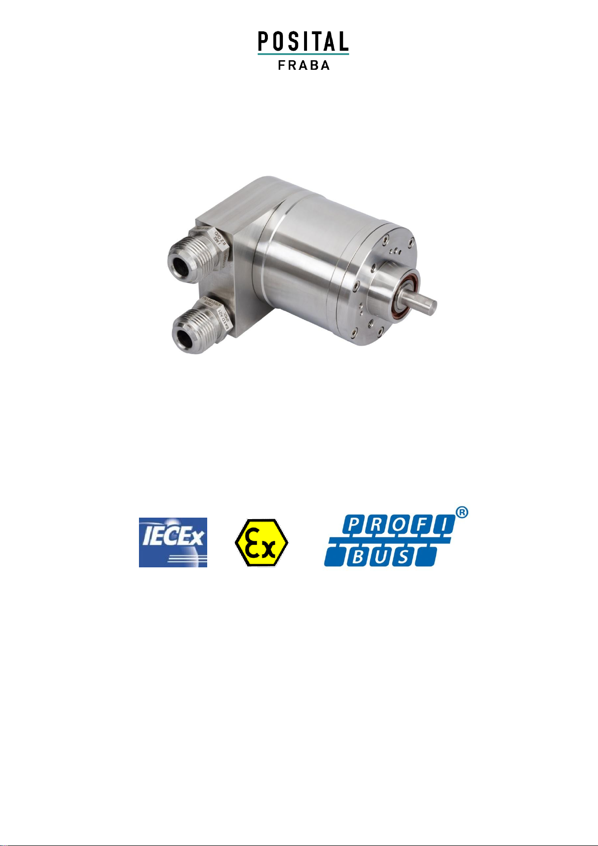
ABSOLUTE ROTARY ENCODER
IXARC EXPLOSION PROOF PROFIBUS-DP
Page 2 Info Ex OCM/OCE Revision 26.05.2014
1General............................................................4
1.1 Absolute Rotary Encoder...............................4
1.2 Profibus technology.......................................4
2Installation ......................................................5
2.1 Settings in the connection cap.......................5
2.1.1 Station address .......................................5
2.1.2 Bus termination .......................................5
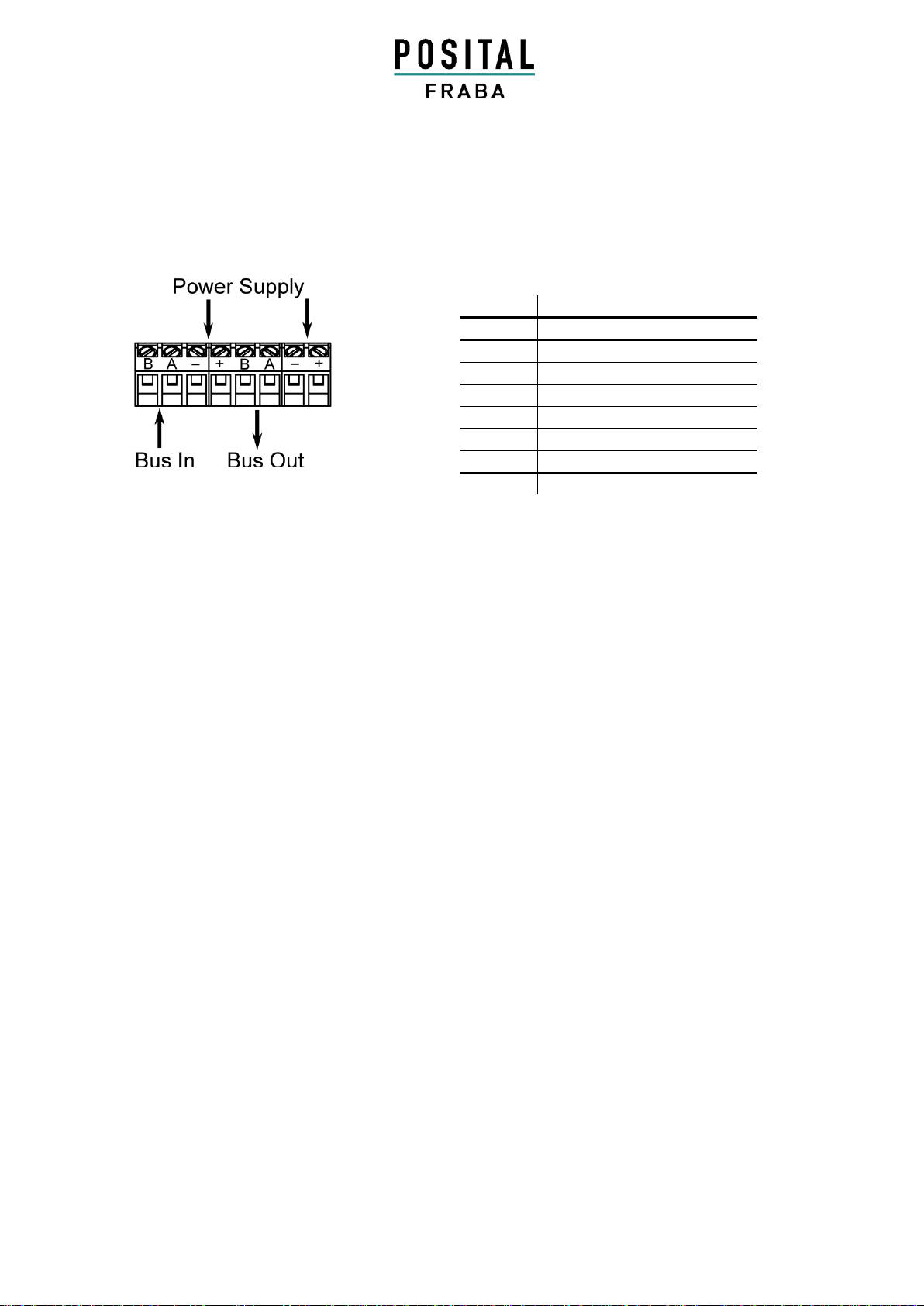
2.2 Connecting bus lines and power supply ........6
2.3 Connecting-up the connection cap with cable
glands..................................................................7
Use only EX d certified cable glands (or blind
plugs, if no cable is attached) which meet
EN/IEC 60079-1 requirements for attaching
cable to the encoder. Cable entry threads are
M20 x 1,5...............................................................7
Connecting the screen.........................................7
2.4 Instructions for mechanical installation and
electrical connection of the angular encoder .......7
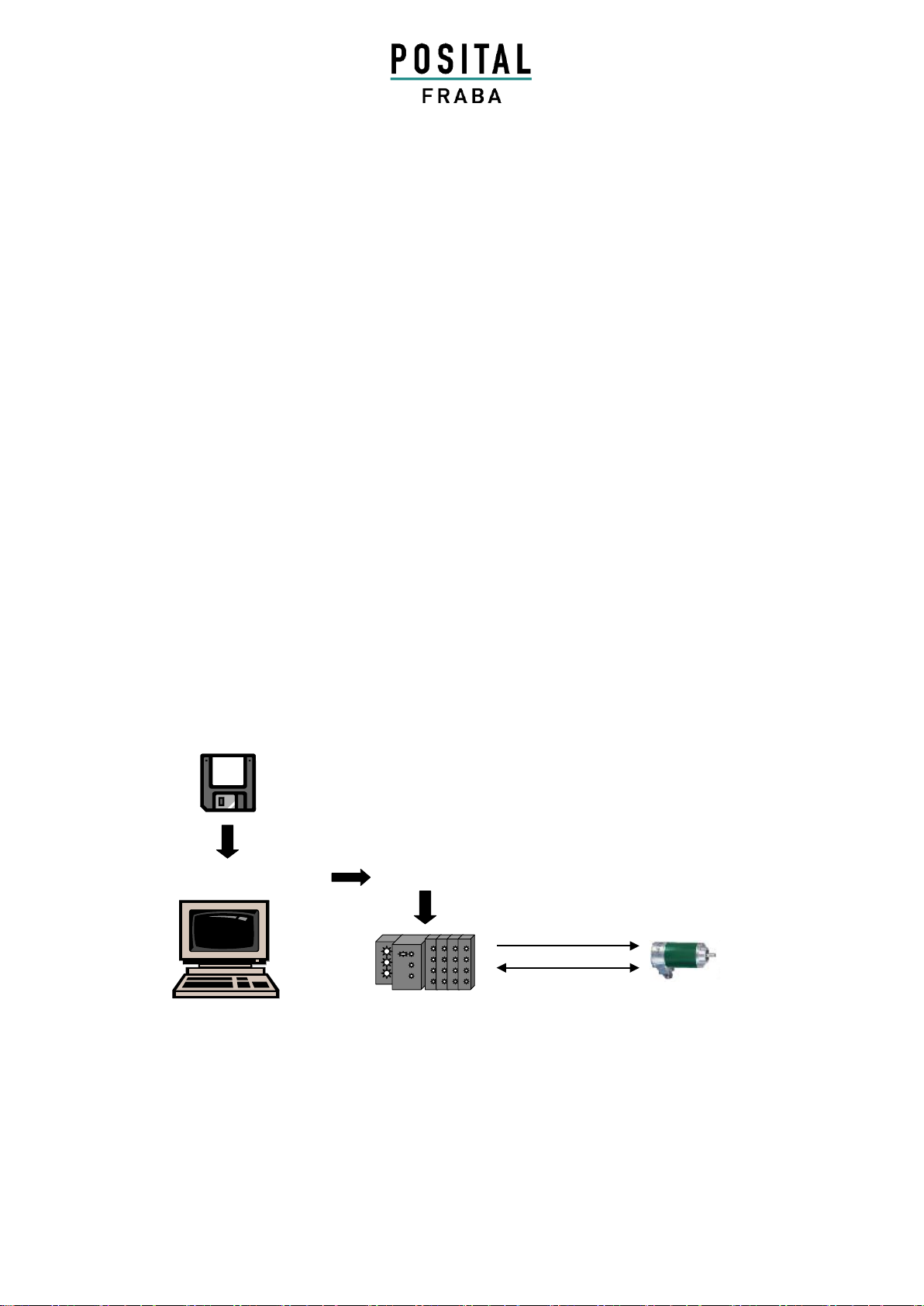
3Device Configuration.....................................9
3.1 Overview –Configuration principle................9
3.2 Overview encoder configurations -
functionality........................................................10
3.3 Encoder configurations - data format...........11
4Class 1 and Class 2 profile..........................12
4.1 Parameter settings.......................................12
4.1.1 Code sequence.....................................13
4.1.2 Class 2 functionality ..............................13
4.1.3 Commissioning diagnostics...................13
4.1.4 Scaling function.....................................13
4.1.5 Measuring units per revolution ..............13
4.1.6 Total measuring range ..........................14
4.2 Data exchange in normal operation.............15
4.2.1 Transferring the process value..............15
4.2.2 Preset function ......................................15
5Special versions FRABA 2.1 and 2.2 ..........17
5.1 Parameter....................................................18
5.1.1 Activate manufacturer-specific
parameters .....................................................18
5.1.2 Desired measuring units........................18
5.1.3 Desired Measuring units reference........19
5.1.4 Activate commissioning mode ...............20
5.1.5 Shorter Diagnostics ...............................20
5.1.6 Software-limit switch..............................20
5.1.7 Physical impulses..................................21
5.1.8 Encoder type .........................................22
5.1.9 Velocity time base..................................22
5.2 Data exchange in normal operation .............23
5.3 Commissioning mode...................................24
5.3.1 Setting the counting direction ................24
5.3.2 Teach-In Start........................................25
5.3.3 Teach-In Stop........................................25
5.3.4 Preset value...........................................26
6Diagnostic messages...................................27
6.1 Overview......................................................27
6.2 Supported diagnostic messages..................28
6.2.1 Extended diagnostics header ................28
6.2.2 Memory error.........................................28
6.2.3 Operating status ....................................28
6.2.4 Encoder type .........................................28
6.2.5 Singleturn resolution..............................28
6.2.6 Number of revolutions............................28
6.2.7 Operating time warning..........................28
6.2.8 Profile version........................................28
6.2.9 Software version....................................28
6.2.10 Operating time.....................................28
6.2.11 Zero offset ...........................................29
6.2.12 Programmed resolution .......................29
6.2.13 Programmed total resolution................29
6.2.14 Serial number......................................29
7Configuring with STEP 7..............................30
7.1 Installing the GSD file...................................30
7.2 Configuring the encoder...............................31
7.3 Selecting the encoder version......................32
7.4 Setting the parameters.................................33
7.5 Further encoder configurations....................37