INSTALLATION GUIDE
POSITAL GmbH
Carlswerkstr. 13c, D-51063 Cologne, P.O. Box 80 03 09, D-51003 Cologne
Phone +49 (0) 221-96213-0, Fax +49 (0) 221-96213-20, www.posital.com, info@posital.com
Installation of the encoder must be completed by a skilled technician or engineer. Failure to comply
with the instructions below will render the ATEX/IECEx certifications INVALID. The encoder may not
be modified by the customer.
1. Insure that power is off.
2. Connect to earth prior to proceeding. Observe precautions for handling ESD (Electro Static
Discharge) sensitive devices.
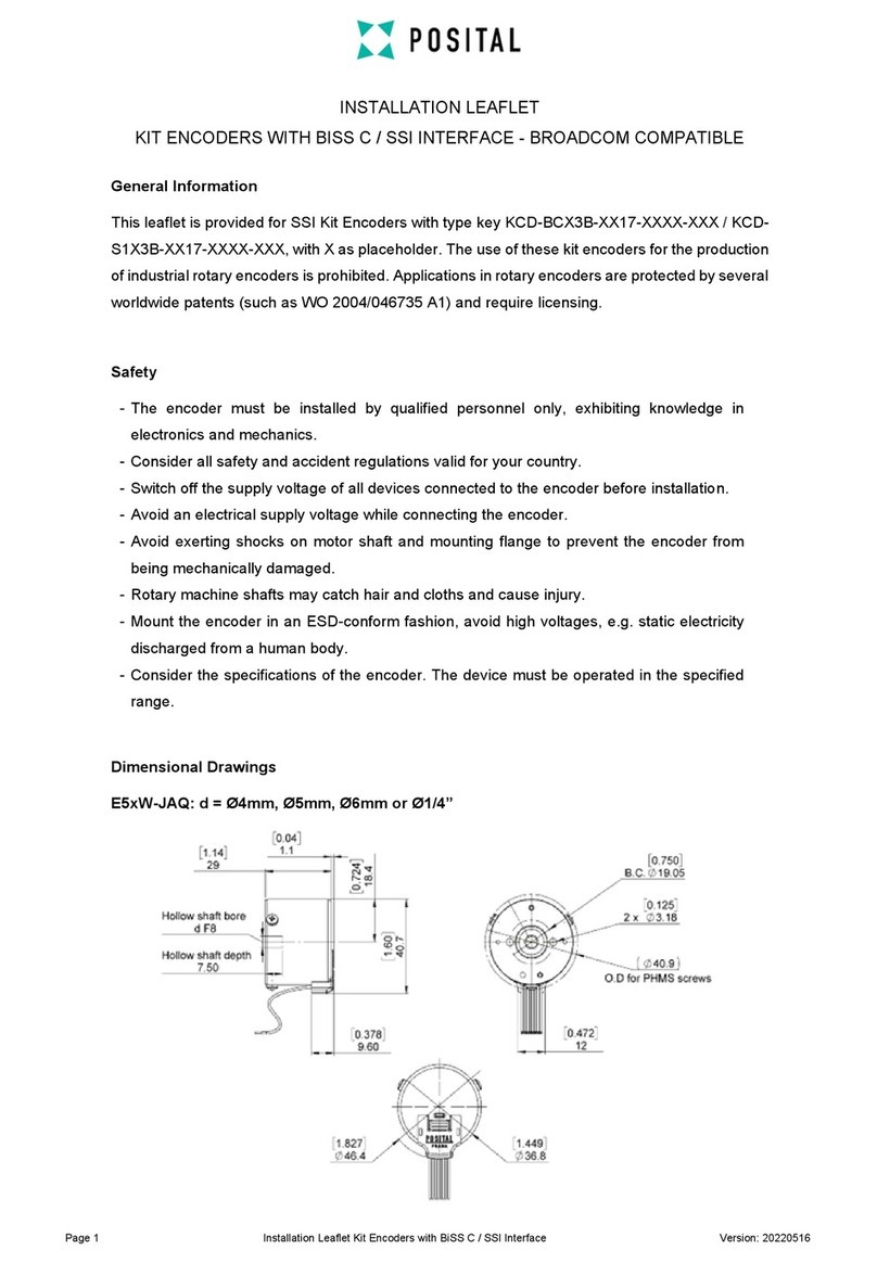
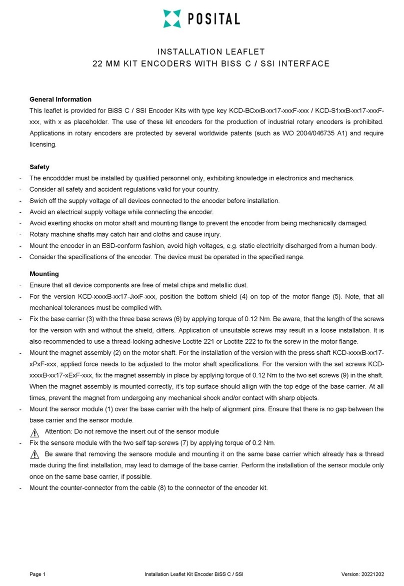
3. When mounting the Solid Shaft encoder, use either M3, M4, or M6 screws.
4. When installing the Blind Hollow Shaft encoder, check that the encoder fixing
clamp is loose.
5. Slide encoder hollow bore over motor shaft (or other device).
6. Align encoder spring coupling or torque arm mounting hole(s) with motor face
plate hole(s). Insert screws into mounting holes and tighten.
7. Tighten fixing clamp M3 screw (maximum 1.5 Nm (1.12 lbft) torque).
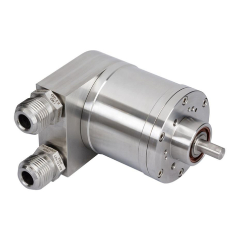
8. Use only EX d certified cable glands (or blind plugs, if no cable is attached) which meet EN/IEC
60079-1 requirements for attaching cable to the encoder. Cable entry threads are M20 x 1,5.
9. Use only shielded cable. Be aware of National Wiring Standards for ATEX environments. For
ambient temperatures below -10o C and above +60o C use field wiring suitable for minimum and
maximum ambient temperatures.
10. Connect encoder Circuit Ground (GND).
11. Connect remaining Output wires to PLC. Then apply power (insure the Supply Voltage is
correct!).
12. If used, safety screws in the cap shall have a minimum yield stress of 450 MPa, class A2-70 or A4-
70.
13. Precautions must be taken to avoid dust from forming layers on the encoder.
14. It is strongly recommended that the original packaging be used for any additional shipping or
transport.


