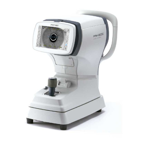
Potec PDR-7000 User manual

OPERATION MANUAL
DIGITAL REFRACTOR PDR-7000
Revision 0.5 www.potec. iz
Before using the instrument, be sure to read this manual thoroughly.

PDR-7000 Operation Manual
- i -

PDR-7000 Operation Manual
IMPORTANT NOTICE
This roduct may malfunction due to electromagnetic waves caused by ortable ersonal
tele hones, transceivers, radio-controlled toys, etc. Be sure to avoid having objects such
as, which affect this roduct, brought near the roduct.
The information in this ublication has been carefully checked and is believed to be
entirely accurate at the time of ublication. POTEC assumes no res onsibility, however, for
ossible errors or omissions, or for any consequences resulting from the use of the
information contained herein.
POTEC reserves the right to make changes in its roducts or roduct s ecifications at any
time and without rior notice, and is not required to u date this documentation to reflect
such changes.
© 2018 POTEC Co., Ltd.
40-4, Techno 2-ro, Yuseong-gu, Daejeon, 34015, Korea
All rights reserved.
Under copyright l ws, this m nu l m y not be copied, in whole or in p rt, without the prior written consent of
POTEC.
- ii -

PDR-7000 Operation Manual
SAFETY INFORMATION
Accessory equi ment connected to the analog and digital interfaces must be certificated
according to the res ective IEC standards (e.g. IEC 60950-1 for data rocessing
equi ment and IEC 60601-1 for medical equi ment). Furthermore all configurations shall
com ly with the system standard EN 60601-1:2006, Clause 16. Everybody who connects
additional equi ment to the signal in ut art or signal out ut art configures a medical
system, and is therefore res onsible that the system com lies with the requirements of the
system standard IEC 601-1-1. If in doubt, consult the technical service de artment or your
local re resentative.
For U.S.A
Do not make any changes or modifications to the equi ment unless otherwise s ecified in
the manual.
If such changes or modifications should be made, you could be required to sto o eration
of the equi ment.
For EU Countries
The following mark, the name & address of the EU Re resentative shows com liance of
the instrument with Directive 93/42/EEC.
Authorized Representative:
Medical Device Safety Service Gm H
Schiffgraben 41, D-30175
Hannover, Germany
- iii -

PDR-7000 Operation Manual
Symbols marked on the Instrument
Symbol Descri tion
Protective earth (ground)
Refer to o erating instructions
OOff ( ower: disconnect to the mains)
IOn ( ower: connection to the mains)
I
Dis osal of your old a liance
When this crossed-out wheeled bin symbol is attached to a
roduct it means the roduct is covered by the Euro ean
Directive 2002/96/EC.
All electrical and electronic roducts should be dis osed of
se arately from the munici al waste stream via designated
collection facilities a ointed by the government or the local
authorities.
The correct dis osal of your old a liance will hel revent
otential negative consequences for the environment and
human health.
For more detailed information about dis osal of your old
a liance, lease contact your city office, waste dis osal
service or the sho where you urchased the roduct
General Safety Information
If you see any warnings or cautions rinted on the warning labels, follow the safety
instructions in this manual. Ignoring such cautions or warnings while handling the roduct
may result in injury or accident. Be sure to read and fully understand the manual before
using this roduct.
Kee this manual in easy-to-access lace.
Caution Sign Descri tion
This indicates a otentially hazardous situation which could results
in death or serious injury to you or others.
This indicates hazardous situations which may result in minor injury
to you or others, or may result in machine damage.
This is used to em hasize essential information. Be sure to read
this information to avoid incorrect o eration.
- iv -
CAUTION
WARNING
NOTE

PDR-7000 Operation Manual
WARNING
To avoid the risk of electric shock, this equi ment must only be
connected to a su ly mains with rotective earth.
WARNING
Only o erate the instrument with the ower su ly indicated on the
rating late. Otherwise, it may result in fire or electric shock.
WARNING
Be sure to turn OFF the ower switch before connecting or
disconnecting the cables. Also, do not handle them with wet hands.
Otherwise, you may get an electric shock that may result in death
or serious injury.
WARNING
Never disassemble or modify this instrument because it may result
in fire or electric shock. Also, since this instrument incor orates
high-voltage arts and other hazardous arts, touching them may
cause death or serious injury.
WARNING
Should any of the following occur, immediately turn OFF the ower
switch, un lug the ower cable from the AC outlet, and contact the
dealer or the agent who/where you urchase this instrument.
When there is smoke, strange odor or abnormal sound.
When liquid has been s illed into the instrument or a metal
object has entered through an o ening.
When the roduct has been dro ed or its housing damaged.
CAUTION
This instrument is shi ed with a grounding ty e ower cable. To
reduce the risk of electric shock, always lug the cable into a
grounded ower outlet.
CAUTION
Wi e the forehead rest with ethanol or glutaraldehyde solution to
disinfect it each time a different examinee uses it, in order to
revent infection.
CAUTION
Do not use the device near, on, or under other electronic equi ment
to avoid electromagnetic interference with the o eration of the
device.
CAUTION
Do not use the device in the same room with other equi ment such
as life-su ort equi ment, other equi ment that has major affects
on the life of atient an results of treatment , or other measurement
or treatment equi ment that involve small electric current.
CAUTION
Do not use the device simultaneously with ortable and mobile
radio frequency communication systems because it may have an
adverse effect on o eration of the device.
CAUTION
Do not use cables and accessories that are not s ecified for the
device because that may increase the emission of electromagnetic
waves from the device or the system and decrease the immunity of
the device to electromagnetic disturbance.
CAUTION
Do not lace the multi le socket-outlet for PDR-7000 system on the
floor in order to revent liquid enetration and damage to the
roduct.
CAUTION
PDR-7000 system shall not be connected with additional multi le
socket-outlets or extension cords in addition to a designated single
multi le socket-outlet.
CAUTION
Maximum ermissible load of each socket-outlet used for the PDR-
7000 system, shall not be less than 100VA.
- v -

PDR-7000 Operation Manual
CAUTION
If non-medical electrical equi ments (e.g. Video monitor, IT
equi ment, etc.) that are connected with the PDR-7000 are, directly
connected to the wall socket-outlets, high touch current may flow
since the earth continuity is not ensured.
CAUTION
Multi le socket-outlet should be a grounding-ty e and com lied
with IEC 60884-1.
CAUTION
Connection of the lug shall be ossible only by using the tool.
(Refer to the figure below.)
- vi -

PDR-7000 Operation Manual
CONTENTS
IMPORTANT NOTICE----------------------------------------------------------------------II
SAFETY INFORMATION------------------------------------------------------------------III
CONTENTS----------------------------------------------------------------------------------VII
1 BEFORE USE-----------------------------------------------------------------------------1
1.1 Outline of the Refractor-----------------------------------------------------------------------------------------------------1
1.2 Intended Use--------------------------------------------------------------------------------------------------------------------1
1.3 Configuration-------------------------------------------------------------------------------------------------------------------2
1.3.1 Refractor head-----------------------------------------------------------------------------------------------------------2
1.3.2 Control ox(CB)---------------------------------------------------------------------------------------------------------4
1.3.3 Junction ox (JB)------------------------------------------------------------------------------------------------------11
1.4 La els----------------------------------------------------------------------------------------------------------------------------12
1.5 Before First Use--------------------------------------------------------------------------------------------------------------13
1.6 Getting Started and Exiting----------------------------------------------------------------------------------------------14
1.6.1 Getting started----------------------------------------------------------------------------------------------------------14
1.6.2 Restore from power saving mode-------------------------------------------------------------------------------14
1.6.3 Exiting---------------------------------------------------------------------------------------------------------------------14
2 OPERATING PROCEDURES-------------------------------------------------------15
2.1 Operation Flow---------------------------------------------------------------------------------------------------------------15
2.2 Entering Data------------------------------------------------------------------------------------------------------------------16
2.2.1 From an auto Ref/Keractometer----------------------------------------------------------------------------------16
2.2.2 From a lensmeter------------------------------------------------------------------------------------------------------17
2.2.3 From a PC----------------------------------------------------------------------------------------------------------------18
2.2.4 Manual data entry with the dial-----------------------------------------------------------------------------------21
2.3 Setting Prism------------------------------------------------------------------------------------------------------------------22
2.3.1 Switching etween rectangular and polar coordinates--------------------------------------------------22
2.3.2 Rectangular coordinates (XY)-------------------------------------------------------------------------------------22
2.3.3 Polar coordinates (rθ)------------------------------------------------------------------------------------------------23
2.3.4 Removing rotary prism lenses------------------------------------------------------------------------------------23
2.3.5 Prism data clear--------------------------------------------------------------------------------------------------------23
2.4 Preparation--------------------------------------------------------------------------------------------------------------------24
2.5 Standard Program Refraction-------------------------------------------------------------------------------------------25
2.5.1 Fixed Program A-------------------------------------------------------------------------------------------------------25
2.6 Chart Presentation----------------------------------------------------------------------------------------------------------32
2.6.1 Chart selection---------------------------------------------------------------------------------------------------------32
2.6.2 Visual acuity chart mask functions-----------------------------------------------------------------------------32
- vii -

PDR-7000 Operation Manual
2.6.3 Random chart function----------------------------------------------------------------------------------------------34
2.7 Printing--------------------------------------------------------------------------------------------------------------------------34
3 ADVANCED FEATURES-------------------------------------------------------------35
3.1 Vision Test Screens Presented to Patient--------------------------------------------------------------------------36
3.2 Data List------------------------------------------------------------------------------------------------------------------------38
3.3 Setting for connection with Chart projectors----------------------------------------------------------------------39
3.4 Setting Auxiliary Lenses--------------------------------------------------------------------------------------------------40
3.5 Fog Function for testing a single eye--------------------------------------------------------------------------------41
3.6 Fog Function for testing oth eyes-----------------------------------------------------------------------------------42
3.7 Calling Up Measurement Data.------------------------------------------------------------------------------------------43
3.8 Link Off Function------------------------------------------------------------------------------------------------------------43
3.9 Programming------------------------------------------------------------------------------------------------------------------43
3.9.1 Programming------------------------------------------------------------------------------------------------------------44
3.9.2 Operating programs--------------------------------------------------------------------------------------------------45
3.10 Entering Comments--------------------------------------------------------------------------------------------------------46
3.11 Setting Time and Date-----------------------------------------------------------------------------------------------------47
3.12 Touch-screen Panel Cali ration----------------------------------------------------------------------------------------48
3.13 Parameter Settings----------------------------------------------------------------------------------------------------------49
4 TEST METHOD-------------------------------------------------------------------------55
4.1 Unaided Visual Acuity Test----------------------------------------------------------------------------------------------55
4.2 Aided Visual Acuity Test--------------------------------------------------------------------------------------------------55
4.3 Astigmatism Test------------------------------------------------------------------------------------------------------------56
4.3.1 Astigmatism test with astigmatism clock dial---------------------------------------------------------------56
4.3.2 Astigmatism test with cross cylinder lens--------------------------------------------------------------------57
4.4 Spherical Refinement------------------------------------------------------------------------------------------------------58
4.4.1 Red-green test----------------------------------------------------------------------------------------------------------58
4.4.2 Cross grid test for far vision---------------------------------------------------------------------------------------59
4.5 Binocular Visual Function Test-----------------------------------------------------------------------------------------60
4.5.1 Binocular alance test-----------------------------------------------------------------------------------------------60
4.5.2 Polarized red-green test---------------------------------------------------------------------------------------------61
4.5.3 Phoria test----------------------------------------------------------------------------------------------------------------62
4.5.4 Phoria with fixation test---------------------------------------------------------------------------------------------64
4.5.5 Von Graefe test (horizontal phoria)-----------------------------------------------------------------------------66
4.5.6 Von Graefe test (vertical phoria)---------------------------------------------------------------------------------67
4.5.7 Vertical coincidence test--------------------------------------------------------------------------------------------68
4.5.8 Horizontal coincidence test----------------------------------------------------------------------------------------70
4.5.9 Scho er test-------------------------------------------------------------------------------------------------------------72
4.5.10 Stereo test----------------------------------------------------------------------------------------------------------------74
- viii -

PDR-7000 Operation Manual
4.5.11 Worth test----------------------------------------------------------------------------------------------------------------75
4.5.12 Maddox test (horizontal phoria)----------------------------------------------------------------------------------76
4.5.13 Maddox test (vertical phoria)--------------------------------------------------------------------------------------77
4.6 Near Addition Test with Fused Cross Cylinder Lenses--------------------------------------------------------78
4.7 Negative Relative Accommodation Test-----------------------------------------------------------------------------79
4.8 Positive Relative Accommodation Test------------------------------------------------------------------------------80
4.9 Negative Relative Convergence Test---------------------------------------------------------------------------------81
4.10 Positive Relative Convergence Test----------------------------------------------------------------------------------82
5 MAINTENANCE------------------------------------------------------------------------83
5.1 Trou leshooting-------------------------------------------------------------------------------------------------------------83
5.2 Replacing Fuses-------------------------------------------------------------------------------------------------------------83
5.3 Replacing printing paper--------------------------------------------------------------------------------------------------84
5.4 Cleaning Measuring Windows------------------------------------------------------------------------------------------85
5.5 Cleaning Exterior------------------------------------------------------------------------------------------------------------85
5.6 Service Information---------------------------------------------------------------------------------------------------------85
6 TECHNICAL INFORMATIONS-----------------------------------------------------86
6.1 Classifications----------------------------------------------------------------------------------------------------------------86
6.2 Specifications-----------------------------------------------------------------------------------------------------------------87
6.3 Components-------------------------------------------------------------------------------------------------------------------88
7 APPENDIX-------------------------------------------------------------------------------89
7.1 Linkage etween Charts and Auxiliary Lenses-------------------------------------------------------------------89
7.2 VA Conversion Ta le-------------------------------------------------------------------------------------------------------90
7.3 Preset Addition Power-----------------------------------------------------------------------------------------------------90
7.4 Estimated Visual Acuity Ta le------------------------------------------------------------------------------------------91
7.5 Standard Programs---------------------------------------------------------------------------------------------------------92
7.6 Guidance for connection of PDR-7000 with other devices----------------------------------------------------94
7.6.1 How to import data from CANON R/K to PDR-7000-------------------------------------------------------95
7.6.2 How to import data from NIDEK and TOPCON R/K to PDR-7000-------------------------------------96
7.6.3 Connectors--------------------------------------------------------------------------------------------------------------98
7.6.4 Setting for connection with the external instrument------------------------------------------------------99
- ix -

PDR-7000 Operation Manual
1 BEFORE USE
1.1 Outline of the Refractor
The POTEC REFRACTOR Model PDR-7000 is a com uterized refractor used for
subjective refraction with the connected POTEC AUTO REF/KERATOMETER,
LENSMETER, CHART PROJECTOR1.
The PDR-7000 includes a refractor head, control box, junction box.
The control box includes the key anel and dis lay. The dis lay is touch-screen anel.
The control box allows the data to be dis layed and almost all o erations to be
erformed. In addition, the control box o erates the refractor head and also connected
chart resenting device. It allows the refractor and charts to be controlled together.
1.2 Intended Use
Instrument roviding means of ositioning s herical and cylindrical lenses, risms and
other o tical devices in front of a subject's eyes for ur ose of determining refractive
error and binocular functions. This roduct(PDR-7000) is used for detecting and
measuring any anomalies in binocular vision such as muscle balance, binocular
balance, aniseikonia, fusion, and stereo sis. This roduct is for medical use which
must be used under instructions of an eye care rofessional or a doctor.
No contraindication.
In this o erator's manual, the keys on the control box are indicated by key re resenta-
tions like or
The touch buttons on the touch anel other than chart buttons are indicated by
brackets like [LAMP].
The touch anel chart buttons are indicated by button re resentations like
1 Connectable instruments: PRK-5000, PRK-5000L, PRK-6000, PRK-7000, PRK-8000, PLM-6100, PLM-8000,
PACP-7000, PACP-7000L, PLC-7000, PLC-7000 ola, PLC-7100, PLC-7100 ola, PLC-8000, PLC-8000 ola
- 1 -

PDR-7000 Operation Manual
1.3 Configuration
1.3.1 Refractor head
1. Measuring window
3. VD check window
2. Near point lamp
4. Forehead rest detection lamp
5. Forehead rest knob
. Level
7. Near point card
8. Near point rod
9. Level adjustment knob
Operator’s side
Patient’s side
10. Forehead rest
11. Face shield
- 2 -

PDR-7000 Operation Manual
1.Measuring window
The atient looks at any chart through these windows.
2.Near oint lam
Illuminates the near oint card.
The lam lights u or goes out by ressing the ON/OFF button in ‘Near chart lam
control’ of [LAMP] o -u on the right-u window.
3.VD check window
Used to check the atient’s VD(vertex distance : distance from the corneal a ex to the
lens). The windows have calibration markings of 12, 13.5, 16, 18, and 20mm.
4.Forehead rest detection lam
Used to confirm that the atient’s forehead contacts the forehead rest.
When the forehead contacts the forehead rest, the lam lights out.
5.Forehead rest knob
Moves the forehead rest forward and backward in order to adjust the VD.
6.Level
Used to confirm that the refractor head is level.
Turn the level adjustment knob until the air bubble is centered in the level.
7.Near oint card
Used for near vision test such as addition owers.
When the chart is shifted to the left slightly, the chart
ex lanation is indicated.
Chart explanation
8.Near oint rod
The distance from the atient’s eye to the near
oint card is marked in inches and centimeters.
Align the black line at the near oint card holder
with the scale of a desired distance.
The number in red re resents the ower(dio ter)
corres onding to each distance in meters.
9.Level adjustment knob
Adjusts the level of the refractor head.
The refractor head is tilted by 2.5 at maximum to the left or right.
10.Forehead rest
The atient’s forehead touches here during refraction. Clean it before ach refraction.
11.Face shield
The atient’s face touches here during refraction. Clean the face shields before each
refraction.
NOTE The materials com osed of the arts that contact the atient during refraction are as
- 3 -

PDR-7000 Operation Manual
follows.
- Forehead rest: oly ro ylene, Face shields: ABS resin
1.3.2 Control ox(CB)
1. USB slot
2. Control panel
. Printer
3. Dial
3. Dial switch
5. Display
1.USB Slot
Used to u grade CB software.
2.Control anel
See “Control anel”( age 8) for details.
3. Dial
Changes any measurement value.
The selected(highlightened) value can be changed
Turn it clockwise The value changes to the negative.
Turn it counterclockwise The value changes to the ositive.
Turn the dial while ressing changes the increment. See age 51.
4. Dial switch
Switches the mode (S, C, A, VA).
The values of S, C, A, and/or VA selected or selection order varies de ending on
the Dial switch arameter setting.
5. Dis lay
Dis lays the data such as SPH(S), CYL(C), AXIS(A) and the resented chart.
The LCD dis lay is a touch-screen anel.
6. Print
Used for rinting data.
- 4 -

PDR-7000 Operation Manual
○ Display
Date Measurement
Mode
Auxlliary
lenses PD
Far or Near
mode button
Touch holding
button
Lamp on off button
Setting button
Operation message
Present chart
Next chart
Present program
Chart buttons
Function buttons
Previous Mode
and data
Mode and data
prior to previous
○ Control panel
7- 5
1
7- 1 7- 2 7- 3 7- 4 7- 7 7- 8 9 10
11- 4
11- 3
11- 1
11- 2
6
7- 6
1- 1
1- 2
1- 4
1- 5
4
1- 3
2
3 5 13- 1 14- 1 8- 1 8- 2 8- 3 14- 2 13- 2 12- 1 12- 2
- 5 -

PDR-7000 Operation Manual
1. Data keys
Used to enter the data into the PDR-7000 and measure each data.
The selected data is dis layed at the center of the screen. Which key is selected is
dis layed in the u er-left corner of the screen. ressing the em ty data key co ies
the reviously dis layed data into that field.
See “2.2 Entering Data” for data entry method.
1-1.
Measures the unaided visual acuity.
The corrective lens ower in the refractor head is 0 D.
1- 2.
Enter the lensmeter(LM) data.
1- 3.
Enters the data from an auto Ref/Keratometer
1- 4.
Used to obtain the full correction.
When the data is received from an auto Ref/Keratometer or a lensmeter, this field o ens
automatically.
The ela sed time from data entry is dis layed in the subjective data field when the
O erating timer arameter is set to Yes.
1- 5.
Used to obtain the final rescri tion and best-corrected visual acuity.
Pressing this key co ies the full correction data from the subjective data field and adjusts it
to the final rescri tion.
2.
The increment or mode changes when a key is ressed or the dial is turned with this
key.
3.
Prints the data or ex orts it to an external com uter.
See “2.7 Printing”
4.
Enters the data from an auto refractometer or lensmeter.
Press this key and confirm that the data No. on the screen are the same with the oint
data No. of the auto Ref/Keratometer or lensmeter. S ecify the field that the data is
entered with the data key like ,
5.
Switches the measuring windows to be o ened or occluded.
6.
Indicates the ex lanation about the resent chart.
Press this key again or [X] button to cancel the indication.
When this key is ressed during the standard rogram or rogram with sam le
instruction, the sam le instructions for the test a ear.
- 6 -

PDR-7000 Operation Manual
7. Mode Keys
Select the mode whose data is changed.
Pressing any keys highlights the corres onding field to be changed.
The value in each mode can be changed with the dial or
7-1.
Goes into SPH mode which allows s herical owers to be adjusted.
7-2.
Goes into CYL mode which allows cylindrical owers to be adjusted.
7- 3.
Goes into AXIS mode which allows cylindrical axis to be adjusted.
7- 4.
Goes into ADD mode which allows addition owers to be adjusted.
The refractor head converges to the working distance of 40cm (variable) automatically
in near mode.2
See the Working Distance.(WD) arameter(3.12 Parameter Settings).
- When the Preset ADD arameter is set to Yes, the atient’s age can be selected.
- Each time the key is ressed while the refractor head converges, the addition owers are added or
removed.
When the addition owers are removed, the highlight color for ADD on the screen changes
and the time dis lay switches owers are added.
After addition ower entry, the WD dis lay a ears to select a desired WD with the
function button.
7-5.
Goes into the mode which allows the visual acuity to be entered with the dial.
7- 6.
Goes into the mode which allows the PD in the refractor head to be adjusted.
Monocular PD(1/2 PD) Adjust the PD after ressing or in
PD mode.
To exit from the mode Press again or mode button(S,C,A, …)
7-7.
Goes into the mode which allows base in/out rism ower in rectangular
coordinates or rism absolute value in olar coordinates to be entered.
See “2.3 Setting Prism”.
7-8.
Goes into the mode which allows base u /down rism ower in rectangular
coordinates or rism base angle in olar coordinates to be entered.
2 The addition owers are reset according to the selected age. See “7.3 Preset Addition Power”.
- 7 -

PDR-7000 Operation Manual
8. Eye selection keys
Select the right eye (R), left eye (L), or both eyes (BIN) for subjective refinement.
- The occluder is laced automatically in the non-selected eye side.
- However, it is not laced during the binocular vision test with olarizing.
8-1.
O ens the right measuring window and laces the occluder in the left one.
When the binocular vision test chart is selected, the left eye side is not occluded but
the data entry only for the right eye is also ossible.
8-2.
O ens the left measuring window and laces the occluder in the right one.
When the binocular vision test chart is selected, the left eye side is not occluded but
the data entry only for the right eye is also ossible.
8- 3.
O ens the both measuring windows.
The data entry for both eyes are available.
9.
Dis lays the Main Menu screen.
10.
Clears all dis layed data.(Initializes the CB(Control box) data).
- + : Initializes the CB with aligning refractor head
11. Mask keys
Isolate any horizontal or vertical line or single letter on the chart. Press any of the chart
keys to cancel the mask functions. the visual acuity of the isolated horizontal line or
letter is shown in the VA field on the screen.
11- 1.
Isolates a horizontal line (same visual acuity letters) on the to or bottom line of the VA
chart.
- This key also moves the isolation u and down when the horizontal line has been isolated.
- + : Isolates the horizontal line on the to line of the chart.
- + : Isolates the horizontal line on the bottom line of the chart.
11- 2.
Isolates a vertical line on the VA chart.
- This key also moves the isolation to the left or right when the vertical line or single letter has been
isolated.
- + or : Isolates a single letter in the lower-left or right corner on the chart.
11- 3.
Isolates a single letter on the VA chart.
The letter in the u er-right corner of the chart is isolated.
- + : Isolates a single letter in the u er-left corner on the chart.
- 8 -

PDR-7000 Operation Manual
11- 4.
Isolates a horizontal line in the middle of the VA chart.
- + : A lies the red-green filter on the VA chart.
- + again : Releases the red-green filter.
12. Program keys
See “2.5 Standard Program Refraction” for rogrammed refraction.
12- 1.
Starts a rogram.
- Pressing this key again restarts the rogram.
- + : Switches the rogram between FixA, B and userA~H.
12- 2.
Used to forward next rogrammed refraction sequence.
- + : Returns to the revious sequence.
13. Cross cylinder keys
Place a cross cylinder lens to measure the cylindrical axis or ower. when the key is
ressed with both eyes o en, the left measuring window is occluded automatically.
O en the left measuring window with to erform the astigmatism test with both
eyes o en.
It is ossible to select the cross cylinder lens to be inserted with the Cross cylinder
(XC) test arameter.
When the arameter is set to ±0.25 or ±0.50, the cross cylinder lens is inserted as
follows.
13- 1.
In the cylindrical axis measurement, the cross cylinder lens is inserted so that the
minus axis is located at 45° from the minus axis osition of the cylindrical lens.
In the cylindrical ower measurement, the cross cylinder lens is inserted so that the
minus axis is located at 90° from the minus axis osition of the cylindrical lens.
Clears the rism data for the right eye in rism entry mode.
13- 2.
In the cylindrical axis measurement, the cross cylinder lens is inserted so that the
minus axis is located at 135° from the minus axis osition of the cylindrical lens.
In the cylindrical ower measurement, the cross cylinder lens is inserted so that the
minus axis is located at 0° from the minus axis osition of the cylindrical lens.
14. Value change keys
Functions as the same as the dial.
14-1.
Increases the value to the ositive side in increments of one.
14- 2.
Decreases the value to the negative side in increments of one.
- 9 -

PDR-7000 Operation Manual
○ Bottom of the control ox
1. CMOS BATTERY COVE R
1. CMOS BATTERY COVER
Used for changing CMOS BATTERY.
- 10 -
Table of contents
Other Potec Medical Equipment manuals