7
Technical Support: +44(0)23 9269 6638 (option 3) PAK200788_02A July 2019 ©2019 ELMDENE INTERNATIONAL LTD
CAUTION – DO NOT CONNECT the two remaining (free) battery terminals to each other
27. Using the battery lead provided, connect the two white wires to the “Temp” terminals on the PSU
(polarity is not important) and the RED lead to “Bat+” and
the BLACK lead to “Bat–“.
CAUTION: Connect battery leads to PSU terminals FIRST - THEN
connect to the battery LAST.
28. Connect the red battery lead to the free positive battery
terminal and the black battery lead to the free negative
battery terminal.
CAUTION – significant energy can be released from an SLA
battery. When connecting the last battery lead, take extreme
care to attach the cable ONLY to the correct terminal. Avoid
shorting it to any other terminal or conducting surface.
CAUTION – the supplied battery lead contains a temperature sensor – DO NOT attempt to modify this
lead in any way and do not use an alternative method of connecting the batteries.
29. Reconnect the mains supply and verify that Fault LED #3 is off and Battery LED #2 indicates flashing or
constant Green. 2402ST only accepts batteries >= 22V.
Note: Batteries as low as 19V may be connected, but this is NOT ADVISED as this could indicate damaged
batteries. To connect batteries as low as 19V, carefully disconnect one white temperature sensor wire from
the “TEMP” terminal block). This will induce a thermistor fault. Then wire the batteries to the terminals
(follow steps 27-28). Once the batteries are charging, clear the thermistor fault by reconnecting the
thermistor wire.
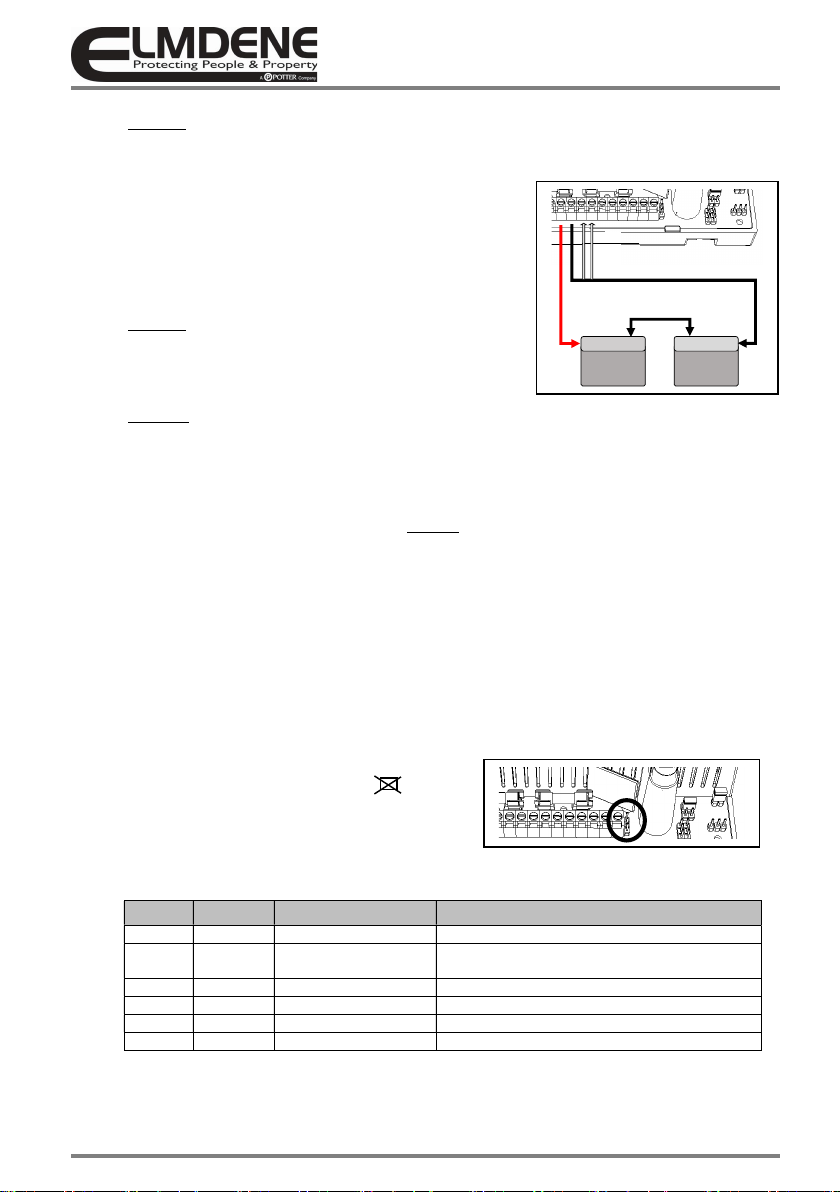
30. Verify GEN Fault relay n/c contact is closed, (com to n/c terminals = short circuit)
31. Disconnect the mains power. Verify that the green Mains LED #1 extinguishes, and the Yellow Fault LED
#3 starts to flash (indicating that the PSE is running from its standby batteries).
32. If connected, verify that the EPS Fault output shows an open contact (com and n/c terminals = open
circuit) and the GEN PSU Fault output shows a closed contact (com and n/c terminals = short circuit).
33. Verify that the standby batteries are now supporting the system load. Perform a full functional test of
system including full alarm condition Note: ensure batteries have sufficient charge to support the
system under full load.
34. To prevent battery fault indication when no battery
is required, fit the “No Battery” link ( ).
Please note; fitting of this link invalidates EN54-4,
EN12101-10 and NF S 61-940 compliance.
Final Commission
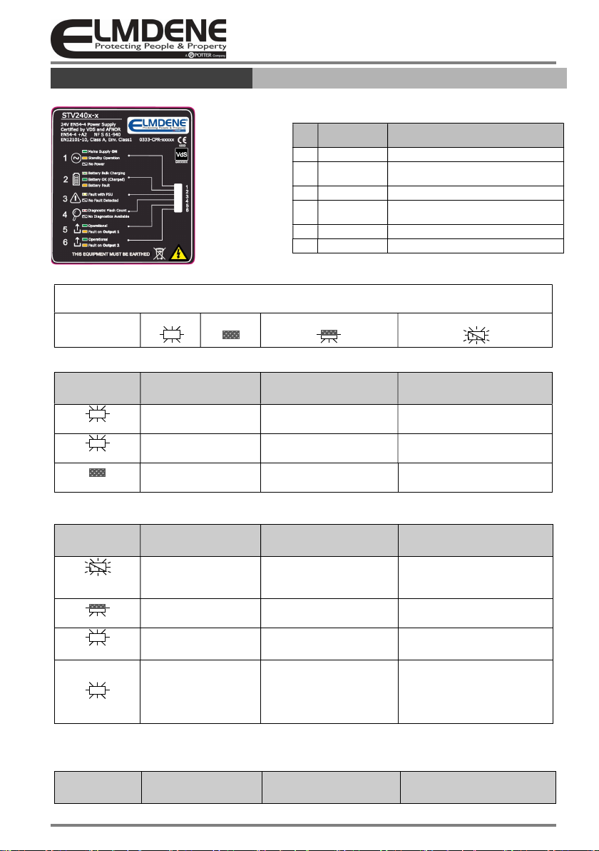
35. Reconnect the mains. Verify that
LED # Symbol LED Colour Function
1 Mains Constant Green Indication: Mains supply = OK
2 Batt Green flash x1
(repeating)
Indication: Battery Charging (bulk phase)
3 Fault OFF Indication: No Fault
4 Diagnostic OFF Indication: No Fault
5 OP1 Constant Green Indication: Output 1 = OK
6 OP2 Constant Green Indication: Output 2 = OK
(See also ‘Status and Fault-Diagnostic LED Indication‘ table for full details of LED indications.)
+ -
T T
12V
BATTERY
+ -
12V
BATTERY
+ -
FAULT OUTPUTS
TEMPER ATURE SENSOR
SERIES BATTERY LINK
+ -
T T
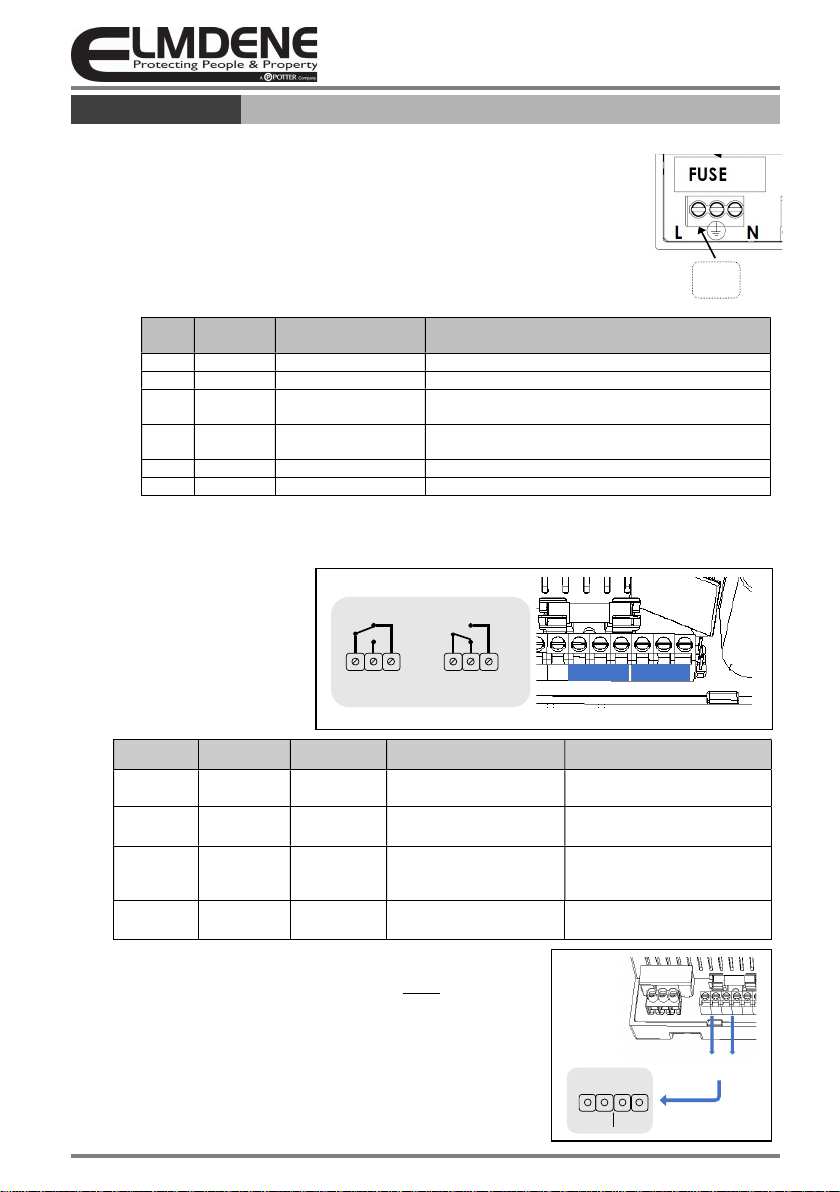
FUSE #2