Potter Elmdene STX2402-E User manual

1
Technical Support: +44(0)23 9269 6638 (option 3) PAK200582_02B August 2016 ©2016 ELMDENE INTERNATIONAL LTD
27.6 Vdc 2 Amp Switch Mode Power Supply for Fire –EN54-4:1997 +A1 +A2
STX2402-E
STX2402-C
FEATURES
The STX2402-x is an EN54-4:1997 +A1 +A2 approved power supply ideal for use in Fire and Smoke and
ventilation control Systems. Its regulated 27.6V dc output will supply up to 2 Amps continuous into
the load, in addition to providing up to 700 mA for charging the standby batteries up to 18 Ah. The
power supply output features electronic short circuit protection under both mains and standby
battery operation. Maximum battery life is assured through continuous active battery monitoring and
the use of a two stage charger, comprising bulk and temperature compensated final float phase
depending upon battery condition. Once fully charged the product operates in Eco power saving
mode, whereby the batteries are charged for 4 hours in every 24 hour period while still being
continuously monitored. This reduces wasted energy in charging already fully charged batteries and
extends their working life. Deep discharge protection prevents premature battery failure when
operating from standby for extended periods. Two sets of volt free solid state relay fault output signal
(i) loss of mains and (ii) battery fault, charger fault and loss of output. In addition there is an optional
plug in serial interface that can provide diagnostic and fault reporting information to supervisory
systems.
Certified by UL to EN54-4:1997 +A1 +A2.
Up to 2A current to load at 27.6V dc nominal regulated output.
Charging capability to support 7 or 17/18Ah batteries.
Electronic overload protection shuts down output until overload or short circuit is removed.
Battery Monitor detects battery missing, low battery, short-circuit or reverse connection or circuit
impedance (Ri) in excess of 500mcaused by connector or wiring problem/corrosion within 4 hours.
Battery charging circuit is energised only when a battery is correctly connected and the battery voltage
is greater than 14 V.
No loss of output during automatic connection of battery to load on loss of mains.
Deep discharge protection disconnects battery from load when battery voltage falls below 21 V.
Diagnostic indicator LED (Orange) (Internal).
Fault indicator LED (Yellow) flashes on detection of output fault, battery fault, charger fault and mains
failure.
Mains indicator LED (Green) showing mains present Indicators check at start-up.
Optional RS232 serial interface for fault reporting and diagnostics.
Elmdene International Ltd Tel: +44(0)23 9269 6638
3 Keel Close, Interchange Park, Fax: +44(0)23 9266 0483
Portsmouth, Hampshire, PO3 5QD, UK Web: www.elmdene.co.uk
0843-CPR-0214
2014

2
Technical Support: +44(0)23 9269 6638 (option 3) PAK200582_02B August 2016 ©2016 ELMDENE INTERNATIONAL LTD
SPECIFICATION
Mains Input
Rated Voltage
(Operational voltage)
110 –240V ac
(90 –264V ac)
Frequency
50 Hz
Input current
< 1.0 Amps at full load
Inrush current
5A Max at 25 °C 110V ac for 10 ms
Fuse
T2.0 A 20mm, 250V ac HRC
Output
Voltage at full load
Mains power
Battery standby
27.0 –28.3V dc (range) (27.6 V nominal)
20.3 –26.0V dc
Ripple
<200 mV pk –pk max @ Rated Voltage
Fuse
Load
Battery
F2.5 A
F2.5 A
Battery mode selected
2.1 Ah
7 Ah
17/18 Ah
(Link Fitted *)
Continuous Output Current
No charging (Imax B)
With charging (Imax A)
2.5 A
2.0 A
2.5 A
2.0 A
2.5 A
1.8 A
Battery Capacity
e.g.
-PowerSonic model
-Yuasa model
-Interlogix model
2 x 2.1 Ah 12 V
PS12021
NP2.1-12
2 x 7 Ah 12 V
PS12070
NP7-12
2 x 17/18 Ah 12 V
PS12170
NP17-12
BS131N
Battery Charging
Constant current bulk charging to 80% capacity within 24 hours
Float charging to 100% within 48 hours
Eco charging and check every 24 hours
–(for up to 4 hours charge, level dependent on temperature)
Constant current charge
0.3 A
0.7 A
Low battery threshold voltage
23 V
Deep discharge protection
Threshold voltage –21 V
Quiescent current –no load
< 30 mA @ 27.6 V
Quiescent current –batt cut off
< 1 mA @ 27.6 V
* Default battery link setting = Fitted = 17/18Ah.
Mechanical
Product Reference
STX2402-C
STX2402-E
Enclosure Dimensions
w x h x d (mm)
275 x 330 x 80
400 x 420 x 80
Weight (kg) excluding battery
3.3 Kg
5.8 Kg
Material
1.2 mm steel white powder coated
Environmental
Temperature –Operating
-10 to +40°C (operating) 75% RH non-condensing
Temperature - Storage
-20 to +80°C (storage)

3
Technical Support: +44(0)23 9269 6638 (option 3) PAK200582_02B August 2016 ©2016 ELMDENE INTERNATIONAL LTD
Connections and Signalling outputs
Load Output +/ -
Screw terminals Voltage output to load
GEN PSU Fault (normally
closed contact)
0.10 A @ 60 Vdc 16Ω solid state relay contacts, volt free
Open if Mains failed and battery voltage < 23 V or fault PSU fault
condition, (see below)
EPS Fault (normally closed
contact)
0.10A @ 60 Vdc 16Ω solid state relay contacts, volt free
Open if loss of mains for > 10 seconds
Temperature sensor
Thermistor input from supplied battery terminal thermistor.
BATT + / -
Connection to back up battery using supplied battery lead.
Optional Serial interface
5 pin header (For details contact Elmdene Technical Support)
SIGNALLING AND DIAGNOSTICS
Fault Outputs
EPS Fault
GEN Fault
Condition
Possible Cause
Action
CLOSED
CLOSED
Normal
operation
Mains present
Battery healthy
None
OPEN
CLOSED
Standby
Mode
Mains lost
Battery driving load
Investigate loss of mains
CLOSED
OPEN
Fault
Present
Blown fuses
Battery fault
Internal fault
Investigate fault source
using diagnostic LED
Rectify fault where
possible
OPEN
OPEN
PSU
Shutdown
Mains lost
Standby battery exhausted
Restore mains as soon
as possible
LED Indication
LED type
Function
Yellow LED
Fault Indicator (See ‘Fault Diagnostic table’ User and Engineer)
Green LED
Mains supply On Indicator
Orange LED
Diagnostic Indicator (Not visible through front panel)
Fault Diagnostic table –Front panel - User
Yellow LED
Fault
Green LED
Mains
Condition
Possible Cause
Action
OFF
ON
Normal
operation
Mains present
Battery healthy
None
FLASH
CONTINUOUS
ON or OFF
Fault
Blown fuses
Battery fault
Internal fault
Contact service
engineer
1PULSE
OFF
Standby Mode
Mains lost
Battery driving load
Investigate loss of
mains

4
Technical Support: +44(0)23 9269 6638 (option 3) PAK200582_02B August 2016 ©2016 ELMDENE INTERNATIONAL LTD
Fault Diagnostic table –Internal - Engineer
Orange LED
Diagnostic
Green LED
Mains
Condition
Possible Cause
Action
OFF
ON
Normal
operation
Mains present
Battery fully charged
None
OFF
Standby
Operation
Mains Lost. No faults present
Battery driving load
Investigate loss of mains
FLASH
CONTINUOUS
ONor OFF
No output
Output fuse blown
Output overload
Output short circuit
Check and replace output
fuse
Disconnect output load and
test load
1PULSE
ON
Battery
Charging
No faults active
Battery charging normally but <
90% of full charge
None
2PULSES
ON
No Battery
Battery disconnected
Battery fuse blown
Battery heavily discharged
Check battery connections
Check battery fuse
Check battery condition
Replace battery if aged
OFF
Low Battery
Volts
Standby Mode
Battery almost discharged
Restore mains
3PULSES
ONor OFF
Battery Fault
High impedance in battery
connection
Battery internal fault
Check battery connections
for corrosion. Replace
battery if aged
4PULSES
ONor OFF
Charger Fault
Internal failure of battery charger
Return to manufacturer
5PULSES
ONor OFF
Battery
Temperature
Probe Fault
Battery temperature monitor
disconnected or damaged
PSU running in Safe Mode
Check temperature sensor
connections and condition
of sensor.
Replace if suspect
INSTALLATION
This Power Supply Unit (PSU) is only suitable for installation as permanently connected equipment (Power Supply
Equipment / PSE). The PSE is NOT SUITABLE for external installation. This product is designed for the use in
automatic fire detection and fire alarm systems. If the PSE is used as a power supply for Control and Indicating
Equipment (CIE), the PSE shall be installed no further than 10cm from the CIE, and close coupled by conduit.
This unit must be fed from a mains power source having a separate (approved) disconnect device and fitted with a
fuse or other over-current protection device rated at 5 A maximum. Ensure that the disconnect device used has
appropriate earth fault protection to the applicable standard.
Where the PSE is used to provide power to a fire alarm circuit, the mains isolation and disconnect device should be
provided solely for this purpose and be suitably marked “FIRE ALARM – DO NOT TURN OFF”. All cabling should meet
national and local fire system installation regulations, e.g. FP200 type cable for high integrity installations.
Where the PSE is used for other applications, it should be installed according to all relevant safety regulations
applicable to that application.
Where the GEN PSU Fault and EPS Fault outputs are used, they should only be connected to circuits having voltages
less than 60 Vdc.
Cable Sizing
1) Mains input cable must be to the applicable standard with a 5 A or greater current capacity, i.e. 0.75 mm2
nominal conductor area, having a minimum operating voltage of 300/500 Vac.
2) The low voltage output cable must be sized to carry the rated load current to the devices connected to the
PSE.
3) Mains input and low voltage output cables should be routed to use different entry / exit holes in the case.
Bushes should be used to protect cable sheaths from chafing. Ensure that these bushes are correctly sized
(i.e. close fitting with respect to cable sizing). Note that the bushes should meet a minimum flammability
specification of UL94 HB.
4) All cabling should be securely fastened in position using a cable tie through the saddles provided.

5
Technical Support: +44(0)23 9269 6638 (option 3) PAK200582_02B August 2016 ©2016 ELMDENE INTERNATIONAL LTD
Fit 2 x 12V
7 Ah batteries
WARNING: ALWAYS FIT 2 BATTERIES and wire in series,
the product will not work with a single 12 V battery
Fit 2 x 12V 17 or 18 Ah
batteries
Mounting –C Box –7 Ah
5) The C box is designed to support two 7 Ah or 2.1 Ah batteries and as such weighs a total of 8 Kg when
loaded. Ensure that wall fixings are appropriate to support this weight.
Mounting –E box –17/18 Ah
6) The E box is designed to support two support two 17 or 18 Ah batteries, and as such weighs 15 Kg when
loaded. Ensure that wall fixings are appropriate to support this weight.
7) The product should be mounted no further than 10 cm from the control and indicating equipment, close
coupled by conduit if it is being used to power the CIE directly.
8) Fix to wall or other structure in correct orientation i.e. with hinge on left hand side, using screws of
sufficient size and length through the mounting holes.
9) Protect the battery terminals from any metal surfaces during installation as shorting of the terminals is
hazardous.
10) Knock-outs are provided in the case for mating with external trunking or conduit.
11) Ensure that all unused holes (on the rear of the case) are sealed to prevent the ingress of damp and dust.
Mounting
points
Figure 1 Mounting points
Figure 2 Battery placement - “E” Enclosure “C” Enclosure

6
Technical Support: +44(0)23 9269 6638 (option 3) PAK200582_02B August 2016 ©2016 ELMDENE INTERNATIONAL LTD
+
+ –
To Load
L E N
Mains
Temperature Sensor
connect
Diagnostic LED
Fault LED
Mains ON LED
Battery Select Link
(Default = FITTED)
COMMISSIONING
Mains Power Up
1) With no external connections made to the PSE, connect the mains input wires to the terminal block,
ensuring that the mains isolator (disconnect device) is open. Fasten wiring in place with cable tie to
saddle. Note: Equipment must be earthed.
2) Apply mains input. Confirm that all LED indicators flash on briefly proving integrity of indicating circuits.
Ensure that the green Mains LED then stays illuminated and that the yellow Fault LED flashes after
approximately 3 s (indicating a disconnected battery).
3) Disconnect the mains power.
Load Output and Remote Signalling
4) Connect the EPS and GEN PSU Fault outputs to the appropriate inputs of control equipment if remote fault
monitoring is required.
5) Connect the load (output) wiring as shown in Figure 3. Cable tie to saddle provided (adjacent to exit hole).
Figure 3 - Connections
6) Re-apply mains. Verify that the green Mains LED illuminates and the yellow Fault LED flashes after
approximately 3 s (disconnected battery).
7) If connected, verify that the EPS Fault monitor shows a closed contact and the GEN PSU Fault monitor
shows an open contact.
8) Perform a full functional test of the connected system (load) including full alarm condition.
9) For 17/18 Ah batteries fit the link to the Battery select pins as indicated, for 7 or 2.1 Ah batteries remove
link, as shown in Figure 3.
Figure 4 –Terminal labels
+ - | + - |Temp| GEN EPS
Load | Batt |sense| Fault
BATT FUSE
2.5 Amp
LOAD FUSE
2.5 Amp
+
–
+
–

7
Technical Support: +44(0)23 9269 6638 (option 3) PAK200582_02B August 2016 ©2016 ELMDENE INTERNATIONAL LTD
Standby Battery
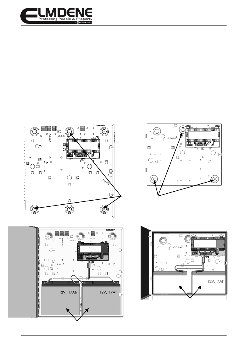
10) Mount the appropriate batteries as shown in Figure 2. Where a dual box solution is used all cabling
between the two boxes should be routed to use separate case entry/exit holes from other cabling and use
suitable bushes to protect the cables.
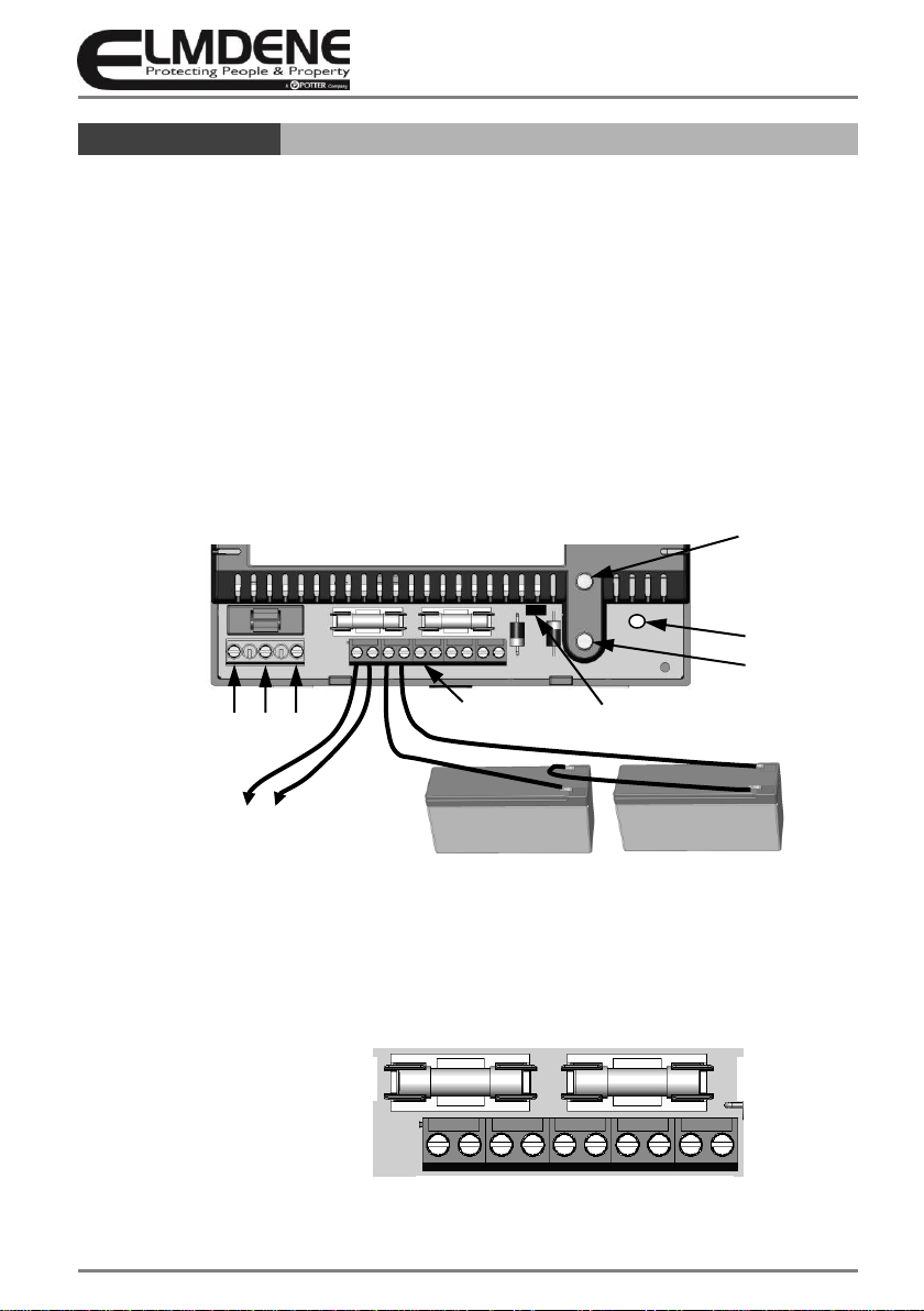
11) Connect the two 12 V standby batteries in series using the single cable provided. Connect the negative of
one battery to the positive of the other. See Figure 3.
CAUTION –DO NOT CONNECT the two remaining (free) battery terminals to each other!
12) Connect the PCB terminals Batt+ and Batt–to the free Positive and Negative terminals of the batteries
using the cables provided. See Figure 2 and 3. With the cable pair ALREADY screwed into the battery
terminals the FINAL connection MUST be to the battery itself.
CAUTION –significant energy can be released from an SLA battery. When connecting the last battery
lead, take extreme care to attach the cable ONLY to the correct terminal. Avoid shorting it to any other
terminal or conducting surface.
13) Verify that the yellow Fault LED does not flash (battery connection detected). Verify that the remote PSU
Fault monitor shows a closed contact.
14) Disconnect the mains power. Verify that the green Mains LED extinguishes and the Yellow Fault LED starts
to pulse (indicating that the PSE is running from its standby batteries).
15) If connected, verify that the EPS Fault monitor shows an open contact and the GEN PSU Fault monitor
shows a closed contact.
16) Verify that the standby batteries are now driving (supporting) the system load. Perform a full functional
test of system including full alarm condition Note: ensure batteries have sufficient charge to support the
system under full load.
Final
17) Reconnect the mains. Verify that the green Mains LED illuminates and the yellow Fault LED extinguishes.
18) If connected, verify that the EPS Fault monitor shows a closed contact and the GEN PSU Fault monitor
shows a closed contact.
19) Disconnect one of the battery leads, ensuring that no exposed section of conductor or connector is
allowed to contact exposed metal-work, other PSE terminals, or other battery terminals.
20) Verify that, in less than 1 minute, the yellow Fault LED starts to flash, and that the orange Diagnostic LED
flashes in a 2 pulse repeating pattern, (indicating that battery disconnection was detected).
21) Reconnect the battery lead and, after approximately 3 s, verify that that the Fault LED does not flash.
(Audible click can be heard as the battery relay closes, then a second click while the charger is tested.)
Note: If it is necessary to obtain confirmation of charging current; between steps 18 and 20, an ammeter
can be placed in series with the battery leads. Continue to observe caution with all exposed conductors
when inserting or removing the meter and when restoring normal battery wiring.
22) Close cover and secure using fastening screws provided.
OPERATING INSTRUCTIONS
In the event of loss of mains, a battery fault or a GEN PSU fault, the corresponding Fault signal contacts will
open.
If the output of the PSE fails, the cause of the failure should be investigated e.g. short circuit load,
connection of a deeply discharged battery. The fault should be rectified before restoring power to the PSE.
If any of the fuses require replacing, ensure the correct fuse rating and type is used.
MAINTENANCE
This unit is intended for use by Service Personnel only. There are NO USER SERVICEABLE parts inside.
There is no regular maintenance required of the PSE other than periodic testing, and replacement of the
standby battery. Reference should be made to the battery manufacturer's documentation to determine
typical/expected battery life with a view to periodic replacement of the battery.

8
Technical Support: +44(0)23 9269 6638 (option 3) PAK200582_02B August 2016 ©2016 ELMDENE INTERNATIONAL LTD
COMPLIANCE
This power supply unit meets the essential requirements of the
following EU Directives:
Functional Standard: EN54-4:1997 +A1 +A2
Environmental Class II
Certification Body: Underwriters Laboratory
Declaration of Performance: DOP2014/04
DOP2014/05
DISPOSAL OF PRODUCT AT END OF LIFE
This product falls within the scope of EU Directives 2012/19/EU Waste Electrical and Electronic Equipment
(WEEE) and 2006/66/EC (Battery). At the end of life, the product must be separated from the domestic
waste stream and disposed via an appropriate approved WEEE disposal route in accordance with all national
and local regulations.
Before disposal of the product, any batteries must be removed, and disposed separately via an appropriate
approved battery disposal route in accordance with all national and local regulations. Package used batteries
safely for onward transport to your supplier, collection point or disposal facility.
Caution: Risk of fire or explosion
if bare battery wires are allowed to touch.
See Specification for battery type information. The battery is marked with the crossed out wheelie bin
symbol, which may include lettering to indicate cadmium (Cd), lead (Pb), or mercury (Hg).
For more information see: www.recyclethis.info
The packaging supplied with this product may be recycled.
Please dispose of packaging accordingly.
CPR:
305/2011 EU
EMC:
2004/108/EC
Low Voltage:
2006/95/EC
WEEE:
2012/19/EU
RoHS:
2011/65/EU
0843
Elmdene International Ltd 3 Keel Close
Portsmouth PO35QD
14
0843-CPR-0214
EN54-4:1997 +A1 +A2
Power Supplies intended for use in fire detection
and fire alarm systems
Operational reliability - Pass
Durability
Temperature resistance - Pass
Vibration resistance - Pass
Electrical stability - Pass
Humidity resistance - Pass
This manual suits for next models
1
Table of contents
Other Potter Power Supply manuals