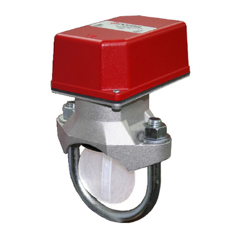
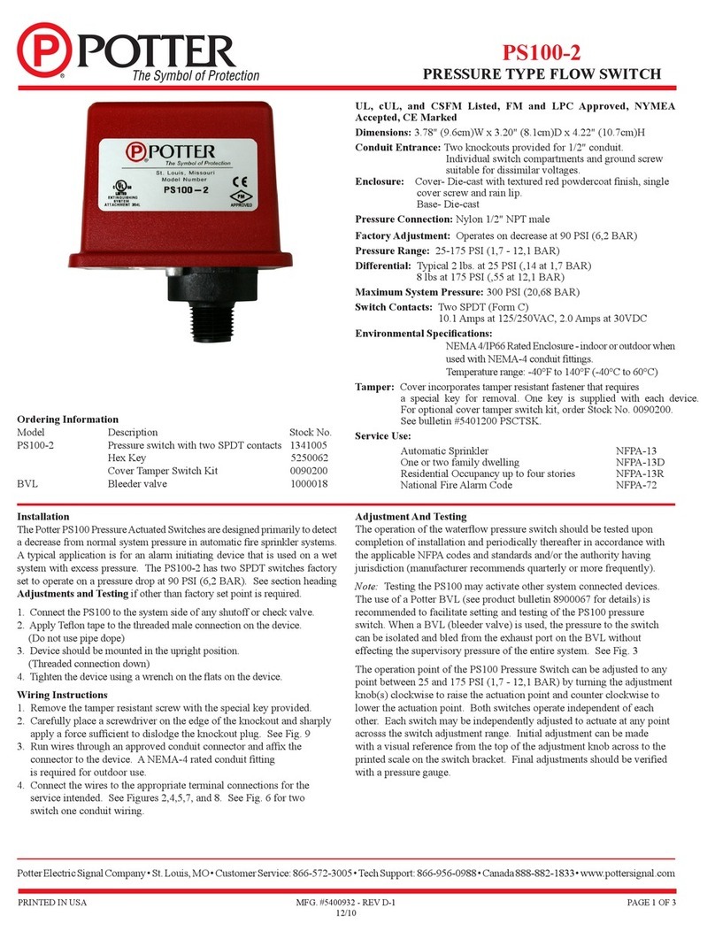
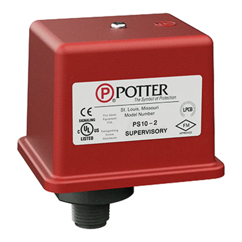
Potter RBVS User manual

RBVS
Universal Ball Valve/Solenoid
Coil Supervisory Switch
5401591 - REV A • 1/20 PAGE 1 OF 12
Potter Electric Signal Company, LLC • St. Louis, MO • Phone: 800-325-3936 • www.pottersignal.com
Description
The Model RBVS is designed to monitor the fully open or closed
position of a ball valve installed in a sprinkler system as well as monitor
the position of a coil on a solenoid for a preaction/deluge system. The
unit will t on most ball valves installed on back-ow-preventers and
alarm trim lines of dry, alarm, and deluge sprinkler valves. The switch
operates if the ball valve handle is moved from the normal position.
However, the switch does not track the position of the handle or ball.
When the ball valve handle is under the RBVS plunger, a spring-loaded
actuator will contact the valve handle. When the handle is moved from
the position, this actuator extends to the tripped position, and the RBVS
contacts change state, thereby opening or closing a circuit.
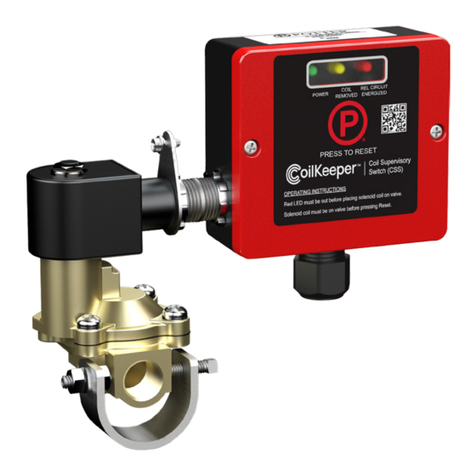
The unit also includes a small “L” bracket and “V” clamp to allow the
RBVS to mount directly to the nipple on the coil of a solenoid valve.
The plunger of the RBVS is actuated by the stud protruding through the
center of the coil, see Fig. 6. If a technician removes the coil from the
solenoid for testing, the RBVS will activate.
A cover tamper switch is available and is activated by the removal of the
RBVS housing cover. If an attempt is made to remove the RBVS by the
removal of the mounting brackets, the unit will be set into the tripped
mode by this action.
The RBVS can be mounted to the hex portion of the ball valve or back-
ow-preventer or to the adjoining pipe via two clamps. The RBVS is
shipped with three sets of mounting kits to accommodate various pipe
and valve sizes, refer to Table 1. An “L” shaped and offset bracket for
mounting the switch enclosure and an extension bracket add to the
mounting exibility of the RBVS. See “Typical Mounting Diagrams”
and “Installations and Operation” on following pages.
Technical Specications
Dimensions
With Large Clamps: 6” Lx 5” W x 5.3” H (15,2 cm L
x 12,7 cm W x 13,2 cm H)
With Small Clamps: 6” L x 4” W x 5.3” H (15,2 cm L
x 10,2 cm W x 13,2 cm H)
With Solenoid ClampAssembly: 5.1” L x 3.3”W x 6”
H ( 13 cm L x 8,38 cm W x 15,24 cm H)
Shipping
Weight 1.65 lbs.
Enclosure Non-Corrosive Composite Material
Temperature
Range -40°F to 150°F (-40°C to 65°C)
Optional
Housing Cover
Tamper
Cover incorporates tamper resistant fasteners
that requires a special key for removal. One key
is supplied with each device. For optional cover
tamper switch kit, order Stock No. 0090224. See
bulletin #5401598
Contact
Ratings
SPDT Contact: (Form C) 10.1A at 125 VAC
2A at 30 VDC Resistive
10 mAmps minimum at 24 VDC
SPDT Cover Tamper: 5A at 125 VAC
1mA at 5 VDC min
Environmental
Limitations
NEMA 4 (IP66)
Not for use in hazardous locations
Use suitably rated conduit and connections
Conduit
Entrance One Knockout for 1/2” conduit connection provided
(See Notice on Page 6)
*Specications subject to change without notice.
Features
• Assembled in USA
• Fits most lever/tee type ball valves up to 2”
• Fits most backow preventers up to 2”
• Operates on open or closed valves
• Includes mounting hardware to supervise coils on most
solenoids
• Accommodates up to 12 AWG wire
• Optional eld installed cover tamper switch kit (0090224)
• RoHS compliant
Important: This document contains important information on the installation and operation of the RBVS Universal Ball Valve/Solenoid Coil Supervisory
Switches. Please read all instructions carefully before beginning installation. A copy of this document is required by NFPA 72 to be maintained on site.
Before any work is done on the re sprinkler or re alarm system, the
building owner or their authorized representative shall be notied.
Before opening any closed valve, ensure that opening the valve
will not cause any damage from water ow due to open or missing
sprinklers, piping, etc.
NOTICE

5401591 - REV A • 1/20 PAGE 2 OF 12
Potter Electric Signal Company, LLC • St. Louis, MO • Phone: 800-325-3936 • www.pottersignal.com
RBVS
Universal Ball Valve/Solenoid
Coil Supervisory Switch
Mounting kits
Table 1: Mounting Congurations
Bag
Color
Item
No. Description Qty Illustration
White
Mounting
Kit
1CLAMP-VEE (SMALL) 2
2GRIPPER-RUBBER
(SMALL) 2
3SCREW-MACHINE #10-32
X 2-1/2” 2
4NUT-HEX #10-32 STEEL/
ZINC PLATED 2
Blue
Mounting
Kit
5CLAMP-VEE (LARGE) 2
6GRIPPER-RUBBER
(LARGE) 2
7SCREW-1/4-20 X 4” HEX
WASHER HD ZINC 2
8WASHER-SAE 1/4” 2
9NUT-HEX 1/4-20 2
Clear
Solenoid
Mounting
Kit
10 CLAMP-VEE SOLENOID
(SMALL) 1
Clear
Solenoid
Mounting
Kit
11 NUT-HEX #10-32 STEEL/
ZINC PLATED 2
12 SCREW-MACHINE #10-32
X 1-3/4” 2
Red
Bracket-
Hardware
Kit
13 “L” BRACKET-MOUNTING 1
14 BRACKET-EXTENSION 1
15 BRACKET-OFFSET 1
16 KEY-HEX TAMPERPROFF
HOLE ONE END 1
17 SCREW-TAMPER
RESISTANT #8-32 X 1/2” 4
18 BOLT 1/4-20 X 3/4 HEX HD
CAP SCREW 2
19 WASHER-SAE 1/4” 2
20 NUT-KEPS #8-32 HEX
STEEL / ZINC PLATED 2
21 BRACKET-SOLENOID
MOUNTING 1
Pipe Size/Valve Supervise Open/
Closed Valves
Valve
Handle
Type
Use Bag
Color
Use Item Number: Item # (xQty)
Clamps/Grippers
Item # (xQty)
Brackets
Item # Hardware: Item # (xQty)
1/2” to 3/4”
(12,5 to 19mm) Open
Lever
(Fig 1&2) White/Red
Mounting Kit
1(x2), 2(x2) 13 3(x2), 4( x2), 16, 17(x2), 18, 19
1(x2), 2(x2) 13, 14 3(x2), 4( x2), 16, 17(x2), 18(x2), 19(x2)
Tee (Fig 4) 1(x2), 2(x2) 13, 15 3(x2), 4( x2), 16, 17(x4), 18, 19, 20(x2)
1/2” to 3/4”
(12,5 to 19mm) Closed
Lever
(Fig 5) White/Red
Mounting Kit
1(x2), 2(x2) 13, 14 3(x2), 4( x2), 16, 17(x2), 18(x2), 19(x2)
Tee 1(x2), 2(x2) 13, 14, 15 3(x2), 4( x2), 16, 17(x4), 18(x2), 19(x2), 20(x2)
1” to 2”
(25 to 50mm) Open
Lever
(Fig 1&2) Blue/Red
Mounting Kit
5(x2), 6(x2) 13 7(x2), 8(x2), 9( x2), 16, 17(x2), 18, 19
5(x2), 6(x2) 13, 14 7(x2), 8(x2), 9( x2), 16, 17(x2), 18(x2), 19(x2)
Tee
(Fig 4) 5(x2), 6(x2) 13, 15 7(x2), 8(x2), 9( x2), 16, 17(x4), 18, 19, 20(x2)
1” to 2”
(25 to 50mm) Closed
Lever
(Fig 5) Blue/Red
Mounting Kit
5(x2), 6(x2) 13, 14 7(x2), 8(x2), 9( x2), 16, 17(x2), 18(x2), 19(x2)
Tee 5(x2), 6(x2) 13, 14, 15 7(x2), 8(x2), 9( x2), 16, 17(x4), 18(x2), 19(x2), 20(x2)
1/2” Solenoid
Conduit
“Nipple”
-
1/2
Solenoid
Valve
(Fig 6)
White/Clear/
Red Solenoid
Mounting Kit
1, 2(x2), 10 13, 21 11(x2), 12(x2), 16, 17(x4), 18, 19, 20(x2)

5401591 - REV A • 1/20 PAGE 3 OF 12
Potter Electric Signal Company, LLC • St. Louis, MO • Phone: 800-325-3936 • www.pottersignal.com
RBVS
Universal Ball Valve/Solenoid
Coil Supervisory Switch
Installation on Lever Handle Valves
1. Select Clamp Mounting Kit (clamps and screws) based upon pipe/valve
size, see Mounting Conguration Table 1 (see page 2).
Note: See Fig. 1 & 2 for utilization of extension bracket.
2. Insert rubber clamp grippers into clamps, see Fig. 1 & 2.
3. Insert screws into mounting clamp-vee, then place over pipe.
Note: If using Blue Mounting Kit, place washer on screw before
inserting into clamp-vee.
4. Place second clamp-vee over the screws from step 3. Then thread
hex nuts onto the screws, but do not fully tighten, (be sure hex nuts
seat properly in clamp-vee hex recesses).
Note: Some installations may require one of the mounting screws
to
be inserted from the bottom of the brackets and then trimmed to
allow the extension bracket to clear. See Fig. 3.
5. Position clamp-vee assembly so that the RBVS actuator will
contact the valve handle approximately 1” from its inside end.
See Fig 1 for approximate location. Make sure the top face of the
clamp-vee assembly is parallel with the ball valve handle when
tightening screws.
6. Tighten screws alternately to 30 in-lbs. (minimum) of torque.
7. If necessary, for positioning, attach bracket-extension from the Red
bag to the top clamp-vee using ¼-20 X ¾ Hex bolt and washer,
but do not fully tighten. See Fig 2. If bracket-extension is not
necessary, skip to number 9.
8. Attach “L” bracket-mounting to bracket-extension using ¼-20 X
¾” Hex bolt and washer, but do not fully tighten. See Fig 2. Skip
to number 10 if bracket-extension is necessary.
9. Attach “L” bracket-mounting from the Red bag directly to the top
clamp-vee, See Fig 1, using ¼-20 X ¾” Hex bolt and washer, but
do not fully tighten.
10. Attach RBVS switch enclosure to “L” bracket-mounting slot with
two tamper resistant screw from the Red bag, but do not tighten
fully.
11. Place ball valve in the desired position to monitor.
12. Position “L” bracket-mounting so that it contacts the back edge of the
valve handle and secure its hex bolt. It may be necessary to close/open
valve to access this bolt.
13. Slide loosely assembled RBVS switch enclosure to a position that
permits the actuator to contact the valve handle. Cut and remove
the plastic coating from the ball valve handle to allow the RBVS
actuator to contact and be activated by the metal of the handle.
14. If bracket-extension is used, secure its hex bolt.
15. Remove the RBVS switch enclosure cover.
16. Slide RBVS enclosure down “L” bracket-mounting until the
housing contacts valve handle. Securely tighten the two tamper
resistant screws. This will ensure the actuator is fully depressed.
17. Close and open the valve to verify operation. The valve handle may
“trim” some material off the actuator during the rst few operations.
18. Place valve in supervised position.
APPROXIMATE ACTUATOR
LOCATION
ON HANDLE
COMMON
NORMALLY OPEN
NORMALLY CLOSED
TAMPER SWITCH WIRE
STRAIN RELIEF SLOT
"L" BRACKET-MOUNTING (13)
COVER REMOVED
CLAMPS (1,5)
SCREW-MACHINE (3,7)
BALL VALVE BEING MONITORED IN THE OPEN POSITION
1/2"-2"
BALL VALVE
BOLT 1/4-20 (18)
WASHER 1/4" (19)
CLAMP GRIPPERS (2,6)
ACTUATOR
Internal Components/Typical Lever
Handle Valve Mounting
Typical Lever Handle Valve Mounting
Fig 2
Fig 1
19. Wire main switch and optional tamper switch (if required). If
required, carefully route tamper switch wires through strain relief
slot in switch enclosure. Fully seat the wires into the bottom of the
channel. See Fig. 1.
20. Replace RBVS switch enclosure cover and securely tighten cover
screws to 10 in-lbs minimum. See notice on page 6.
SWITCH ENCLOSURE
CLAMP GRIPPERS (2,6)
BALL VALVE BEING MONITORED IN THE OPEN POSITION
SCREW MACHINE (3,7)
LENGTH WITHOUT
BRACKET EXTENSION
4.5”
TAMPER
RESISTANT
SCREW
LENGTH
6”
HEX BOLT (18)
WASHER (19) SCREW-TAMPER
RESISTANT (17)
HEIGHT
5.3” (SMALL AND LARGE)
WIDTH
4” (SMALL)
5” (LARGE)
CLAMP-VEE (1,5)
“L” BRACKET-MOUNTING (13)
BRACKET-EXTENSION (14)
(IF NECESSARY)
1/2” - 2”
BALL VALVE
WASHER FROM
BLUE MOUNTING KIT (8)

5401591 - REV A • 1/20 PAGE 4 OF 12
Potter Electric Signal Company, LLC • St. Louis, MO • Phone: 800-325-3936 • www.pottersignal.com
RBVS
Universal Ball Valve/Solenoid
Coil Supervisory Switch
Installation on Tee Handle Valves
1. Select Clamp Mounting Kit (clamps and screws) based upon pipe/valve
size, see Mounting Conguration Table 1.
2. Insert rubber clamp grippers into clamps, See Fig. 4.
3. Insert screws into mounting clamp-vee, then place over pipe.
Note: If using Blue Mounting Kit, place washer on screw before
inserting into clamp-vee.
4. Place second clamp-vee over the screws from step 3. Then thread
hex nuts onto the screws, but do not fully tighten, (be sure hex nuts
seat properly in clamp hex recesses).
5. Position clamp-vee assembly so that the RBVS actuator will
contact the tee-valve handle approximately ½” from the end of
the tee-handle. See Fig 4 for approximate location. Make sure the
top face of the clamp-vee assembly is parallel with the tee handle
when tightening screws.
6. Tighten screws alternately to 30 in-lbs. (Minimum) of torque.
7. Loosely attach “L” bracket-mounting parallel to the pipe with the
vertical edge facing the tee handle by using the 1/4-20 x 3/4” bolt
and washer out of the Red bag. Then loosely attach the bracket-
offset to the “L” bracket-mounting
8. Attach RBVS switch enclosure to the bracket-offset with two
tamper resistant screws from the Red bag, but do not tighten fully.
See Fig. 4.
9. Place Tee handle valve in the desired position to monitor.
10. Slide loosely assembled RBVS switch enclosure to a position that
permits the actuator to contact the tee handle. Cut and remove
the plastic coating from the ball valve handle to allow the RBVS
actuator to contact and be activated by the metal of the handle.
11. Tighten “L” bracket-mounting hex bolt to 30 in-lbs. (Minimum)
of torque.
12. Remove the RBVS switch enclosure cover.
13. Slide RBVS enclosure down “L” bracket-mounting until the
housing contacts the tee-valve handle. Securely tighten the two
tamper resistant screws. This will ensure the actuator is fully
depressed.
BRACKET-EXTENSION (14)
RBVS
PIPE
SOME INSTALLATIONS MAY
CAUSE INTERFERENCE
BETWEEN MOUNTING BOLT AND
BRACKET EXTENSION. INSTALL
BOLT FROM BOTTOM AND TRIM AS
NEEDED TO CORRECT
BALL VALVE BEING MONITORED IN THE OPEN POSITION
Fig 3
CLAMP GRIPPERS (2,6)
BOLT 1/4-20
(18)
“L” BRACKET-
MOUNTING
(13)
TEE HANDLE VALVE BEING MONITORED IN THE OPEN POSITION
NUT-KEPS (20)
WASHER 1/4” (19)
RBVS SWITCH ENCLOSURE
BRACKET-OFFSET
(15)
CLAMPS
(1,5)
TAMPER RESISTANT
SCREWS
(17)
Alternate Lever Handle Valve Mounting
Typical Tee Handle Ball Valve
Mounting
Fig 4
14. Close and open the valve to verify operation. The valve handle may
“trim” some material off the actuator during the rst few operations.
15. Place tee-handle valve in supervised position.
16. Wire main switch and tamper switch (if required). If required,
carefully route tamper switch wires through strain relief slot
in switch enclosure. Fully seat the wires into the bottom of the
channel. See Fig. 1.
17. Replace RBVS switch enclosure cover and securely tighten cover
screws to 10 in-lbs minimum. See notice on page 6.
RBVS SWITCH ENCLOSURE
"L" BRACKET-MOUNTING (13)
TAMPER RESISTANT SCREWS (17)
BRACKET EXTENSION (14)
GRIPPERS (2,6)
CLAMPS (1,5)
SCREWS-MACHINE (3,7)
1/2"-2" BALL VALVE
WASHER 1/4" (19)
BOLT 1/4"-20 (18)
Typical Lever Handle Valve Mounted
in the Closed Position
Fig 5

5401591 - REV A • 1/20 PAGE 5 OF 12
Potter Electric Signal Company, LLC • St. Louis, MO • Phone: 800-325-3936 • www.pottersignal.com
RBVS
Universal Ball Valve/Solenoid
Coil Supervisory Switch
TYPICAL STANDARD 1/2”
SOLENOID VALVE SHOWN
CLAMP-VEE SOLENOID (SMALL) (10)
1/2 NPT NIPPLE CONNECTION
SCREW-MACHINE (12)
CLAMP-VEE (SMALL) (1)
NUT-KEPS (20)
“L” BRACKET-MOUNTING
(13)
BRACKET-SOLENOID MOUNTING (21)
SWITCH ENCLOSURE
TAMPER RESISTANT SCREW
(17)
ACTUATOR ACTIVATED ON STUD
IN SOLENOID COIL
INSERT NUTS #10-32
INTO BOTTOM CLAMP (11)
Typical Solenoid Valve Mounting
Press Fit Hex Slots
Fig 6
Fig 7
Installation on Solenoid Valve
1. For solenoid mounting use Bag colors, White, Clear and Red. See
Mounting Conguration Table 1 (see page 2).
2. Use one clamp-vee (small) from the white bag as the top clamp and the
(clamp-vee solenoid) as the bottom clamp from the clear bag. See Fig 6.
3. Insert both small rubber grippers from the white bag into both clamps.
4. Insert two, #10-32 hex nuts from the clear bag into the bottom press t
hex slots of the (clamp-vee solenoid). Make sure the hex nuts are fully
seated in the hex slots. See Fig 7.
5. Insert screws into top mounting clamp-vee (small).
6. Place (clamp-vee solenoid) on bottom of the solenoid nipple.
7. Place top mounting clamp-vee (small) over solenoid nipple and insert the
screws into (clamp-vee solenoid). Make sure the top of the clamp-vee
(small) is parallel with the top of the solenoid coil. Tighten alternately to
30 in-lbs. (minimum) of torque.
8. Attach the “L” bracket-mounting to the top clamp-vee using the ¼-20 X
¾” hex bolt and washer out of the Red bag. Do not fully tighten hex bolt.
Make sure vertical slot on the “L” mounting-bracket is closer to the center
of the solenoid coil. See g 6.
9. Attach the (bracket-mounting solenoid) from the Red bag to the
RBVS through the two smaller slots in the bracket with two tamper
resistant screws.
10. Slide the bracket up against the stop on the back of the RBVS and
tighten the tamper resistant screws.
11. Using two tamper resistant screws and keps nuts, loosely attach
the (bracket-mounting solenoid) to the “L” bracket-mounting.
See Fig 6.
12. Remove the RBVS switch enclosure cover.
13. Position the RBVS so the actuator is directly above the coil
mounting stud in the center of the solenoid coil. Tighten the hex
bolt on the “L” mounting-bracket.
14. Slide the RBVS down the “L” mounting-bracket so the actuator is
activated by the stud in the solenoid coil.
15. While holding the RBVS enclosure down so that the actuator is
depressed by the coil mounting stud, securely tighten the two
tamper resistant screws and keps nuts.
16. Wire main switch and tamper switch (if required). If required,
carefully route tamper switch wires through strain relief slot
in switch enclosure. Fully seat the wires into the bottom of the
channel. See Fig 1.
17. Replace RBVS switch enclosure cover and securely tighten cover
screws to 10 in-lbs minimum. See notice on page 6.
Typical Electrical Connections
CLAMP-VEE SOLENOID (10)
GRIPPER-RUBBER (SMALL) (2)
SCREW-MACHINE
#10-32 X 1 3/4" (12)
NUT HEX #10-32 (11)

5401591 - REV A • 1/20 PAGE 6 OF 12
Potter Electric Signal Company, LLC • St. Louis, MO • Phone: 800-325-3936 • www.pottersignal.com
RBVS
Universal Ball Valve/Solenoid
Coil Supervisory Switch
Model Description Stock No.
RBVS Universal Ball Valve/Solenoid Coil
Switch 1000065
Cover Tamper Kit (Optional) 0090224
Ordering Information
Testing
The RBVS and its associated protective monitoring system should be tested
in accordance with applicable NFPA codes and standards and/or the authority
having jurisdiction (manufacturer recommends quarterly or more frequently).
Switch Terminal Connections
Clamping Plate Terminal
An uninsulated section of a single conductor should not be looped around the terminal
and serve as two separate connections. The wire must be severed, thereby providing
supervision of the connection in the event that the wire become dislodged from under
the terminal. Failure to sever the wire may render the device inoperable risking severe
property damage and loss of life.
Do not strip wire beyond 3/8” of length or expose an uninsulated conductor beyond
the edge of the terminal block. When using stranded wire, capture all strands under
the clamping plate.
Supervisory switches have a normal service life of 10-15 years.
However, the service life may be signicantly reduced by local
environmental conditions.
Engineering Specication
UL, cUL Listed and FM Approved supervisory switch specically
manufactured for monitoring ball valves shall be furnished and installed on
¼ turn ball valves that can be used to shut off the ow of water to a portion
of the sprinkler system including the trim piping on alarm check, dry pipe
or preaction/deluge valves. Locations shall be as indicated on drawings and
plans and as required by applicable local and national codes and standards. The
supervisory switch shall monitor the position of the handle on the valve and be
capable of monitoring a valve in the open or closed position. Movement of the
valve handle from normal shall activate the supervisory switch. Restoration
of the valve handle shall cause the supervisory switch to automatically restore
to normal. There shall not be any tools or extra steps required to restore the
supervisory switch to normal. The enclosure shall be corrosion resistant and
rated NEMA 4. The cover of the device shall be secured by the use of tamper
proof screws. All mounting hardware necessary for the installation on valves
ranging in sizes from ½” – 2” including backow preventers shall be included.
Also included shall be hardware to allow the switch to be mounted to a solenoid
valve to provide the ability to supervise the position of the coil on the solenoid.
The switch shall mount to the wiring nipple of the coil and the switch plunger
shall be depressed by the coil enclosure. Removal of the coil shall activate the
switch. Each ball valve switch shall contain 1 SPDT contact rated 10.1A at
125 VAC and 2A at 30 VDC resistance. Ball valve supervisory switch shall
be model RBVS as manufactured by Potter Electric Signal Company LLC.
Tamper Switch Connections
N.O
EOLR
N.C
COM.
COVER
TAMPER
COVER TAMPER & RBVS CONNECTED
TO THE SAME ZONE ON THE FACP
COM.
FACP
RBVS
All conduit and connectors selected for the installation of this product
shall be suitable for the environment for which it is to be used and shall
be installed to the manufacturer’s installation instructions. For NEMA 4
installations, the cover screws are recommended to be tightened to 10 in-lbs
minimum.

RBVS
Clapet à bille universel/électrovanne
Interrupteur de surveillance des crosses
5401591 - REV A • 1/20 PAGE 7 DE 12
Potter Electric Signal Company, LLC • St. Louis, MO • Téléphone : 800-325-3936 • www.pottersignal.com
Description
Le modèle RBVS est conçu pour surveiller la position entièrement
ouverte ou fermée d'un clapet à bille dans un système de gicleurs ainsi
que de surveiller la position d'une bobine sur une électrovanne pour
un système de pré-action/de déluge. L'unité s'adaptera à la plupart
des clapets à bille installés sur les disconnecteurs hydrauliques et les
lignes de détourage d'alarme des vannes de gicleurs secs, d'alarme et
de déluge. L'interrupteur fonctionne si la poignée du clapet à bille est
déplacée de la position normale. Toutefois, l'interrupteur ne consigne
pas l'emplacement de la poignée ou de la bille. Lorsque la poignée
du clapet à bille se trouve en dessous du piston RBVS, un actionneur
actionné à ressort entrera en contact avec la poignée de la vanne.
Lorsque la poignée est déplacée de la position, cet actionneur s'étend à
la position déclenchée, et les contacts RBVS changent d'état, ouvrant
et fermant ainsi le circuit.
L'unité comprend également un petit support de xation en « L » et une
pince en « V » pour permettre au RBVS d'être directement monté sur
le raccord leté de la bobine de l'électrovanne. Le piston du RBVS est
actionné par le goujon saillant via le centre de la bobine, voir la Figure
6. Si le technicien enlève la bobine de l'électrovanne à des ns de test,
le RBVS sera alors activé.
Une interrupteur de protection du couvercle est disponible et activé par
l'élimination du couvercle du boîtier RBVS. Si l'on essaie d'enlever
le RBVS en enlevant les supports de xation, l'unité entrera alors en
mode « déclenché ».
Le RBVS peut être xé sur la portion hexagonale du clapet à bille
ou sur le disconnecteur hydraulique ou sur le tuyau adjacent via
deux pinces de xation. Le RBVS est expédié avec trois ensembles
de trousses de montage pour accommoder les différentes tailles de
tuyau et de vanne, veuillez vous référer au Tableau 1. Un support de
décalage en forme de « L » pour monter l'enceinte de l'interrupteur et
un support d'extension apporte encore plus de exibilité de montage au
RBVS. Veuillez consulter les « Diagrammes de montage typiques » et
« Installations et fonctionnement » sur les pages suivantes.
Spécications techniques
Dimensions
Avec des grandes pinces : 6 po x 5 po x 5,3 po
(15,2 cm L x 12,7 cm l x 13,2 cm H)
Avec des petites pinces : 6 po x 4 po x 5,3 po
(15,2 cm L x 10,2 cm l x 13,2 cm H)
Avec l'assemblage de la pince à électrovanne :
5,1 po x 3,3 po x 6 po (13 cm Lx 8,38 cm l x 15,24 cm H)
Poids d'expédition 0,74 kg (1,65 lb)
Enceinte Matériau composite non corrosif
Plage de
températures -40°F à 150°F (-40°C à 65°C)
Enceinte de
protection du
couvercle en
option
Le boîtier comprend des attaches de xation
difciles à falsier qui nécessitent une clé spéciale
pour l'élimination. Une clé est fournie avec chaque
appareil. Pour le kit de protection du couvercle
d'interrupteur en option, veuillez commander le
numéro de pièce 0090224.
Voir le bulletin No. 5401598
Valeurs de contact
Contact SPDT : (Formulaire C) 10,1 A à 125 V CA
2 A à 30 V CC résistif
10 ampère minimum à 24 V CC
Protection du couvercle SPDT : 5 A à 125 V CA
1 mA à 5 V CC min
Limitations
environnementales
NEMA 4 (IP66)
Ne peut être utilisé dans les environnements dangereux
Utiliser un conduit et de connecteurs adaptés
Entrée de conduit Deux alvéoles défonçables fournies pour
la connexion du conduit de 1/2 po
(Voir l'avis à la page 6)
*Spécications susceptibles d'être modiées sans notication préalable.
Caractéristiques
• Assemblé aux États-Unis
• S'adapte à la plupart des clapets à bille de type levier
ou en « t » jusqu'à 2 po
• S'adapte à la plupart des disconnecteurs hydrauliques
jusqu'à 2 po
• Fonctionne sur les vannes ouvertes ou fermées
• Comprend les matériaux de montage pour surveiller
les bobines sur la plupart des électrovannes
• Accommode les ls jusqu'à un calibre de 12 AWG
• Kit de protection du couvercle d'interrupteur installé
en option (0090224)
• Conforme à RoHS
Important : Ce document contient des informations importantes concernant l’installation et le fonctionnement des interrupteurs de surveillance du
clapet à bille universel RBVS/de la bobine de solénoïde. Veuillez lire attentivement l’intégralité des instructions avant de commencer l’installation. Le
NFPA 72 exige qu'une copie de ce document soit gardée sur le site.
Avant d’effectuer un travail sur l'extincteur ou sur le système
d'alarme incendie, le propriétaire du bâtiment ou son représentant
ofciel doit être prévenu. Avant d'ouvrir une vanne fermée, assurez-
vous que cela n’altérera pas le débit à cause d'un extincteur ouvert
ou manquant ou l'absence de tuyaux, etc.
AVIS

5401591 - REV A • 1/20 PAGE 8 DE 12
Potter Electric Signal Company, LLC • St. Louis, MO • Téléphone : 800-325-3936 • www.pottersignal.com
RBVS
Clapet à bille universel/électrovanne
Interrupteur de surveillance des crosses
Trousses de montage
Tableau 1 : Congurations de montage
Couleur du
sac
N°
d'article Description Quantité Illustration
Trousse de
montage
blanche
1COLLIER DE SERRAGE EN V (PETIT) 2
2PINCE EN CAOUTCHOUC (PETITE) 2
3MACHINE À VIS NO. 10-32 X 2-1/2 PO 2
4ÉCROU HEXAGONAL NO. 10-32 EN
MÉTAL/ PLAQUÉ ZINC 2
Trousse de
montage
bleue
5COLLIER DE SERRAGE EN V
(LARGE) 2
6PINCE EN CAOUTCHOUC (LARGE) 2
7VIS-1/4-20 X RONDELLE
HEXAGONALE DE 4 PO HD EN ZINC 2
8RONDELLE-SAE 1/4 PO 2
9ÉCROU HEXAGONAL 1/4-20 2
Tousse de
montage de
solénoïde
transparent
10 ÉLECTROVANNE DE SERRAGE
EN V (PETITE) 1
Tousse de
montage de
solénoïde
transparent
11
ÉCROU HEXAGONAL NO. 10-32 EN
MÉTAL/
PLAQUÉ ZINC
2
12 MACHINE À VIS NO. 10-32 X 1-3/4 PO 2
Support
rouge -
Trousse de
montage
13 SUPPORT DE FIXATION EN « L » 1
14 EXTENSION DU SUPPORT 1
15 COMPENSATION DU SUPPORT 1
16
CLÉ - HEXAGONALE
ANTIVIOLABLE TROU DE
L'EXTRÉMITÉ
1
17 VIS INVIOLABLE NO. 8-32 X 1/2 PO 4
18 BOULON 1/4-20 X 3/4 HEX HD
CAPUCHON DE VIS 2
19 RONDELLE-SAE 1/4 PO 2
20
ÉCROU KEPS NO. 8-32
HEXAGONAUX EN MÉTAL/ PLAQUÉ
ZINC
2
21 SUPPORT - FIXATION DU
SOLÉNOÏDE 1
Taille du tuyau/
vanne
Vannes en position
supervisée
ouverte/fermée
Type de poignée
de la vanne Utilisez la couleur
du sac
Utilisez le numéro d'article : Numéro d'article (quantité)
Colliers/pinces
Numéro d'article
(quantité)
Supports
Numéro
d'article
Matériel : Numéro d'article (quantité)
1/2 po à 3/4 po
(12,5 à 19 mm) Ouvrir
Levier
(Image 1 et 2) Trousse de xation
rouge/blanche
1(x2), 2(x2) 13 3(x2), 4( x2), 16, 17(x2), 18, 19
1(x2), 2(x2) 13, 14 3(x2), 4( x2), 16, 17(x2), 18(x2), 19(x2)
Voir (Image 4) 1(x2), 2(x2) 13, 15 3(x2), 4( x2), 16, 17(x4), 18, 19, 20(x2)
1/2 po à 3/4 po
(12,5 à 19 mm) Fermé
Levier
(Image 5) Trousse de xation
rouge/blanche
1(x2), 2(x2) 13, 14 3(x2), 4( x2), 16, 17(x2), 18(x2), 19(x2)
Tee 1(x2), 2(x2) 13, 14, 15 3(x2), 4( x2), 16, 17(x4), 18(x2), 19(x2), 20(x2)
1 à 2 po
(25 à 50 mm) Ouvrir
Levier
(Image 1 et 2) Trousse de xation
rouge/bleue
5(x2), 6(x2) 13 7(x2), 8(x2), 9( x2), 16, 17(x2), 18, 19
5(x2), 6(x2) 13, 14 7(x2), 8(x2), 9( x2), 16, 17(x2), 18(x2), 19(x2)
Tee
(Image 4) 5(x2), 6(x2) 13, 15 7(x2), 8(x2), 9( x2), 16, 17(x4), 18, 19, 20(x2)
1 à 2 po
(25 à 50 mm) Fermé
Levier
(Image 5) Trousse de xation
rouge/bleue
5(x2), 6(x2) 13, 14 7(x2), 8(x2), 9( x2), 16, 17(x2), 18(x2), 19(x2)
Tee 5(x2), 6(x2) 13, 14, 15 7(x2), 8(x2), 9( x2), 16, 17(x4), 18(x2), 19(x2), 20(x2)
Raccord leté de
conduit solénoïde
de 1/2 po -Électrovanne de
1/2 po
(Image 6)
Tousse de
montage de
solénoïde blanche/
transparente/rouge
1, 2(x2), 10 13, 21 11(x2), 12(x2), 16, 17(x4), 18, 19, 20(x2)

5401591 - REV A • 1/20 PAGE 9 DE 12
Potter Electric Signal Company, LLC • St. Louis, MO • Téléphone : 800-325-3936 • www.pottersignal.com
RBVS
Clapet à bille universel/électrovanne
Interrupteur de surveillance des crosses
Installation sur les vannes de la poignée à levier
1. Veuillez sélectionner la trousse de montage par serrage (pinces et
vis) en fonction de la taille du tuyau/vanne, consulter le Tableau 1 de
Conguration de montage (voir la page 2).
Remarque : Voir Image 1 et 2 pour l'utilisation du support d'extension.
2. Insérez les pinces de la griffe en caoutchouc sur les pinces, voir Image
1 et 2.
3. Insérez les vis sur le collier de serrage en « V », puis placer par-dessus
le tuyau.
Remarque : Si vous utilisez la Trousse de xation bleue, placez la
rondelle sur la vis avant d'insérer le collier de serrage en « V ».
4. Placez le second collier de serrage en « V » par-dessus les vis à l'étape
3. Puis faites tourner les boulons hexagonaux sur les vis, mais ne
pas serrer complètement (assurez-vous que les boulons hexagonaux
soient confortablement assis dans les cavités hexagonales du collier
de serrage en « V »).
Remarque : Certaines installations peuvent exiger que l'une des vis
de montage soit
insérée à partir du fond des supports puis découpée
an de permettre au support d'extension d'être libre. Voir Image 3.
5. Placez l'assemblage du collier de serrage en an que l'actionneur
RBVS entre en contact avec la poignée de la vanne à environ 1 po de
son extrémité intérieure. Voir l'Image 1. pour connaître l'emplacement
approximatif. Veillez à ce que la face supérieure de l'assemblage du
collier de serrage en « V » soit parallèle à la poignée du clapet à bille
lorsque vous serrez les vis.
6. Serrez les vis jusqu'à environ 30 lb-po. (minium) de couple.
7. Le cas échéant, lors du positionnement, placez l'extension de support
du Sac rouge au haut du collier de serrage en « V » à l'aide d'un boulon
et d'une rondelle hexagonale ¼-20 X ¾, mais ne pas serrer entièrement.
Voir image 2. Si l'extension de support n'est pas nécessaire, passez
alors au numéro 9.
8. Fixez le support de montage en « L » à l'extension du support à l'aide
d'un boulon et d'une rondelle hexagonale ¼-20 X ¾, mais ne pas
serrer entièrement. Voir image 2. Passez au numéro 10 si l'extension
de support n'est pas nécessaire.
9. Fixez le support de montage en « L » du Sac rouge directement au haut
du collier de serrage en « V », voir l'Image 1, à l'aide d'un boulon et
d'une rondelle hexagonale ¼-20 X ¾, mais ne pas serrer entièrement.
10. Fixez l'enceinte de l'interrupteur RBVS à la fente du support de
montage en « L » à l'aide de deux vis inviolables du Sac rouge, mais
ne pas serrer entièrement.
11. Placez le clapet à bille dans la position souhaitée pour surveiller.
12. Placez le support de montage en « L » an qu'il entre en contact avec
le bord arrière de la poignée de la vanne et xez son boulon hexagonal.
Dans certains cas, il peut être nécessaire de fermer/d'ouvrir la vanne
an d'accéder au boulon.
13. Faites glisser l'enceinte de l'interrupteur RBVS montée sans serrage
à une position qui permet à l'actionneur d'entrer en contact avec la
poignée de la vanne. Découpez et enlevez le revêtement en plastique
de la poignée du clapet à bille an de permettre à l'actionneur RBVS
d'entrer en contact et d'être activé par le métal de la poignée.
14. Si une extension de support est utilisée, veuillez alors xer son boulon
hexagonal.
15. Enlevez le couvercle de l'enceinte de l'interrupteur RBVS.
16. Faites glisser l'enceinte RBVS dans le support de montage en « L »
jusqu'à ce que le boîtier entre en contact avec la poignée de la vanne.
Serrez fermement grâce à deux vis inviolables. Ceci garantira que
l'actionneur est entièrement enfoncé.
17. Fermez et ouvrez la vanne pour vérier le fonctionnement. La poignée
de la vanne peut « découper » un peu de matériau de l'actionneur au
cours des premières opérations.
18. Placez la vanne en position supervisée.
EMPLACEMENT
APPROXIMATIF DE
L'ACTIONNEUR SUR LA
POIGNÉE
COMMUN
NORMALEMENT OUVERT
NORMALEMENT FERMÉ
FENTE DE SOULAGEMENT
POUR LA JAUGE
EXTENSOMÉTRIQUE
DE L'INTERRUPTEUR
D'AUTOPROTECTION
SUPPORT DE
FIXATION EN « L » (13)
COUVERCLE ENLEVÉ
COLLIERS DE
SERRAGE (1,5)
MACHINE À VIS (3,7)
CLAPET À BILLE SURVEILLÉ EN POSITION OUVERTE
CLAPET À BILLE DE 1/2-2 PO
BOULON DE
1/4-20 PO (18)
RONDELLE
DE 1/4 PO (19)
PINCE DE
SERRAGE (2,6)
ACTIONNEUR
Composantes internes/montage typique de la
vanne de la poignée à levier
Montage typique de la vanne de la poignée à levier
Image 2
Image 1
19. Câblez l'interrupteur principal et l'interrupteur inviolable en option
(le cas échéant). Si cela est nécessaire, positionnez avec soin les
câbles de l'interrupteur via la fente de soulagement dans l'enceinte de
l'interrupteur. Déposez entièrement les câbles au fond du canal. Voir
Image 1.
20. Remplacez l'enceinte de l'interrupteur RBVS et serrez fermement les
vis jusqu'à 10 lb-po minimum. Voir l'avis à la page 6.
ENCEINTE DE L'INTERRUPTEUR
PINCE DE SERRAGE (2,6)
CLAPET À BILLE SURVEILLÉ EN POSITION OUVERTE
MACHINE À VIS (3,7)
LONGUEUR SANS
L'EXTENSION DE
SUPPORT 11,4 CM (4,5 PO)
VIS INVIOLABLE
LONGUEUR DE
15,2 CM (6 PO)
BOULON
HEXAGONAL (18)
RONDELLE (19) VIS INVIOLABLE (17)
HAUTEUR DE 13,4 CM (5,3 PO)
(PETITE ET LARGE)
LARGEUR D
10 CM (4 PO)
(PETITE)
ET DE
12,7 CM (5 PO) (LARGE)
COLLIERS DE
SERRAGE EN « V » (1,5)
SUPPORT DE FIXATION EN « L » (13)
EXTENSION DU SUPPORT (14)
(LE CAS ÉCHÉANT)
CLAPET À BILLE DE 1/2 - 2 PO
RONDELLE DE LA TROUSSE DE FIXATION BLEUE (8)

5401591 - REV A • 1/20 PAGE 10 DE 12
Potter Electric Signal Company, LLC • St. Louis, MO • Téléphone : 800-325-3936 • www.pottersignal.com
RBVS
Clapet à bille universel/électrovanne
Interrupteur de surveillance des crosses
Installation sur les vannes de la poignée en « T »
1. Veuillez sélectionner la trousse de montage par serrage (pinces et
vis) en fonction de la taille du tuyau/vanne, consulter le Tableau 1 de
Conguration de montage.
2. Insérez les pinces de la griffe en caoutchouc sur les pinces, voir
l'image 4.
3. Insérez les vis sur le collier de serrage en « V », puis placer par-dessus
le tuyau.
Remarque : Si vous utilisez la Trousse de xation bleue, placez la
rondelle sur la vis avant d'insérer le collier de serrage en « V ».
4. Placez le second collier de serrage en « V » par-dessus les vis à l'étape
3. Puis faites tourner les boulons hexagonaux sur les vis, mais ne
pas serrer complètement (assurez-vous que les boulons hexagonaux
soient confortablement assis dans les cavités hexagonales du collier
de serrage).
5. Placez l'assemblage du collier de serrage an que l'actionneur RBVS
entre en contact avec la poignée de la vanne en « T » à environ ½ po
de l'extrémité de la poignée en « T ». Voir l'Image 4 pour connaître
l'emplacement approximatif. Veillez à ce que la face supérieure de
l'assemblage du collier de serrage en « V » soit parallèle à la poignée
en « T » lorsque vous serrez les vis.
6. Serrez les vis jusqu'à environ 30 lb-po. (minium) de couple.
7. Attachez légèrement le support de montage en « L » parallèle au tuyau
avec le bord vertical face à la poignée en « T » à l'aide du boulon et de
la rondelle de 1/4-20 x 3/4 po du Sac rouge. Puis xez légèrement la
compensation du support au support de montage en « L ».
8. Fixez l'enceinte de l'interrupteur RBVS à la fente du support de
montage en « L » à l'aide de deux vis inviolables du Sac rouge, mais
ne pas serrer entièrement Voir Image 4.
9. Placez la poignée en « T » dans la position souhaitée pour surveiller.
10. Faites glisser l'enceinte de l'interrupteur RBVS montée sans serrage
à une position qui permet à l'actionneur d'entrer en contact avec la
poignée en « T ». Découpez et enlevez le revêtement en plastique de la
poignée du clapet à bille an de permettre à l'actionneur RBVS d'entrer
en contact et d'être activé par le métal de la poignée.
11. Serrez le boulon hexagonal du support de montage en « L » à 30 po-lb.
(minium) de couple.
12. Enlevez le couvercle de l'enceinte de l'interrupteur RBVS.
13. Faites glisser l'enceinte RBVS dans le support de montage en « L »
jusqu'à ce que le boîtier entre en contact avec la poignée de la vanne
en « T ». Serrez fermement grâce à deux vis inviolables. Ceci garantira
que l'actionneur est entièrement enfoncé.
EXTENSION DU
SUPPORT (14)
RBVS
TUYAU
CERTAINES INSTALLATIONS
PEUVENT CAUSER DE
L'INTERFÉRENCE ENTRE
LE BOULON DE FIXATION
ET L'EXTENSION DU SUPPORT.
INSTALLER LE BOULON DU
FOND ET DÉCOUPER AU
BESOIN POUR CORRIGER
CLAPET À BILLE SURVEILLÉ EN POSITION OUVERTE
Image 3
PINCE DE SERRAGE (2,6)
BOULON
DE 1/4-20
PO (18) SUPPORT DE
FIXATION
EN « L » (13)
CLAPET À BILLE EN FORME DE « T » SURVEILLÉ EN POSITION OUVERTE
ÉCROUS
« KEPS » (20)
RONDELLE
DE 1/4 PO (19)
ENCEINTE DE L'INTERRUPTEUR RBVS
COMPENSATION
DU SUPPORT (15)
COLLIERS DE
SERRAGE (1,5)
VIS INVIOLABLES (17)
Montage alternatif de la vanne de la poignée à levier
Montage typique de la poignée du clapet
à bille en « T »
Image 4
14. Fermez et ouvrez la vanne pour vérier le fonctionnement. La poignée
de la vanne peut « découper » un peu de matériau de l'actionneur au
cours des premières opérations.
15. Placez la poignée en « T » en position supervisée.
16. Câblez l'interrupteur principal et l'interrupteur inviolable (le cas
échéant). Si cela est nécessaire, positionnez avec soin les câbles
de l'interrupteur via la fente de soulagement dans l'enceinte de
l'interrupteur. Déposez entièrement les câbles au fond du canal. Voir
Image 1.
17. Remplacez l'enceinte de l'interrupteur RBVS et serrez fermement les
vis jusqu'à 10 lb-po minimum. Voir l'avis à la page 6.
ENCEINTE DE
L'INTERRUPTEUR RBVS
SUPPORT DE
FIXATION EN « L » (13)
VIS INVIOLABLES (17)
EXTENSION DE SUPPORT (14)
PINCES (2,6)
COLLIERS DE SERRAGE (1,5)
VIS-MACHINE (3,7)
CLAPET À BILLE DE 1/2-2 PO
RONDELLE DE 1/4 PO (19)
BOULON DE 1/4-20 PO (18)
Montage typique de la vanne de la poignée à
levier en position fermée.
Image 5

5401591 - REV A • 1/20 PAGE 11 DE 12
Potter Electric Signal Company, LLC • St. Louis, MO • Téléphone : 800-325-3936 • www.pottersignal.com
RBVS
Clapet à bille universel/électrovanne
Interrupteur de surveillance des crosses
ÉLECTROVANNE STANDARD
TYPIQUE DE 1/2 PO AFFICHÉE
POTTER
The Symbol of Protection
St. Louis, Missouri
Numéro de modèle
ÉLECTROVANNE DE SERRAGE
EN « V » (PETITE) (10)
RACCORD FILETÉ NPT DE 1/2 PO
MACHINE À VIS (12)
COLLIER DE SERRAGE
EN « V » (PETIT) (1)
ÉCROUS « KEPS » (20)
SUPPORT DE FIXATION EN « L » (13)
SUPPORT - FIXATION DU SOLÉNOÏDE (21)
ENCEINTE DE
L'INTERRUPTEUR
VIS INVIOLABLES (17)
L'ACTIONNEUR ACTIVÉ SUR LE
GOUJON DE LA BOBINE DE
SOLÉNOÏDE
INSÉREZ LES
ÉCROUS NO.10-32
DANS LA BRIDE
DU FOND (11)
Montage typique d'électrovanne
Appuyez pour faire entrer dans
les fentes hexagonales
Image 6
Image 7
Installation sur une électrovanne
1. Pour le montage en solénoïde utilisez les sacs de couleur blanc,
transparent et rouge. Veuillez consulter le Tableau 1 de Conguration
de montage (voir la page 2).
2. Utilisez un collier de serrage en « V » (petit) du sac blanc pour la
pince supérieure et (l'électrovanne de serrage en « V ») comme pince
inférieure du sac transparent. Voir Image 6.
3. Insérez les deux petites pinces en caoutchouc du sac blanc dans les
deux princes.
4. Insérez deux boulons hexagonaux No. 10-32 du sac transparent dans
les fentes hexagonales du fond (l'électrovanne de serrage en « V »).
Veillez à ce que les boulons hexagonaux soient entièrement assis dans
les fentes hexagonales. Voir Image 7.
5. Insérez les vis sur le collier de serrage supérieur en « V » (petit)
6. Placez (l'électrovanne de serrage en « V ») au fond du raccord leté
du solénoïde.
7. Placez le collier de serrage supérieur en « V » (petit) par-dessus le
raccord leté du solénoïde et insérez les vis sur (l'électrovanne de
serrage en « V »). Veillez à ce que le haut du collier de serrage en « V »
(petit) soit parallèle avec le haut de la bobine de solénoïde. Serrez
jusqu'à environ 30 lb-po. (minium) de couple.
8. Fixez le support de montage en « L » au haut du collier de serrage en
« V » à l'aide d'un boulon et d'une rondelle hexagonale ¼-20 X ¾ du
Sac rouge. Ne pas trop serrer le boulon hexagonal. Veillez à ce que la
fente verticale sur support de montage en « L » soit plus près du centre
de la bobine de solénoïde. Voir Image 6.
9. Fixez le (support de montage du solénoïde) du Sac rouge au RBVS
via les deux fentes plus petites dans le support à l'aide de deux vis
inviolables.
10. Faites glisser le support contre l'arrêt à l'arrière du RBVS et serrez
les vis inviolables.
11. À l'aide de deux vis inviolables et des écrous « keps », xez légèrement
le (support de montage du solénoïde) au support de montage en « L ».
Voir Image 6.
12. Enlevez le couvercle de l'enceinte de l'interrupteur RBVS.
13. Placez le RBVS an que l'actionneur soit directement au-dessus du
goujon de montage de la bobine au centre de la bobine de solénoïde.
Serrez le boulon hexagonal sur le support de montage en « L ».
14. Faites glisser le RBVS sur le support de montage en « L » an que
l'actionneur soit activé par le goujon de la bobine de solénoïde.
15. En tenant l'enceinte RBVS vers le bas an que l'actionneur soit enfoncé
par le goujon de la bobine de montage, serrez fermement les deux vis
inviolables et les écrous « keps ».
16. Câblez l'interrupteur principal et l'interrupteur inviolable (le cas
échéant). Si cela est nécessaire, positionnez avec soin les câbles
de l'interrupteur via la fente de soulagement dans l'enceinte de
l'interrupteur. Déposez entièrement les câbles au fond du canal.
Voir Image 1.
17. Remplacez l'enceinte de l'interrupteur RBVS et serrez fermement
les vis jusqu'à 10 lb-po minimum. Voir l'avis à la page 6.
Connexions électriques typiques
TRANSFORMATEUR DE CIRCUIT LOCAL OU
ALIMENTATION PAR PILES STYLE D (CLASSE A) CIRCUIT SUPERVISÉ STYLE B (CLASSE B) CIRCUIT SUPERVISÉ
À L'UNITÉ DE
CONTRÔLE RÉSISTANCE DE FIN DE LIGNE (EOLR)
DIAG. No. 1086-4
COM. COM. COM.
DISPOSITIF DE
SIGNALISATION
N.F.
N.F. N.F.
N.F.
N.O. N.O. N.O. N.O.
TRANSFORMATEUR DE CIRCUIT LOCAL OU
ALIMENTATION PAR PILES STYLE D (CLASSE A) CIRCUIT SUPERVISÉ STYLE B (CLASSE B) CIRCUIT SUPERVISÉ
À L'UNITÉ DE
CONTRÔLE RÉSISTANCE DE FIN DE LIGNE (EOLR)
DIAG. No. 1086-4
COM. COM. COM.
DISPOSITIF DE
SIGNALISATION
N.F.
N.F. N.F.
N.F.
N.O. N.O. N.O. N.O.
ÉLECTROVANNE
DE SERRAGE EN « V » (10)
PINCE EN
CAOUTCHOUC (PETITE) (2)
MACHINE À VIS
NO. 10-32 X 1 3/4 PO (12)
ÉCROU HEXAGONAL
NO. 10-32 (11)

5401591 - REV A • 1/20 PAGE 12 DE 12
Potter Electric Signal Company, LLC • St. Louis, MO • Téléphone : 800-325-3936 • www.pottersignal.com
RBVS
Clapet à bille universel/électrovanne
Interrupteur de surveillance des crosses
Une section non isolée d'un conducteur ne devrait pas être enroulée autour du
terminal et servir comme deux connexions séparées. Le câble doit être coupé,
supervisant ainsi la connexion au cas où le câble se délogerait de sous le terminal.
En cas de non coupure du câble, l'appareil risque d'être dysfonctionnel, causant
ainsi de graves dommages et pouvant entraîner la mort.
Ne coupez pas le câble au delà de 9,5 mm (3/8 po) et n'exposez pas de conducteur
non-isolé au delà des limites du bloc de terminal. Quand vous utilisez du l
multibrin, coincez tous les torons sous la plaque de serrage.
Modèle Description N° d'article
RBVS Interrupteur du clapet à bille universel
/ de la bobine de solénoïde 1000065
Trousse de protection du couvercle (en
option) 0090224
Informations de commande
Test
Le RBVS et son système de surveillance de protection devraient être
testés en conformité avec les codes et normes NFPA applicables et/
ou par l'autorité compétente (le fabricant recommande des inspections
trimestrielles ou plus fréquentes).
Connexions de terminal d'interrupteur
Terminal de plaque de serrage
SO
RTANT
ENTRANT
DIAG. No. 114-16
Les interrupteurs de surveillance disposent d'une durée de vie normale
de 10 à 15 ans. Toutefois, la durée de vie peut être considérablement
réduite par les conditions environnementales locales.
Spécications techniques
Des interrupteurs de surveillance des crosses approuvés FM et listés UL,
cUL spécialement fabriqués pour la surveillance des clapets à bille seront
fournis et installés sur les clapets à bille de ¼ de tour qui peuvent être
utilisés pour fermer le débit d'eau à une portion du système d'extincteur
incluant la garniture de tuyauterie sur la vérication d'alarme, la tuyauterie
sèche ou les vannes de pré-action/de déluge. Les emplacements seront
indiqués sur les plans et schémas et comme exigé par les normes et
codes locaux et nationaux d'application. L'interrupteur de surveillance
des crosses devra surveiller l'emplacement de la poignée sur la vanne et
être capable de surveiller une vanne en position ouverte ou fermée. Le
mouvement de la poignée de la vanne à partir de l'état normal devra activer
l'interrupteur de surveillance des crosses. La réparation de la poignée de la
vanne fera en sorte que l'interrupteur de surveillance des crosses revienne
automatiquement à la normale. Il n'y aura aucun outil ou aucune étape
supplémentaire pour rétablir l'interrupteur de surveillance des crosses à
la normale. L'enceinte résistera à la corrosion et sera classée NEMA 4. Le
couvercle de l'appareil sera xé à l'aide de vis inviolables. Tout le matériel
de montage nécessaire pour l'installation sur les vannes allant de taille ½ à
2 po incluant les disconnecteurs hydrauliques sera inclus. Le matériel pour
permettre à l'interrupteur d'être monté à une électrovanne sera également
inclus an de vous permettre de superviser la position de la bobine sur le
solénoïde. L'interrupteur sera xé au raccord leté de câblage de la bobine
et l'interrupteur à poussoir sera enfoncé par l'enceinte de la bobine. Le
retrait de la bobine activera l'interrupteur. Chaque clapet à bille contiendra
1 contact SPDT classé à 10,1 A et 125 V AC et 2 et 30 V CC de résistance.
L'interrupteur de surveillance du clapet à bille sera le modèle RBVS
fabriqué par Potter Electric Signal Company LLC
Connexions de l'interrupteur inviolable
LA PROTECTION DU COUVERCLE ET LE RBVS SONT
BRANCHÉS À LA MÊME ZONE SUR LE PANNEAUX DE
COMMANDE D'ALARME INCENDIE (FACP)
COM. COM. COM.
FACP FACP FACP
PROTECTION DU
COUVERCLE
PROTECTION DU
COUVERCLE
LA PROTECTION DU COUVERCLE ET LE RBVS
SONT RACCORDÉS AUX ZONES DISTINCTES
DIAG. No. 1086-5
EOLR EOLR EOLR
N.F.
COM.
N.O. N.O.
N.O.
N.O
EOLR
N.F.
COM.
LA PROTECTION DU COUVERCLE
ET LE RBVS SONT BRANCHÉS À LA
MÊME ZONE SUR LE PANNEAUX DE
COMMANDE D'ALARME INCENDIE (FACP)
PROTECTION
DU COUVERCLE
COM.
FACP
RBVS
Tous les conduits et connecteurs choisis pour l'installation de ce produit
doivent être adaptés à l'environnement pour lequel il sera utilisé et devront
être installés conformément aux instructions d'installation du fabricant. Pour
les installations NEMA 4, il est recommandé de serrer les vis de couvercle à
10 lb-po minimum.
AVIS
AVIS
AVERTISSEMENT
Table of contents
Languages:
Other Potter Switch manuals

Potter
Potter VSR-2 User manual

Potter
Potter ADPS-300-2S User manual

Potter
Potter VSR-AT Series User manual

Potter
Potter VSR-F User manual

Potter
Potter PS10 Series User manual

Potter
Potter PS100-2 User manual

Potter
Potter VSR-F User manual

Potter
Potter VSR-SG User manual

Potter
Potter PS10 Series User manual

Potter
Potter PS120 Series User manual
Popular Switch manuals by other brands

Vertiv
Vertiv Avocent SwitchView 300 Series Installer/user guide

Cabletron Systems
Cabletron Systems 7C04 Workgroup SmartSWITCH user guide

Cisco
Cisco NIM-ES2-8 Installing manual

Grasslin
Grasslin Digi 42/2 operating instructions

WIKA
WIKA TSD-30 operating instructions

Allied Telesis
Allied Telesis AT-FS201 Series datasheet