manuals.online logo
Brands
  1. Home
  2. •
  3. Brands
  4. •
  5. Potter
  6. •
  7. Switch
  8. •
  9. Potter VSR-2 User manual

Potter VSR-2 User manual

PRINTED IN USA PAGE 1 OF 4
VSR
VANE TYPE WATERFLOW
ALARM SWITCH WITH RETARD
MFG. #5401146 - REV M
11/15
UL, CUL and CSFM Listed, FM Approved,LPCBApproved,For
CE Marked (EN12259-5) / VdSApproved model use VSR-EU
Service Pressure: 450 PSI (31 BAR) - UL
Flow Sensitivity Range for Signal:
4-10 GPM (15-38 LPM) - UL
Maximum Surge: 18 FPS (5.5 m/s)
Contact Ratings: Two sets of SPDT (Form C)
10.0 Amps at 125/250VAC
2.0 Amps at 30VDC Resistive
10 mAmps min. at 24VDC
Conduit Entrances: Two knockouts provided for 1/2" conduit.
Individual switch compartments suitable
for dissimilar voltages.
Environmental Specications:
 • NEMA4/IP54RatedEnclosuresuitableforindooror
outdoor use with factory installed gasket and die-cast housing
whenusedwithappropriateconduittting.
 • TemperatureRange:40°F-120°F,(4.5°C-49°C)-UL
 • Non-corrosivesleevefactoryinstalledinsaddle.
Service Use:
AutomaticSprinkler   NFPA-13
Oneortwofamilydwelling   NFPA-13D 
Residentialoccupancyuptofourstories NFPA-13R
NationalFireAlarmCode   NFPA-72
•Installationmustbeperformedbyqualiedpersonnelandin 
accordance with all national and local codes and ordinances.
•Shockhazard.Disconnectpowersourcebeforeservicing.Serious 
injury or death could result.
•Riskofexplosion.Notforuseinhazardouslocations.Serious 
injury or death could result.
Ordering Information
NominalPipeSize Model PartNumber
2" DN50 VSR-2 1144402
2 1/2" DN65 VSR-2 1/2 1144425
3" DN80 VSR-3 1144403
3 1/2" - VSR-3 1/2 1144435
4" DN100 VSR-4 1144404
5" - VSR-5 1144405
6" DN150 VSR-6 1144406
8" DN200 VSR-8 1144408
Specicationssubjecttochangewithoutnotice.
Optional:CoverTamperSwitchKit,stockno.0090148
Replaceable Components:Retard/SwitchAssembly,stockno.1029030 Waterowswitchesthataremonitoringwetpipesprinklersystemsshall
notbeusedasthesoleinitiatingdevicetodischargeAFFF,deluge,
orchemicalsuppressionsystems.Waterowswitchesusedforthis
application may result in unintended discharges caused by surges,
trappedair,orshortretardtimes.
Potter Electric Signal Company, LLC• St. Louis, MO • Phone: 866-956-1211/Canada 888-882-1833 •www.pottersignal.com
General Information
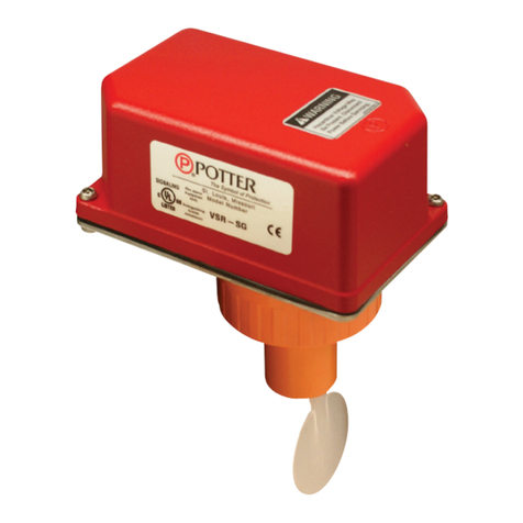
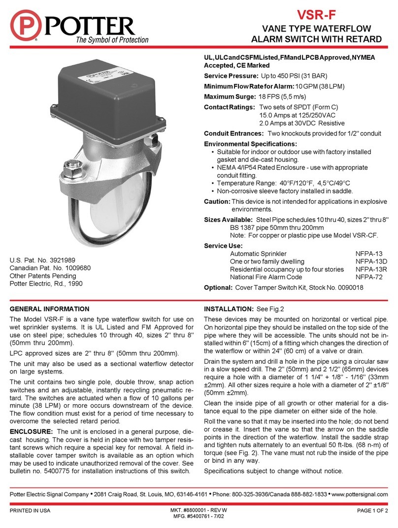
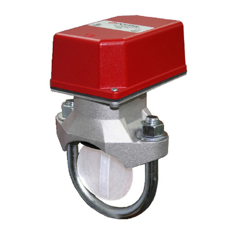
TheModelVSRisavanetypewaterowswitchforuseonwetsprinkler
systems.ItisULListedforuseonasteelpipe;schedules5through40,
sizes2"-6"andisULListedandFMApprovedforuseonsteelpipe;
schedules10through40,sizes2"thru8"(50mmthru200mm).LPC
approvedsizes are 2" thru8"(50 mm thru 200mm).  See Ordering
Information chart.
TheVSRmayalsobeusedasasectionalwaterowdetectoronlarge
systems.TheVSRcontainstwosinglepole,doublethrow,snapaction
switchesandanadjustable,instantlyrecyclingpneumaticretard.The
switchesareactuatedwhenaowof10GPM(38LPM)ormoreoccurs
downstreamofthedevice.Theowconditionmustexistforaperiod
of time necessary to overcome the selected retard period.
Enclosure
TheVSRswitchesandretarddeviceareenclosedinageneralpurpose,
die-cast housing. The cover is held in place with two tamper resistant
screws which require a special key for removal. A eld installable
cover tamper switch is available as an option which may be used
to indicate unauthorized removal of the cover.  See bulletin number
5401103 for installation instructions of this switch.
Important: This document contains important information on the installation and operation of the VSR waterow switches. Please read all
instructionscarefullybeforebeginninginstallation.AcopyofthisdocumentisrequiredbyNFPA72tobemaintainedonsite.
PRINTED IN USA MFG. #5401146 - REV M
11/15
PAGE 2 OF 4
VSR
VANE TYPE WATERFLOW
ALARM SWITCH WITH RETARD
Installation (see Fig. 1)
Thesedevicesmaybemountedonhorizontalorverticalpipe.Onhorizontalpipetheyshallbeinstalledonthetopsideofthepipewherethey
willbeaccessible.Thedeviceshouldnotbeinstalledwithin6"(15cm)ofattingwhichchangesthedirectionofthewateroworwithin24"
(60cm)ofavalveordrain.
NOTE:Donotleavecoveroffforanextendedperiodoftime.
Drain the system and drill a hole in the pipe using a hole saw in a slow speed drill (see Fig. 1). Clean the inside pipe of all growth or other
material for a distance equal to the pipe diameter on either side of the hole. Roll the vane so that it may be inserted into the hole; do not bend
orcreaseit.Insertthevanesothatthearrowonthesaddlepointsinthedirectionofthewaterow.Takecarenottodamagethenon-corrosive
bushinginthesaddle.Thebushingshouldtinsidetheholeinthepipe.Installthesaddlestrapandtightennutsalternatelytorequiredtorque
(see the chart in Fig. 1). The vane must not rub the inside of the pipe or bind in any way.
ADAPTER
USE (2) 5180162 ADAPTERS AS SHOWN ABOVE
DN50 ONLY
ADAPTER
50mm
20mm ±2mm MAX.
DWG# 1146-1F
Fig. 1
NOTE:ForcopperorplasticpipeuseModelVSR-CF.
Retard Adjustment
The delay can be adjusted by rotating the retard adjustment knob from
0tothemaxsetting(60-90seconds).Thetimedelayshouldbesetat
the minimum required to prevent false alarms
(Flowing water activates
device in one direction only.)
DO NOT LEAVE COVER OFF FOR
AN EXTENDED PERIOD OF TIME
TIGHTENNUTS
ALTERNATELY
MOUNTONPIPESO
ARROWONSADDLE
POINTSINDIRECTION
OF WATERFLOW
ROLLPADDLEIN
OPPOSITEDIRECTION
OF WATERFLOW
DIRECTIONOF
WATERFLOW
Hole must be drilled perpendicular to the pipe and vertically centered.
RefertotheCompatiblePipe/InstallationRequirementschartforsize.
Correct Incorrect
Compatible Pipe/ Installation Requirements
Model NominalPipe
Size
NominalPipe
O.D.
Pipe Wall Thickness HoleSize U-BoltNuts
Torque
Lightwall Schedule 10 (UL) Schedule 40 (UL) BS-1387(LPC) DN(VDS)
inch mm inch mm inch mm inch mm inch mm inch mm inch mm inch mm ft-lb n-m
VSR-2 2 DN50 2.375 60.3 .065 1.651 0.109 2.77 0.154 3.91 0.142 3.6 0.091 2.3
1.25 + .125/-
.062 33.0 ± 2.0
20 27
VSR-2 1/2 2.5 - 2.875 73.0 .084 2.134 0.120 3.05 0.203 5.16 - - - -
VSR-2 1/2 - DN65 3.000 76.1 - - - - - - 0.142 3.6 0.102 2.6
VSR-3 3 DN80 3.500 88.9 .083 2.108 0.120 3.05 0.216 5.49 0.157 4.0 0.114 2.9
2.00 ± .125 50.8 ± 2.0
VSR-3 1/2 3.5 - 4.000 101.6 - - 0.120 3.05 0.226 5.74 - - - -
VSR-4 4 DN100 4.500 114.3 .084 2.134 0.120 3.05 0.237 6.02 0.177 4.5 0.126 3.2
VSR-5 5 - 5.563 141.3 - - 0.134 3.40 0.258 6.55 - - - -
VSR-6 6 DN150 6.625 168.3 .115 2.921 0.134 3.40 0.280 7.11 0.197 5.0 0.157 4.0
VSR-8 8 DN200 8.625 219.1 - - 0.148 3.76 0.322 8.18 0.248 6.3 0.177 4.5
Do not trim the paddle. Failure to follow these instructions may prevent the device from operating and will void the warranty. Do not obstruct or otherwise prevent
thetripstemoftheowswitchfrommovingwhenwaterowsasthiscoulddamagetheowswitchandpreventanalarm.Ifanalarmisnotdesired,aqualied
technician should disable the alarm system.
PRINTED IN USA PAGE 3 OF 4
VSR
VANE TYPE WATERFLOW
ALARM SWITCH WITH RETARD
MFG. #5401146 - REV M
11/15
Toremoveknockouts:Placescrewdriverat
insideedgeofknockouts,notinthecenter.
DWG 1146-4
Fig. 2
Do not drill into the base as this creates
metal shavings which can create
electricalhazardsanddamagethe
device. Drilling voids the warranty.
Fig. 4 Switch Terminal Connections Clamping
Plate Terminal
Fig. 3
Break out thin section of cover when
wiring both switches from one conduit
entrance.
Testing
The frequency of inspection and testing for the Model VSR and its associated protective monitoring system shall be in accordance with applicable
NFPACodesandStandardsand/ortheauthorityhavingjurisdiction(manufacturerrecommendsquarterlyormorefrequently).
Ifprovided,theinspector’stestvalveshallalwaysbeusedfortestpurposes.Iftherearenoprovisionsfortestingtheoperationoftheowdetection
deviceonthesystem,applicationoftheVSRisnotrecommendedoradvisable.
Aminimumowof10GPM(38LPM)isrequiredtoactivatethisdevice.
Advise the person responsible for testing of the fire protection system that this system must be tested in accordance
with the testing instructions.
Fig. 6 Mounting Dimensions
DWG. 1146-14
3.50 in
(89.0mm)
2.34 in
(59.4mm)
PIPE DIA.
+ 5.25 in
(+ 133.4 mm)
5.56in
(141.2 mm)
2.00 in
(50.8 mm)
U-BOLTNUT
U-BOLT WASHER
PIPE SADDLE
PIPE
PLASTIC PADDLE
U-BOLT NOMINALPIPEDIA.+1.75in(+44.5MM)FORDN50–DN652–2.5in
NOMINALPIPEDIA.+2.125in(+54.0MM)FORDN80–DN2003–8in
DWG 1146-15
GREENGROUND
SCREWS
Fig. 7
An uninsulated section of a single conductor should not be looped
around the terminal and serve as two separate connections. The
wiremustbesevered,therebyprovidingsupervisionofthe
connection in the event that the wire become dislodged from under
the terminal. Failure to sever the wire may render the device
inoperable risking severe property damage and loss of life.
Donotstripwirebeyond3/8"oflengthorexposeanuninsulated
conductor beyond the edge of the terminal block. When using
strandedwire,captureallstrandsundertheclampingplate.
Notes:
1. TheModelVSRhastwoswitches,onecanbeusedtooperateacentral
station,proprietaryorremotesignalingunit,whiletheothercontact
is used to operate a local audible or visual annunciator.
2. Forsupervisedcircuits,see“SwitchTerminalConnections”
drawing and warning note (Fig. 4).
Fig. 5 Typical Electrical Connections
LOAD TO BELL
NEUTRAL FROM BELL
CONNECTOR
EOL (End Of Line Resistor)
BELL
NEUTRAL FROM
BREAKER
BREAKER
LINE FROM BREAKER
NOTE:
When connecting to a UL Listed
control panel, use the panel’s
resistor value for circuit supervision.
PRINTED IN USA MFG. #5401146 - REV M
11/15
PAGE 4 OF 4
VSR
VANE TYPE WATERFLOW
ALARM SWITCH WITH RETARD
Removal of Waterow Switch
• Topreventaccidentalwaterdamage,allcontrolvalvesshouldbeshuttightandthesystemcompletelydrainedbeforewaterowdetectorsare
removed or replaced.
•Turnoffelectricalpowertothedetector,thendisconnectwiring.        
•LoosennutsandremoveU-bolts.           
•Gentlyliftthesaddlefarenoughtogetyourngersunderit.Withyourngers,rollthevanesoitwilltthroughtheholewhilecontinuing
toliftthewaterowdetectorsaddle.           
•Liftdetectorclearofpipe.
Fig. 8
Retard/Switch Assembly Replacement (See Fig. 8)
 TheRetard/SwitchAssemblyiseld-replaceablewithoutdrainingthesystemorremovingthewaterowswitchfromthe
pipe
1. Makesuretherealarmzoneorcircuitconnectedtothewaterowswitchisbypassedorotherwisetakenoutofservice.
2. Disconnect the power source for local bell (if applicable).
3. Identifyandremoveallwiresfromthewaterowswitch.
4. Remove the (2) mounting screws holding retard/switch assembly to the base. Do not remove the (2) retard housing screws.
5. Remove the retard assembly by lifting it straight up over the tripstem.
6. Installthenewretardassembly.Makesurethelocatingpinsontheretard/switchassemblytintothelocatingpinbossesonthebase.
7. Re-install the (2) original mounting screws.
8. Reconnectallwires.Performaowtestandplacethesystembackinservice.
Maintenance
Inspectdetectors monthly. Ifleaks arefound, replacethe detector. TheVSRwaterow switchshould provideyears oftrouble-free service.
Theretardandswitchassemblyareeasilyeldreplaceable.Intheunlikelyeventthateithercomponentdoesnotperformproperly,pleaseorder
replacementretardswitchassemblystock#1029030(seeFig.8).Thereisnomaintenancerequired,onlyperiodictestingandinspection.
DWG# 1146-10
BREAKOUTTHINSECTIONOFCOVER
WHEN WIRING BOTH SWITCHES
FROMONECONDUITENTRANCE.
DO NOT REMOVE
(2)RETARDHOUSING
SCREWS
REMOVE(2)ORIGINALMOUNTING
SCREWSHOLDINGRETARD/SWITCH
ASSEMBLYTOBASE
RETARD/SWITCHASSEMBLY
(2)ORIGINALMOUNTING
SCREWS
(2)LOCATINGPINS
(2)LOCATINGPIN
BOSSESINBASE
BASE
Mouser Electronics
Authorized Distributor
Click to View Pricing, Inventory, Delivery & Lifecycle Information:
AMSECO:
VSR-4

This manual suits for next models

7

Other Potter Switch manuals

Potter PS120 Series User manual

Potter

Potter PS120 Series User manual

Potter PS10 Series User manual

Potter

Potter PS10 Series User manual

Potter RBVS User manual

Potter

Potter RBVS User manual

Potter PS10 Series User manual

Potter

Potter PS10 Series User manual

Potter PAD100-DRTS User manual

Potter

Potter PAD100-DRTS User manual

Potter VSR-AT Series User manual

Potter

Potter VSR-AT Series User manual

Potter VSR-SG User manual

Potter

Potter VSR-SG User manual

Potter PS40 SERIES User manual

Potter

Potter PS40 SERIES User manual

Potter PS40 SERIES User manual

Potter

Potter PS40 SERIES User manual

Potter CoilKeeper CSS User manual

Potter

Potter CoilKeeper CSS User manual

Potter VSR-F User manual

Potter

Potter VSR-F User manual

Potter PS100-2 User manual

Potter

Potter PS100-2 User manual

Potter VSR-F User manual

Potter

Potter VSR-F User manual

Potter ADPS-300-2S User manual

Potter

Potter ADPS-300-2S User manual

Popular Switch manuals by other brands

Master View CS-1004 user manual

Master View

Master View CS-1004 user manual

Nexxt ASFRM244U2 user guide

Nexxt

Nexxt ASFRM244U2 user guide

HB Products HBSC2-SSR quick start guide

HB Products

HB Products HBSC2-SSR quick start guide

schmersal TESZ operating instructions

schmersal

schmersal TESZ operating instructions

Juniper EX4100 Hardware guide

Juniper

Juniper EX4100 Hardware guide

TRENDnet TK-217i Specifications

TRENDnet

TRENDnet TK-217i Specifications

Leviton 47611-5GB Product specifications

Leviton

Leviton 47611-5GB Product specifications

Erreka SL01 installation instructions

Erreka

Erreka SL01 installation instructions

NETGEAR 7200 Series Quick installation guide

NETGEAR

NETGEAR 7200 Series Quick installation guide

Cisco SD208P quick start guide

Cisco

Cisco SD208P quick start guide

Gira 0615 00 installation instructions

Gira

Gira 0615 00 installation instructions

Lindy 43228 user manual

Lindy

Lindy 43228 user manual

Heltun QUINTO HE-RS01 user manual

Heltun

Heltun QUINTO HE-RS01 user manual

Lantech IPES-0104GT-4 user manual

Lantech

Lantech IPES-0104GT-4 user manual

Avaya VSP 7200 Series Installing manual

Avaya

Avaya VSP 7200 Series Installing manual

CYP CPLUS-V3H1H-TB Operation manual

CYP

CYP CPLUS-V3H1H-TB Operation manual

J.Burrows JBUSBHD015 instruction manual

J.Burrows

J.Burrows JBUSBHD015 instruction manual

Cisco Catalyst 2960 Series Command reference guide

Cisco

Cisco Catalyst 2960 Series Command reference guide

manuals.online logo
manuals.online logoBrands
  • About & Mission
  • Contact us
  • Privacy Policy
  • Terms and Conditions

Copyright 2025 Manuals.Online. All Rights Reserved.