Potter VSR-SG User manual

PRINTED IN USA PAGE 1 OF 4MFG. #5401205 - REV H
01/12
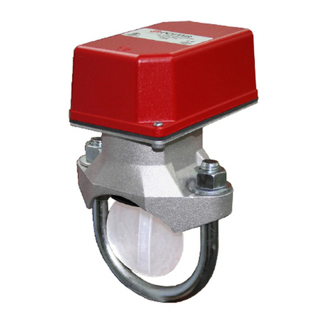
VSR-SG
VANE TYPE WATERFLOW
ALARM SWITCH WITH RETARD
AND GLUE-IN UNION
FOR CPVC PIPE
Do not over-tighten the union nut, hand tighten only. Use of a wrench
may damage the union nut.
Do not trim the paddle. Failure to follow these instructions may prevent the
switch from operating and will void the warranty.
General Information
period of time necessary to overcome the selected retard period.
UL, CUL and CSFM Listed, CE Marked
Service Pressure:
Flow Sensitivity Range for Signal:
Maximum Surge:
Contact Ratings:
10.0 Amps at 125/250VAC
10 mAmps min. at 24VDC
Conduit Entrances: Two openings provided for 1/2" conduit.
for dissimilar voltages.
Environmental Specications:
outdoor use with factory installed gasket and die-cast housing
Service Use:
National Fire Alarm Code NFPA-72
accordance with all national and local codes and ordinances.
injury or death could result.
Stock Number: 1144460
Optional
Replaceable Components:
Enclosure
The VSR-SG switches and retard switch are enclosed in a general
purpose, die-cast housing. The cover is held in place with two tamper
trapped air, or short retard times.
www.pottersignal.com
Installation (
for gluing into a CPVC plastic tee.
NOTE:
TEE
for instructions on how to change paddle. Verify that the o-ring is
properly positioned in its groove. Hand tighten the nut on the union
as shown in Fig. 5 & Fig. 7.
PRINTED IN USA MFG. #5401205 - REV H
01/12
PAGE 2 OF 4
VSR-SG
VANE TYPE WATERFLOW
ALARM SWITCH WITH RETARD
AND GLUE-IN UNION
FOR CPVC PIPE
Notes:
central station, proprietary or remote signaling unit, while the other
Fig. 4 Typical Electrical Connections
conduit entrance.
Testing
Fig. 2
Important:
11 paddles are furnished with each unit
manufacturers of TEES. The paddles have
raised lettering that show the pipe size and
the TEE manufacturer they are to be used
with. The proper paddle must be used. The
securely tightened.
Fig. 1
preparation and gluing of CPVC piping
systems. Wait 2 to 4 hours to allow the glue
Fig. 3
DWG# 1205-4
with the testing instructions.
LOAD TO BELL
NEUTRAL FROM BELL
CONNECTOR
EOL (End Of Line Resistor)
BELL
NEUTRAL FROM BREAKER
BREAKER
LINE FROM BREAKER
NOTE:
When connecting to a UL Listed
control panel, use the panel’s
resistor value for circuit supervision.

PRINTED IN USA MFG. #5401205 - REV H
01/12
VSR-SG
VANE TYPE WATERFLOW
ALARM SWITCH WITH RETARD
AND GLUE-IN UNION
FOR CPVC PIPE
Fig. 6 Switch Terminal Connections Clamping Plate Terminal
Fig. 5
Fig. 7 Mounting Dimensions-Orientation
GREEN GROUND
SCREWS
Fig. 8
Retard Adjustment
DWG# 1205-1A
RETARD
ADJUSTMENT
MOUNT SO ARROW ON
Do not leave cover off for extended period of time
RUN OF THE TEE
Flowing water activates switch in one
direction only.
DWG# 1205-15
DWG# 1190-1
5.56 in
PIPE
2.00 in
terminal and serve as two separate connections.
When using stranded wire, capture all
strands under the clamping plate.
PIPE
90°
perpendicular with the pipe. Improper orientation could delay or prevent

PRINTED IN USA MFG. #5401205 - REV H
01/12
PAGE 4 OF 4
VSR-SG
VANE TYPE WATERFLOW
ALARM SWITCH WITH RETARD
AND GLUE-IN UNION
Removal of Waterow Switch
•
removed or replaced.
FOR CPVC PIPE
Fig. 9
Retard/Switch Assembly Replacement
pipe
1.
2.
4. Do not
5.
6.
7.
Maintenance
and inspection.
DWG# 1190-2
FROM ONE CONDUIT ENTRANCE.
DO NOT REMOVE
SCREWS
SCREWS
Table of contents
Other Potter Switch manuals

Potter
Potter VSR-AT Series User manual

Potter
Potter VSR-F User manual

Potter
Potter RBVS User manual

Potter
Potter PS10 Series User manual

Potter
Potter VSR-2 User manual

Potter
Potter PS100-2 User manual

Potter
Potter CoilKeeper CSS User manual

Potter
Potter PS40 SERIES User manual

Potter
Potter VSR-F User manual

Potter
Potter PAD100-DRTS User manual