Listing/Approvals: UL Standard 508 Guide
(NKPZ) and CSA Standard C22.2 No. 14-
M Class (321106) for Pressure Operated
Industrial Control Equipment.
UL Standard 873 Guide (XAPX) and CSA
Standard C22.2 No. 24 Class (481302) for
Temperature Indicating and Regulating
Equipment.
CE Marked
Ambient/Media Temperature Range:
-4°F to 180°F (-20°C to 82°C)
Construction:
• NEMA Type 4X Enclosure for indoor or
outdoor use. (To maintain 4X rating, use
appropriate Type 4 conduit hub.)
• Forged Brass or 316 S.S. Pressure Con-
nections
• Aluminum Diecast Base with Polymer En-
closure
• Beryllium Copper Diaphragm (Stainless
steel isolator diaphragm included for pro-
tection of beryllium copper diaphragm on
models with stainless steel pressure con-
nection.)
• Nitrile Pressure Sealing O-ring
Switch Contact:
Snap-Action SPDT (Form C)
15 Amps at 125/250/480 VAC
1/8 HP at 125 VAC
1/4 HP at 250 VAC
CAUTION: Direct control of motors with HP
ratings greater than the ratings shown
could result in premature failure of the
ADPS or significantly shortened operat-
ing life.
GENERALDESCRIPTION
The model ADPS is an Adjustable Deadband
Pressure Switch with independent set and re-
set points which are adjustable throughout the
entire operating range of the switch. The mini-
mum deadband (minimum span between set
and reset points) may be obtained at any point
in the operating range of the switch. A change
in pressure greater than the high setting will
reposition the switch mechanism to open or
close a single snap-action electrical switch.
This control device is designed for use as an
operating control in applications sensing air,
Potter Electric Signal Company • 2081 Craig Road, St. Louis, MO, 63146-4161 • Phone: 800-325-3936/Canada 888-882-1833 • www.pottersignal.com
water, or any fluid not harmful to the pressure
connection, diaphragm or nitrile pressure-seal-
ing o-ring. Where an operating control would
result in personal injury and/or loss of property,
it is the responsibility of the installer to add
devices (safety, limit controls) that protect
against, or systems (alarm, supervisory sys-
tems) that warn of control failure.
This device is not intended for applications in
explosive environments or use with hazardous
fluids.
PAGE 1 OF 4PRINTED IN USA MFG. #5401060 - REV H
5/02
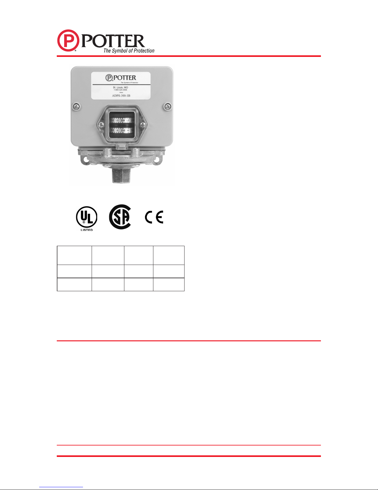
ADPS
ADJUSTABLE DEADBAND
PRESSURE SWITCH
ELBATSUJDA GNITAREPO EGNAR
MUMINIM DNABDAED FOORP ERUSSERP YROTCAF GNITTES
GISP003-52GISP21GISP004GISP06/09
GISP006-05GISP52GISP056GISP002/003
See Model Options on page 4.


