Powabyke X-6 LS User manual

• Powabyke X-6 LS
• Powabyke X-6
• Powabyke X-24
Owners Guide &
Assembly Instructions
Please Read Carefully Before Riding
www.powabyke.com

2
Pre-Delivery Inspection (PDI)
• BATTERY & CHARGER UNIT
1. The battery is a sealed unit and the casing should be checked to ensure it
is free from physical defect or damage.
2. The battery fuse holder should be checked to ensure that a correctly rated
(20AMP) fuse is present and working.
3. The key lock should be checked to ensure the correct key, barrel
movement, locking position and key removal can be obtained.
4. Examine and check that the charger unit is free from physical defect and
damage and is fitted with a U.K. plug and a 13amp fuse.
5. Ensure that charging begins and that the charger LED turns red. Place a
known fully charged battery on the bike and ensure the charger unit turns
yellow/green within a few minutes.
• BRAKES
6. The brake levers should be checked to ensure free movement and return
along with the correct seating of brake cable within the lever.
7. Brake cables should be checked to ensure free movement to the calliper,
that they are free from damage and that the cable locking nut on the
calliper is secure. Any excess cable should be tied or cut to a sensible
length and capped.
8. Locate and check brake blocks, ensure that they are correctly positioned to
make contact with the wheel rim and that the retaining nuts are secure.
9. Ensure that the front and rear brake callipers are correctly centred and
that the movement is smooth and effective in gripping the wheel rims.
• BRAKE & ELECTRIC CABLES
10. Check to ensure that all cables are correctly routed, free from chaffing or
snagging and cable tied to the frame or handlebars as appropriate.
• CHAIN, CHAIN GUARD & SPROCKET
11. Check to ensure that the chain is correctly tensioned between the front
and rear sprockets and free from physical defect.
12. Where a speed gear sprocket is fitted. Ensure that the chain and gear
selector assembly moves freely and correctly through the gear selections
and that the gear selection mechanism is securely fixed to the handlebars.
13. Check to ensure that the chain guard is free from physical defect or
damage, that the guard is correctly positioned and that the retaining nuts
are secure.
• ELECTRIC MOTOR
14. The front hub motor should not need any specific examination, however
upon completion of all checks and assembly of the bike, the motor should
be tested as part of the final road test.
15. All electric connectors and retaining nuts on the assembly and cable feeds
should be checked to ensure that they are free from physical defect or
damage and that they are correctly positioned and tight.
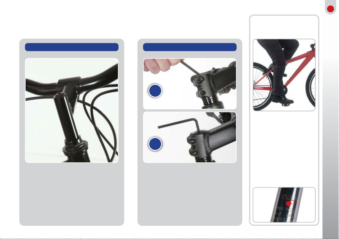
PACKAGING
Powabykes are well packaged to prevent transport damage. Typically a bike
will be delivered in three master cartons, bike frame, front motor wheel
and battery. During transport a number of items are removed from the bike
e.g. The seat, front wheel, mudguards, handlebars, pedals and battery.
IMPORTANT SAFETY NOTICE
It is imperative that your new Powabyke or Powatryke is assembled and
adjusted for use by a qualified & authorised Powabyke dealer only. Failure to
comply with this stipulation may put your safety at risk and void the warranty.
Please consult with your dealer to ensure you have an adequate & legal
lighting system for your bike, and we would strongly recommend that you wear
a bicycle helmet. Finally, remember to post your warranty card to Powabyke.
The following items form part of the PDI procedure.
This must be carried out by the supplying dealer.

3
Contents
Mechanic’s signature:
Customer’s signature:
Date:
• FRAME
16. The frame should be carefully examined to ensure it is
free from damage or defect.
17. All frame joints and frame mounted bearings should
be inspected to ensure that they are free from
physical defect or damage and operate smoothly.
• HANDLEBARS
18. The stem will be loose, the handlebars will have
turned level with the frame for the purposes of
transport. The handlebars should therefore be
straighten to the correct position and the stem
tightened.
19. The handlebars should be examined to check that
they are free from physical defect or damage.
20. Both brake levers should be checked to ensure they
are free from physical defect or damage, that the
retaining nut is tight and that they are correctly
positioned.
21. Check that the mudguards are firmly attached to the
bodywork and that all supports are in place and tight.
22. The pedals (left & right specific) are removed during
transit, therefore they need to be located and
secured to the pedal arms of the bike.
• REFLECTORS
23. Check to ensure that reflectors are both present and
securely fastened to the front and rear wheels, at the
front of the bike extending from the handlebar stem
and at the rear of the bike on the mudguard.
• SADDLE & STAND
24. The saddle is sprung loaded and should be securely
fixed to the frame. The saddle should be checked to
ensure it is free from physical damage or defect.
25. The stand should be checked to ensure that it is free
from physical damage or defect.
26. The spring mechanism should be checked to ensure
that it moves easily and freely and lubricated as
necessary.
• THROTTLE
27. The throttle mechanism should be checked to ensure
it is free from physical damage or defect and that
the assembly is securely fastened to the handlebars.
28. Check to ensure that the throttle control fully opens
and closes smoothly and without jamming.
• WHEELS & TYRES
29. Check to ensure that the tyres are free from physical
damage or defect and that the valves are correctly
seated.
30. Check and inflate tyres to the correct pressure and
ensure that dust caps are present on the valves.
31. Inspect the wheel rims, bearings and spokes for
physical damage or defect and that the wheel nuts,
spoke nuts and bearings are tight.
32. Rotate both the front and rear wheel and ensure it
is free from wobble or buckle and does not foul the
brake blocks.
• THE FINAL ROAD TEST
33. Having performed all of the above tests and checks,
the bike should be road tested to ensure the
following operations;
34. That the throttle opens and closes correctly and the
pick up with the motor is correct and the brakes
efficiently stop the cycle.
4. KNOW YOUR BIKE
QUICK ASSEMBLY GUIDE
11. PERSONAL SAFETY
13. BIKE SERVICE LOG
14. STEERING, HEADSETS
AND HANDLEBARS
16. PEDALS
17. CRANKS
18. SADDLE ADJUSTMENT
20. SUSPENSION
21. BRAKES
24. GEARS
28. MAINTENANCE
33. REGISTRATION FORM

4
Your Powabyke X-Byke is the same as any normal cycle and requires
the same care, maintenance and attention when riding.
In addition your X-Byke has:-
1. A 200 Watt Motor built into its Front Wheel
2. A Twist operation Throttle mounted on the right hand side
of the Handle Bars.
3. Battery Level Lights on the Throttle
4. A Key operated Control Box on the Bracket of the Rear Rack.
5. A Pedal Sensor and disc on the Left Hand Pedal Crank Arm.
6. Removable 36V 6 Amp Lithium Battery Pack located on the
Bottle Holder on the Down Tube in the centre of the bike.
7. A 100VAC – 240VAC 1.5A Charger with output of 42V
8. An Anti-Rotation Bracket on Right Hand Forks
9. Wider Front Forks to accommodate the Motor Hub
a) In Pure Power mode you must rotate the pedals at least 3 COMPLETE
revolutions (Forwards or Backwards) and twist the throttle. Then,
until the bike comes to a complete standstill for at least 5 seconds,
the Motor (by use of the throttle) will power the bike whether you are
rotating the pedals or not. The throttle controls the output from the
motor. The motor will cut out at the pre-set limit of 15mph. The rider
can pedal the bike at any time whilst them motor is in operation using
the gears as appropriate. During the 5 seconds when the bike comes
to a standstill there will be a small “Pulsing” allowing pull away without
again pedaling.
b) If you choose Pedal Assist mode the motor (by use of the throttle) will
assist you only while the pedals are rotating. The throttle controls the
power output from the motor. The motor will cut out at the pre-set limit
of 15mph. The rider can pedal the bike at any time whilst them motor is
in operation using the gears as appropriate.
Battery Care & Charging Guide
a) Your Lithium Battery does not suffer from “Memory Effect” so the
amount you charge it or regularity with which you charge it will not
affect its “Long Term” life.
b) Unlike other types of Battery, your Lithium Battery can be left
“Uncharged” for several months with no affect on its “Long Term” life.
c) Storage temperature Parameters -20C to +45C
d) Charging - Please follow the instructions on the charger for status of
charging - as a guide the Battery will be 80% charged in the first 4 hours.
The remaining 20% may take a further 4 hours. (To turn the Charger light
to Green)
e) With all Electrical equipment it is best to turn off when complete but
you can leave the charger “Charging” as it will cut off automatically.
f) Please do not attempt to open your Battery Pack, your dealer must do
servicing and fault finding.
g) Do not dispose of your battery other than through your dealer. In no
circumstances attempt to burn your Battery.
Power System Instructions
The rider has two choices of power system:
a) First Ignition Position; Pure Power mode
b) Second Ignition Position; Pedal Assist mode
Choose which function you want using the ignition key.
Powabyke X Byke Electric Bike
Operation Guide

5
Quick Assembly Guide
IMPORTANT
Please read these instructions carefully.
For more detailed information and tips, including a comprehensive
guide to care and maintenance we recommend you read the owners
guide in detail.
Powabyke bikes are fully adjusted and checked over at the factory.
The handlebars may be removed or assembled in the bike and turned
through 90 degrees. The pedals will be removed and in some cases the
front wheel will have been removed too. It is a relatively simple operation
to re-assemble these parts, however if you do not feel competent to do
this you should ask someone who is, as it is important that these simple
tasks are done correctly for the integral safety of the bike. If in doubt
consult a qualified mechanic or cycle dealer.
IMPORTANT - Know Your Bike
Check that you use your bike correctly.
There are different European
Standards for bicycles depending
on how the bicycle is intended to
be used.
You can check the table below what
type of riding your bicycle has been
designed for.
Note: To find the correct BS:EN
standard for your bicycle please
refer to the label on the frame
orrectly.
Unpacking
Please remove all packaging very carefully, especially if using a knife or
sharp blade. Take care not to scratch any of the parts of the bike or slash
the tyres.
We suggest that you keep hold of the carton in case you need to return
the bike.
Supplied With Your Bike*
• Allen key (s)*• Pedals
• Multi-spanner*• Reflectors
*Where applicable
For detailed adjustment and other information
please refer to the specific sections in this guide
Type of use for
which bike is
designed
Permissible total
weight of rider +
luggage
BS: EN 14764
Trekking Bikes
BS: EN 14766
Mountain Bikes
BS: EN 14781
Racing Bikes
Riding on roads and
tracks. Not for off road
or rough terrain
Off road, rough
terrain, cycle tracks
or road
High Speed amateur
use on public roads
Not for off road or
rough terrain.
120 Kg (19 stone)
120 Kg (19 stone)
120 Kg (19 stone)

6
Safety Points
This sign is used in this booklet, wherever a
particular topic is safety sensitive or needs extra
care. Some of these items are specified in the
British Standard covering bicycles but many
others are Powabyke recommendations.
Preparing your bike for assembly
1. Chain wheel set
2. Front gear mechanism
3. Rear gear mechanism
4. Handlebar stem
5. Seat post
6. Multiple sprockets
7. Top tube
8. Seat tube
9. Down tube
10. V-style brake
11. Chain set axle bolt
12. Hub motor
4
FRAME NO.
5
7
4
10
12
11
1
2
10
3
6
FRAME NO.
12
10
1
11
9
2
8
10
5
3
6
Right hand
chainwheel
side
900

7
Attaching the handlebars
There are two types of handlebar attachment in general use, the stem type (single bolt) and the threadless or
A-Head type (two bolts).
1Remove the plastic cap (if present) from the
top of the handlebar stem cap and loosen the
bolt using the 6mm allen key.
2 Turn the handlebar and set at 90 degrees to
the front wheel. Set at the required height and
re-tighten the bolt.
Important: Do not position the stem outside
the limit mark.
Stem Type (Single Bolt)
To adjust the saddle height,
loosen the clamp bolt using an
Allen key, spanner or the quick
release lever and adjust the seat
post to the required height.
Adjust the height of the saddle
so that when cycling along, your
leg will be slightly bent with the
pedal at its lowest point.
Important: When altering the
height of the saddle, you must
not pull the seat post out
further than the limit mark.
Saddle
Adjustment
1Using an allen key, loosen the 2 sides bolts
(A) followed by top bolt (B) and turn the
handlebar through 90 degrees.
2Re-tighten all bolts fully so there is no
movement whatsoever and the handlebars are
securely fixed.
Threadless Type (3 Bolts)
B
A

8
Undo the motor wires Undo Anti-rotation bracket
Front Wheel
In order to fit the front wheel
it will be necessary to unhook
the brake pipe ferrule from the
brake arm bracket.
Replacing the front wheel motor
Unhooking the
brake pipe
Re-linking the brake:
1Squeeze the brake arms inward
in the direction of the arrows.
2Locate the ferrule on the
brake pipe in the cut out of the
bracket.
3 Apply the right-hand brake
lever to check for smooth
efficient operation of the brake.
Models with
Disc Brakes
It is better if the bike is upside
down when fitting a disc brake
wheel.
Disc brakes use 2 pads and these
are usually kept in place with
packing pieces during transit.
Remove the packaging from
between the disc pads making
sure that the pads are not
displaced.
Fit the wheel in place with the
rotor plate between the 2 pads.
Follow previous instructions for
tightening quick release and
wheel nuts.
CHECK THE BRAKES ARE
CORRECTLY LINKED
RH LEVER > FRONT BRAKE
LH LEVER > REAR BRAKE
IMPORTANT
Important: Ensure the nuts
are fully tightened.
Left side of the Motor Wheel Unscrew the motor
connection cover
Release “V” Brakes. Loosen the 2 nuts on both sides
of Motor Wheel. (18mm spanner)
Remove wheel.
1 2
3 4
5 6

9
1Identify left and right pedals by
the letter R & L stamped on the
end of the thread.
2Identify left and right cranks.
Tighten pedal by hand into the
correct crank. Note the correct
rotation.
3Tighten the pedals by hand,
then using a spanner fully
tighten in the correct rotation.
Remember
• Correct pedal and crank
• Correct tightening rotation
• Do not cross-thread
• Always keep pedals tight
• Check and retighten regularly
Pedals
For safety reasons it is very important that these are fitted correctly
as the photograph below. Depending on the type supplied, the front
reflector may be fitted to the handlebar or fork and the rear fitted to
the seat post or rear bridge (see photos below).
Before you ride check the following:
1. Tyres are inflated to the recommended pressure.
2. Brakes are functioning properly.
3. Axle nuts or quick release levers are tightened.
4. Handlebar bolt(s) is tightened.
5. Seat bolt is tightened.
KEEP YOUR REFLECTORS CLEAN -
CYCLISTS MUST BE SEEN .
THE REFLECTORS FITTED TO YOUR NEW BIKE ARE A
LEGAL REQUIREMENT, SUPPLIED FOR YOUR SAFETY.
DON’T BE TEMPTED TO REMOVE THEM.
Important: Be safe!
Ensure pedal is tight up against
the crank when fully tightened
Reflectors

10
Once a helmet has been in an
accident, it-must be replaced. The
shell may have been weakened
and the liner will be less able to
absorb shocks. Remember that
some manufacturers offer free
replacement of crash-damaged
helmets.
When riding in the dark, it’s a legal
requirement to fit and use a front
and rear light marked to show
that they conform to the British
Standard BS 6102/2. Clean the
lenses and reflectors every week
or so to keep them fully effective.
Take out the screws in the fork ends. Using these screws, loosely
fit the stays to the fork ends. Fit the mudguard bracket behind
the fork. Ensure all screws are tightened.
Fitting for suspension forks.
PERSONAL
SAFETY
HELMETS
There’s no doubt that a certain amount
of equipment can improve cycling
safety, particularly at night. On the
other hand, however much equipment
you have, there’s no substitute for
cycling skills and a full awareness of
other traffic.
When you buy a cycle helmet,
it’s important to check that it’s
manufactured to a proper standard.
The minimum legal requirement
for any helmet sold in the UK and
the rest of Europe is that they are
CE certified and conform to the
EN1078:1997 European Standard.
LIGHTS
As for lights, you must have a front and
rear light marked to show that they
comply with British Standard. Legally,
you must not fit a flashing light to a
bike, though you can fit one to your
clothing if you wish to. Only a few LED
lights produce enough light to comply
with the British Standard, even when
they’re in the non-flashing mode. This
means they can only be used as a
supplement to British Standard lights
and mustn’t be used on their own. If
you find yourself fitting new batteries
too often, consider fitting rechargeable
lights or a dynamo. Your Powabyke
Dealer will advise.
Front Mudguard (Where Applicable)

11
When buying a helmet, try out
several different styles and
different sizes within each style
as well. Select one that feels
comfortable and secure, that fits
well down on your forehead and
which has straps that lie well away
from your ears.
Once you’ve got a good fit,
adjust the straps carefully,
making sure that the adjusters
sit well below the ears and don’t
get twisted. Many helmets also
have an adjustable nape strap at
the back of the helmet. Follow
manufacturers’ instructions.
To get a good fit, helmets have
either an exterior adjuster, simple
pads or inflatable side pieces.
Once adjusted, hold the helmet
upside down with the straps out
of the way to make it easier to
put on. Follow manufacturers’
instructions.
Check frequently that your lights
are as bright as they should be.
The batteries in particular need
changing frequently, so keep
spares at home and at work.
When replacing bulbs, especially
halogen ones, don’t touch the
glass at all.
You can also fit reflective material
to the bike itself. Large areas are
best but even small strips make
you more visible. It’ll stick better if
you clean any grease or oil off the
frame before fitting. Try to blend
the reflective areas in with the
shape of the bike.
Good lighting should be backed
up by other visibility aids. If a bright
yellow reflective jersey is too
much for you, wear a reflective
belt, preferably one that goes
round waist and shoulders.
They’re very effective at letting
motorists know you’re on the road.
LED bike lights usually have a
clip so you can attach them to
your clothing. There is also a
switch to select a steady or a
flashing light. They should only
be fitted as a back-up to a legal
light, or to a dynamo.
Most LED lights have a close-
fitting plastic case. To fit new
batteries, find the notch in the
case and prise the two halves
apart with a screwdriver. There is
no bulb as such. When putting
the case back together, take
care to avoid damaging or
moving the rubber seal.
g, y
Good lighting sho
Y
ou
ld
be
bac
ked
ould
LED Rear Lights

12
WARNING: There is a risk of injury to the rider and to others if all
necessary repairs and adjustments are not made. Take every precaution
to ensure safe riding.
• BEFORE RIDING
Carry out the checks listed on page 3 and also refer to ‘Know your bike’
section so that you understand the type of use your bike is designed for. If
you have any problems refer them to your Powabyke Dealer at once.
Make sure you are able to use your gears and brakes effectively and that
you can handle your bicycle safely in traffic. To-familiarise yourself with the
many rules of the road, Powabyke recommend you obtain a current copy of
the Highway Code, available from Post Offices and most good bookshops.
All new or inexperienced cyclists are strongly recommended to take a
training course in cycling. Details may be obtained from council offices or
Police stations.
• ANTICIPATION
The most important general riding skills you need to develop are keeping
track of what other road users are doing and working out what they are
going to do next. That way you can position yourself safely on the road and
let them know, by your road position, what you are going to do next. Do
not follow too closely behind other road vehicles or other cyclists and avoid
riding up the inside of traffic queues. Make use of “cycle lanes” where they
are provided. Always concentrate and keep a good grip on the handlebars
at all time in case you suddenly need to steer out of harms way.
• RIDING IN BAD WEATHER
Always take extra care when the weather is wet, foggy, windy or icy. Wear
warm waterproof clothing - in bright, reflective colours if possible. Ride
slowly and brake early, as stopping distances can be doubled or trebled.
Sudden braking could lead to skidding on hazards such as mud, gravel,
snow, etc. When it’s like that don’t just rely on hearing other traffic because
snow, wind and fog can carry away the sound of approaching vehicles.
When conditions are really bad or an area is particularly congested be
prepared to walk your bike around roundabouts and difficult right turns.
Bicycle travelling at approx 15 mph
STOP
STOP
IN DRY WEATHER
THINKING DISTANCE
4.5m
STOPPING DISTANCE
5.5m
THINKING DISTANCE
4.5m
STOPPING DISTANCE
11.5m
IN WET WEATHER
• RIDING IN THE DARK
Again, take extra care in the dark. Make sure your signals are in good time,
so motorists are aware of your intentions.
Make sure you can see and be seen - front and rear lights, a rear reflector,
pedal and wheel reflectors are legal requirements. They should conform to
British Standard BS 6102. Carry spare bulbs and batteries if needed. Light
coloured and reflective clothing will help you to be seen - ask to see the
range stocked by your Powabyke Dealer.
• PERSONAL MUSIC PLAYERS/HEADPHONES
We recommend that YOU DO NOT LISTEN to such devices while riding.
They distract your attention from the traffic around you and prevent you
from hearing approaching danger.
• AFTER YOUR FIRST FEW RIDES
All the nuts and bolts on your bicycle bed-down in the first few weeks of
use, we recommend you regularly check your bike as per the maintenance
section.
Riding Advice
SAFE BRAKING DISTANCES

13
Bike Service Log
Date Dealer Name Information/Description

14
When you’ve got the saddle height and position right, you can fine tune your
riding position by altering the angle of the handlebars. On some bikes, you can
also adjust the height of the handlebars. Don’t forget that altering the angle of
an adjustable stem also alters the height of the handlebars.
Your back should be roughly 45° to the ground but this is not a hard and fast
rule. It’s also a good thing to have a slight bend at the elbow to help absorb
road shocks. In fact, most mountain bikes are designed to provide the correct
back angle and arm reach for the majority of riders. If you have a problem
getting comfortable, consult your Powabyke Dealer about altering the height
of the handlebars or even fitting different ones. Always check the alignment of
the handlebar stem with the front wheel, if you move anything else.
If there’s any free play in the steering bearings, you’ll get brake judder, judder
over bumps and steering wobble as well. Tight steering may also be a problem.
These are potentially dangerous so if you don’t feel confident about making
the adjustment, take the bike to your Powabyke Dealer.
As part of the Safety Check, make sure the stem clamp
bolts and the handlebar clamp bolts are all tight enough
to prevent the handlebars moving.
To check the steering bearings,
pull the front brake on and
wrap your fingers round the top
steering bearing. Then try to
push the bike gently backwards
and forwards, keeping the back
wheel on the ground. If you can
feel of hear any movement the
headset needs to be
tightened.
While there should be no play
in the steering there should be
no stiffness either. This can be
checked by lifting the front of
the bike so that the wheel is
off the ground and turning the
handlebar with a finger. The
wheel should move smoothly
right and left without sticking.
For adjustment of steering
bearings see the appropriate
section on the next page.
Steering Play -
Too Loose
Steering, Headsets
and Handlebars Steering Play -
Too Tight

15
Threadless headset adjustment
Start by loosening the stem clamp bolts (A) just enough to allow the stem
to turn when pushed but not to swing freely. If the steering is too loose
adjust the bearings by tightening the top screw (B) until you can no longer
feel any movement.
To adjust for tight steering undo the top bolt slightly until the steering
moves freely. You may need to repeat the above process until the
adjustment is correct.
Threaded headset adjustment
First undo the top head locknut (C) using a suitable spanner. To correct
loose steering turn the screwed race clockwise slightly until there is
no play. To relieve tight steering, turn the screwed race (D) anti-
clockwise a little. Once adjusted re-tighten the top head locknut and
test the steering. You may need to repeat the above procedure until the
adjustment is correct.
Height Limit Mark
Some models are fitted with a continental design of stem. Here, you remove the rubber bung at the top to
reveal a socket-headed bolt, then undo the bolt a few turns. Once it’s loose, raise or lower the handlebars by
holding the front wheel between your legs and twisting the handlebars from side to side. Don’t pull it out any
further than the limit mark shown by the arrow in the picture. Next, re-tighten the bolt and fit the rubber bung.
Then, hold the wheel between your legs and check that the handlebars won’t twist in the frame. Check also
that the handlebar clamp is tight. Repeat both these final checks during Safety Check.
A B
C
D

16
Don’t underestimate the
importance of the pedals. If
they’re not tight enough, if the
toe clips are loose, if the toe
straps are missing or if the pedals
don’t turn smoothly, it’s only too
easy to lose control.
ANY PROBLEMS ALONG THE
WAY?
CONSULT YOUR POWABYKE
DEALER.
If the pedals haven’t been fitted or you’ve removed them when storing
the bike, check which side they fit on. One pedal is marked L for the
left hand crank and the other R for the right hand crank. Don’t try to
fit them the wrong way round.
You fit the R pedal onto the crank by turning the spindle clockwise.
But when fitting the L pedal, you turn it anti-clockwise. To finish the
job off or as part of your regular safety check, tighten both pedals with
an open-ended spanner.
Toe clips can be fitted to prevent your foot sliding off the pedal as well
as to hold it in the correct position. That makes them a safety device
as well as a vital part of efficient cycling. It’ll take practice before you
can slip into them automatically.
Checking
Pedals 1
2
3
Torque settings
Powabyke recommend the use
of a torque wrench, whenever
working on your bike. This
will ensure that all nuts and
bolts are tightened using
the correct amount of force,
so preventing damage to
components. See page 31 for
a list of torque settings

17
All the power that you generate with
your legs passes through the chainset
and the bottom bracket bearings,
which means that the hexagon bolts
holding the cranks onto the bottom
bracket must be kept very tight.
Powabyke recommend using a torque
wrench but a long hexagon key will
do. You won’t be able to tighten them
enough with a standard one.
If you ever hear a creaking noise from
the bottom bracket, it may be a sign
that one or other of the crank bolts
need tightening. Don’t ride a bike
with creaking cranks or you’ll damage
them and it’ll be impossible to ever
tighten them properly again. From
time to time, it’s also worth checking
that the bolts holding the chainrings
to the cranks are tight.
To tighten up the crank bolts,
grasp one crank firmly with one
hand to hold the chainset still.
Then apply as much force with
a torque wrench or hexagon key
as you can with the other. Don’t
forget to tighten the other crank
as well.
When you’ve tightened both
crank bolts, check that the thread
of both crank bolt covers is lightly
coated with anti-seize grease. Then
tighten the covers, where fitted,
with a pin spanner so they won’t
come out while you’re riding.
Before you check how tight the
chainring bolts are, it’s worth
undoing each one in turn and
coating the thread with copper-
based anti-seize compound before
refitting. This prevents corrosion
and stops the bolts seizing up.
Check the crank bolts for tightness
by holding one crank absolutely
still while you try to move the
other. Test for movement from
side to side as well as backwards
and forwards. Then apply the test
to the other crank.
To test for wear in the bottom
bracket bearings, take hold of
the ends of both cranks and
try to rock them from side to
side. If only one crank seems
to move, it’s loose on the axle
and the crank bolts should be
tightened up before you ride
the bike again.
On the other hand, if both
cranks move sideways the
same amount, the bottom
bracket bearings have got
some play in them.
Sometimes the bearings can
be adjusted to eliminate this
play but if it’s a modern, sealed
bottom bracket, the whole
thing has to be replaced. In
either case, it’s a job for your
Powabyke Dealer. However,
depending on how much you
use your bike, it’s unlikely to
need doing for several years.
Checking
bottom bracket
Checking
The Cranks 1
2
3
4

18
There’s no hard and fast rule for setting up the riding position on a bike.
The best starting point is to set the saddle height so that you can get the
ball of your foot on the ground while you’re sitting on the saddle.
When you have to raise the saddle, don’t lift it any higher than the limit
mark. There’s a danger that the seat post will break or fall out of the frame
if you do. Fit a longer seat post or buy a bigger bike if you need the
saddle higher than allowed by the limit mark.
There is also a fore-and-aft adjustment but you must only move the saddle
to another position along the parallel section of the saddle wire, marked
by the arrows below. Don’t try to force the saddle any further in either
direction or you’ll break the saddle clip. Be careful also when tightening
the bolt under the saddle or you’ll damage the alloy threads.
Start with the saddle right in the middle of the range of adjustment and
try a short ride. The main thing is to find an easy and comfortable reach
to the handlebar grips. But this also controls the angle of your body, so
experiment by moving the saddle a centimetre at a time until you find the
best combination. Check also that you’ve got a good view of the road
ahead, without cranking your head back at an uncomfortable angle. As for
saddle angle, keep it more-or-less parallel to the ground.
If your bike is fitted with a shockpost that moves up and down to absorb
bumps, adjust the saddle a little higher than normal to allow for your own
weight. If you find that the shock post hits the bottom of its travel quite
often, even after adjusting it, your Powabyke Dealer will supply you with
a stronger spring, which should stop that happening. Different springs are
easy to fit - just undo the adjustment screw all the way.
When altering the height of the
saddle, you must not pull the seat
post out any further than the limit
mark. If-you do, there’s a danger
that the seat post will either break
or fall out of the frame when riding
over rough terrain.
A quick release seat post clamp
must be tight enough to hold
the seat post in place on the
roughest terrain. With the quick
release lever fully open, tighten
the knurled nut as far as you can
with your fingers, then undo it one
full turn. Next, start to move the
Q/R lever.
It should be easy to move at first,
then harder as the lever gets
nearer to the frame, then easier
just before it hits the frame. Turn
the knurled nut anti-clockwise if
the lever is too tight to reach the
frame and the other way if it’s too
loose.
To alter saddle height, undo the
seat post clamp bolt at least two
turns. Then work the saddle from
side to side as you lift it up or
push it down. Finally, check that
the nose of the saddle is in line
with the top tube and re-tighten
the clamp bolt.
Saddle Height Adjustment
Saddle Adjustment
1 2 3 4

19
When using a shock post, set saddle height a little above normal, then
check how far it sinks with your full weight on it. If it drops more or less
than half an inch, adjust the pre-loading to make sure you get the full
comfort benefits.
To adjust the pre-loading, undo the clamp bolt and pull the shock
post right out of the frame. If you want the saddle to sag more, turn
the adjuster two turns clockwise. If you want it to sink less, try two turns
anti-clockwise.
Shock post
To adjust the saddle fore-and-
aft, undo one of the large nuts
about two turns, then tap the
saddle backwards or forwards
with your hand. If you want to
alter the angle, undo both nuts
at least two turns and click the
saddle into the new position.
Clip type saddle
To adjust the saddle angle or
the fore-and aft position, undo
the bolt under the saddle a
couple of turns and move the
saddle to its’ new position,
holding the clip together with
the other hand. Tighten the bolt
and test the new position.
Fore & aft adjustment
Adjust the height of the saddle so that when cycling along, your leg will be slightly bent with the pedal at
its lowest point. If the first time you use this riding position you feel that the muscles in the back of your leg
are too stretched, lower the saddle a few millimetres at a time until you feel comfortable.
Check that with the saddle in this position you can place the ball of your foot comfortably on the ground
while sitting on the bicycle.
1 2 3 4
Riding Position

20
Select one convenient point on
the fixed part of the forks and
another on the lower, moveable
part and measure the distance
between them. Then, while
someone holds the handlebars
level, check that your riding
position is roughly right.
Bounce up and down to settle
the suspension, then measure the
distance between the two points.
Take that figure away from the
first one to give you the amount
the suspension goes down (sags)
when you sit on the bike.
The amount of sag should be
about 30% of total fork travel.
If it’s less, the forks are too stiff
and you should turn the adjusters
anti-clockwise. Do the opposite if
it’s well over a third. Then repeat
steps one and two to check the
adjustment.
If there’s not enough adjustment to get the right amount of sag,
talk to your Powabyke Dealer about fitting alternative springs. In
addition, get your dealer to grease the forks every six months,
or sooner if the corrugated gaiters get damaged.
To make the best of your suspension bike, it
must be set up to take your own individual
weight and riding style into consideration.
The objective is to adjust the strength of the springs so that when you put
your weight on the saddle, the bike sinks down or sags about thirty per
cent of the total spring travel. That is the total distance that the forks or the
rear triangle will move.
The only problem with suspension on bikes is that over big bumps, all
the spring travel can get used up. The moving part will then crash into
the fixed part - a situation called bottoming out. This will destroy the
suspension if it happens too often, so avoid crashing into potholes. It-can
also happen when the front of the bike pitches upwards and it reaches
the other end of the suspension travel. This is called rebound. However,
adjusting the suspension for thirty per cent sag minimises the amount of
bottoming out because it allows for the rebound.
Where only the forks have suspension, again go for the thirty per cent sag.
When you adjust the forks, whether the bike has sprung forks only or full
suspension, make sure you adjust both legs equally. If you don’t, the legs
will wear unevenly and become distorted.
As for riding technique, try to develop a smooth pedalling style to stop
the bike bobbing around. And when climbing hills, change to a lower gear
earlier than you would otherwise. That way, you should be able to stay in
the saddle and so keep the back wheel glued to the ground, not bumping
around in mid air, wasting a lot of effort.
Setting Up The Suspension (If fitted)
Suspension forks
1
2
3
This manual suits for next models
2
Table of contents
Other Powabyke Bicycle manuals