Power Fist 8052409 User manual
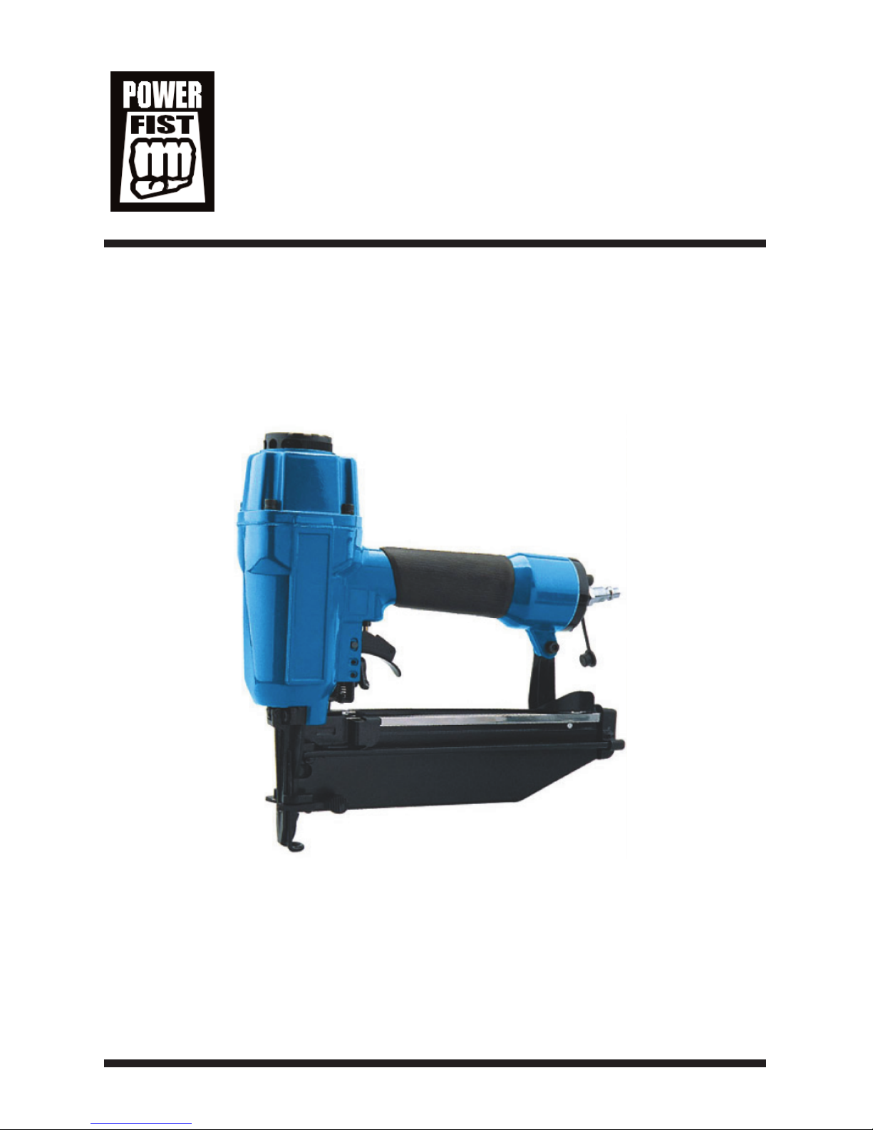
2-1/2" Air
Fini hing Nailer
8052409
Owner s Manual
Please read all safety and operating instructions before using
this product. Retain this manual for future reference.

Technical Data
• Capacity: 100 nails
• Nail length: 1-1/4" to 2-1/2"
• Fastener size: 16 Gauge
• perating pressure: 60 to 100 PSI
• Air inlet: 1/4" NPT
• Max pressure: 120 PSI
Important Safety Rule
1. KEEP CHILDREN AWAY. All children and visitors should be kept away
from the work area. Don’t let them handle the tool.
2. USE SAFETY GLASS AND EAR PR TECTI N: Air tool operators and
others in work area should always wear safety glasses to prevent injury
from fasteners and flying debris when loading and unloading nailer. Avoid
hearing loss by wearing ear protection.
3. NEVER USE XYGEN, C MBUSTIBLE or any other bottled gas as a
power source. It can cause explosion and serious personal injury.
4. D N T EXCEED MAX AIR PRESSURE of 120 PSI.
5. CARRY THE T L NLY BY THE HANDLE. To avoid unintentional
firing of fastener do not hold the trigger or pull on safety yoke mechanism
6. KEEP THE T L P INTED AWAY FR M Y URSELF and others at
all times and keep hands, any body parts away rear area to safe-guard
against possible injury.
7. DISC NNECT T L FR M AIR SUPPLY BEF RE L ADING
fasteners to prevent a fastener from being fired during connection.
8. D N T KEEP THE TRIGGER R SAFETY DEPRESSED during
loading fasteners or the unintentional firing of a fastener would cause
personal injury.
9. DISC NNECT T L FR M AIR SUPPLY H SE and close the
compressor before performing maintenance, alter the accessories or during
non-operation.
10. D N T DRIVE FASTENER N SCAFF LDINGS,LADDERS and on
such similarly construction, not working on airtight case, and vehicles.
11. D N T DRIVE FASTENERS CL SE T THE EDGE F THE

W RK PIECE. It may split allowing fastener to fly free or ricochet,
causing personal injury.
12. D N T DRIVE FASTENER N T P F NAILED FASTENER, as
the fastener can ricochet causing personal injury.
13. NEVER USE A T L that is leaking air, has missing or damaged parts
or requires repair. Make sure all the screws are securely tightened.
14. MAKE DAILY INSPECTI NS of trigger, safety mechanism and spring
to ensure the tool can operate well.
15. NLY USE PARTS AND ACCESS RIES recommended by the
manufacturer.
Operating In truction
Description
This nailer drives 16 gauge finishing nails from 1" to 2-1/2" long. Large cast
aluminum body provide more power to easily drive nails into hard wood.
Comfort grip rubber handle provides improved control and comfort even
during extended use. Features 360-degree exhaust port that can be adjusted
in any direction . Economical air consumption with low noise. Narrow nose
is ideal for door and window trims, decorative trim, and cabinet work, finish
paneling, interior finishing and furniture making.
Air Supply
1. Use clean, dry and regulated compressed air at 60-100 PSI.
2. Never exceed maximum and minimum pressure. Too low or too high
pressure would cause noise, faster wearing or misfiring.
3. When connecting air supply always keep hands and body from discharge
area of tool.
4. A filter-regulator-lubricator is recommended and should be located as
close to tool as possible.
5. Keep air filter clean. A dirty filter will reduce the air pressure to the tool
causing a reduction in power and efficiency.
6. For better performance, install a quick connector in your tool and quick
coupler on the hose.
7. Be sure all connections in air supply system are sealed to prevent air loss.

Loading Fasteners
WARNING: Always disconnect the tool from the compressed air before
loading. When loading the tool always point the tool away from
yourself and others. Make sure that you are not holding the tool
with trigger depressed while loading the tool.
1. Insert a strip of fasteners into magazine, keeping it point down.
2. Release the latch and pusher, slid the pusher against the nails.
3. Connect the tool to the air supply. Make sure the air pressure is in the
correct range denoted in the Technical Data.
4. Then test the driving depth in a sample piece of wood before using. If the
fasteners are being driven too far or not far enough, adjust the regulator to
provide less air pressure or more air pressure.
5. Never operate tool unless safety nose is contact with workpiece. Do not
operate tool without fasteners or damage to tool may result.
6. Never fire fasteners into air because fasteners may injury operator or
others and damage to tool may result.
7. The tool is equipped with a single firing safety system to protect the
operator.
Maintenance
Disconnect the tool from the air compressor before adjusting, clearing jams,
servicing, relocating and during non operation.
1. Regular lubrication, if your tool without using the in-liner automatic oilier,
place 2 or 6 drops of pneumatic tool oil into the air inlet before each work
day or after 2 hours of continuous use depending on the characteristic of
workpiece or type of fasteners.
2. Check and change all worn or damaged o-rings, seals, etc. Tight all the
screws and caps in case personal injury.
3. Inspect trigger and safety mechanism to assure safe system is complete
and functional: no loose and missing parts, no building or sticking parts.
4. Keep magazine and nose of tool clean and free of any dirt lint or abrasive
particles.

Trouble hooting
The following form lists the common operating system with problem and
solutions. Please read the form carefully and follow it.
WARNING: If any of the following symptoms appears during your
operating, stop using the tool immediately, or serious personal
injury could result. nly a qualified persons or an authorized
service center can perform repairs or replacement of tool.
Disconnect tool from air supply before attempting repair or adjustment.
When replacing -rings or Cylinder, lubricate with air tool oil before
assembly.
Problem
a. -ring in trigger valve
is damaged
b. Trigger valve head is
damaged
c. Trigger valve stem, seal
or -ring are damaged
a. Loose screws
b. Worn or damaged
-rings or bumper
a. Loose screws
b. Worn or damaged
-rings or seals
a. Worn bumper
b. Air pressure is too high
a. Inadequate air supply
b. Inadequate lubrication
c. Worn or damaged
-rings or seals
d. Exhaust port in cylinder
head is blocked
Solution
a. Check and replace
-ring
b. Check and replace
c. Check and replace
trigger valve stem, seal,
or -ring
a. Tighten screws
b. Check and replace
-rings or bumper
a. Tighten screws
b. Check and replace
-rings or seals
a. Replace bumper
b. Adjust the air pressure
a. Verify adequate air
supply
b. Place 2 to 6 drops of oil
into air inlet
c. Check and replace -
rings or seal.
d. Replace damaged
internal parts
Symptom
1. Air leak near top
of tool or in
trigger area.
2. Air leak near
bottom of tool
3. Air leak between
body and cylinder
cap
4. Blade driving
fastener too deep
5. Tool does not
operate well; can
not drive fastener
or operates
sluggishly

Problem
a. Worn bumper or
damaged spring
b. Dirt in front plate
c. Dirt or damage prevents
fasteners from moving
freely in magazine
d. Worn or dry -ring on
piston or lack of
lubrication
e. Cylinder cover seal
leaking
a. Incorrect or damaged
fasteners.
b. Damaged or worn driver
guide.
c. Magazine or nose screw
loose.
d. Magazine is dirty.
Solution
a. Repalce bumper or
pusher spring
b. Clean drive channel on
front plate
c. Magazine needs to be
cleaned
d. -ring needs to be
replaced and/or
lubricated.
e. Replace sealing washer.
a. Change and use correct
fastener.
b. Check and replace the
driver.
c. Tighten the magazine.
d. Clean the magazine
Symptom
6. Tool skips
fasteners
7. Tool jams

Part Li t

# Description
1 Bolt
2 Air deflector
3 Bumper washer
4 Bolt
5 Spring washer
6 Cylinder cover
7 -ring
8 Compressed spring
9 -ring
10 -ring
11 -ring
12 Switch valve
13 -ring
14 Collar
15 -ring
16 -ring
17 -ring
18 -ring
19 Main piston
20 Bumper
21 Washer
22 Cylinder cover
washer
23 Gun body
24 -ring
25 -ring
26 Trigger valve set
27 -ring
28 -ring
29 -ring
30 Trigger valve
guide
# Description
31 Switch spring
32 -ring
33 Switch valve stem
34 -ring
35 Switch valve seat
36 Pin
37 Trigger
38 Safety space
39 Trigger pin
40 -ring
41 Pin
42 Joint seat
43 Fixed block
44 Joint bolt
45 Steel ball
46 Spring
47 Safety seat
48 Pin
49 Snap retainer
50 Direction pin
51 Direction stand
52 Adjustment nut
53 Safety stand
54 Bolt
55 Fixed slice
56 Compressed spring
57 Block
58 Driver guide
59 Spacer
60 Snap retainer
61 Spacer pin
62 Cover plate
# Description
63 Bolt
64 Release latch
65 Bolt
66 Snap retainer
67 Pin
68 Bolt
69 Spring
70 Drive nail plate
71 Magazine
72 Nut
73 Bolt
74 Pin
75 Fixed seat
76 Spring
77 Pusher
78 Washer
79 Fixed lever
80 Strengthen slice
81 Bolt
82 Bolt
83 Washer
84 Support seat
85 Nut
86 Rubber handle
case
87 End cap washer
88 End cap
89 Air plug
90 Air plug case
Table of contents
Other Power Fist Nail Gun manuals

Power Fist
Power Fist SF5040 User manual

Power Fist
Power Fist 8558777 User manual

Power Fist
Power Fist 8558215 User manual

Power Fist
Power Fist 8314106 User manual

Power Fist
Power Fist 8990905 User manual

Power Fist
Power Fist 8990863 User manual

Power Fist
Power Fist 8134926 User manual

Power Fist
Power Fist 8549776 User manual

Power Fist
Power Fist 8865107 User manual

Power Fist
Power Fist 8005448 User manual