Power Inspired GATEWAY Series User manual

GATEWAY-2(B)S
700/1400W
On Demand AC Power
With Sleep function
1. INTRODUCTION
The GATEWAY Series are battery backed AC power supply designed for door access systems.
Unlike standard battery backup systems which revert to battery immediately following a power failure,
it is intended that the GATEWAY units remain off until awoken when needed with an external switch
contact. This prevents unnecessary battery discharge and extends power availability from hours to
weeks.
The Gateway 2S units can be used in standard UPS mode (where no remote contacts can be
incorporated) or in sleep mode. When in sleep mode the unit is activated using an external switch or
relay. Wireless relays or other controllers can also be incorporated using a 24Vdc supply provided by
the GATEWAY-2S. The Gateway-2BS models incorporate an internal mains first bypass facility. This
ensures mains power is always present on the output terminals whenever there is mains power
feeding the system. This is the case if the Gateway is active or not. The advantage of the bypass is
that output power will be available if the Gateway cannot be started due to a fault or flat internal
batteries.
When operating on battery, the unit outputs a high quality sine wave, as good as or better than you
would get from your normal utility supply which is essential to ensure reliable door operation. Note
that alternative systems may use non-sine wave inverters which are lower cost and simply not
designed to power motor type loads. This can cause mis-operation, system trips, excessive noise and
even damage to the motor or battery backup system itself.
GATEWAY BLOCK DIAGRAM

Power Inspired GATEWAY-2 Series Product Manual
MAN-GW-2(B)S Rev1.0
2. SYMBOLS USED IN THIS MANUAL
✍
A Useful Point To Note
⚠
A Warning which must be heeded or damage or injury could occur.
Danger of High Voltage
3. CAUTIONS & WARNINGS
⚠
Indoor Use Only
⚠
Do not operate the GATEWAY without the mains input plug being connected to an
earthed socket outlet.
⚠
Do not plug the GATEWAY input plug into the output socket.
⚠
Do not allow the GATEWAY to come into contact with any liquid.
Do not open the unit. Hazardous Voltages can exist even though the unit is switched
off.
4. Packaging
Upon receipt please inspect your GATEWAY for signs of damage in transit. The package contains:
●The GATEWAY unit
●An RJ11 connection lead.
●This manual.
●An IEC mains lead and loop through lead for IEC models
Optionally:
●ViewPower Software for remote monitoring
●A USB lead

Power Inspired GATEWAY-2 Series Product Manual
MAN-GW-2(B)S Rev1.0
5. IDENTIFICATION
❶
LCD Display
➏
Input Fuse
❷
On/Off Switch
➐
Remote Switch / 24Vdc RJ45/11
Connector
❸
RS232 (Serial) Communication Port
➑
Input AC Cord / IEC Input
❹
USB Communication Port
➒
UK Socket / IEC Outlets
❺
Cooling Fan (Active only when on battery
or in buck/boost mode)

Power Inspired GATEWAY-2 Series Product Manual
MAN-GW-2(B)S Rev1.0
LCD
❶
Indicates the Input Voltage to the GATEWAY
❷
Indicates the voltage on the GATEWAY Inverter. This is not necessarily the
voltage on the output sockets if the GATEWAY has the internal bypass option
fitted.
❸
Indicates the unit is operating in AC Mode. This happens if the unit is activated
when there is AC power present. If the indicator flashes, the unit will be
operating in Buck or Boost Mode.
❹
Indicates the power being drawn from the GATEWAY. Each segment
represents up to 25%.
❺
Indicates the GATEWAY is overloaded.
❻
Indicates the GATEWAY is operating from its batteries
➐
Indicates the charge left on the internal batteries. Each segment represents
approximately 25% of available charge.
➑
Indicates the battery is low and requires recharging.
➒
Indicates a fault has been detected with the GATEWAY.

Power Inspired GATEWAY-2 Series Product Manual
MAN-GW-2(B)S Rev1.0
6. INSTALLATION
If the unit is to be mounted in a ceiling void or at height, please ensure the unit is adequately
supported and cannot fall.
Ensure cables are not loose and cannot snag on moving parts
The GATEWAY must be installed indoors in an area free from excessive dust, moisture and
has adequate air flow. Do not place the GATEWAY next to sources of heat or in direct
sunlight.
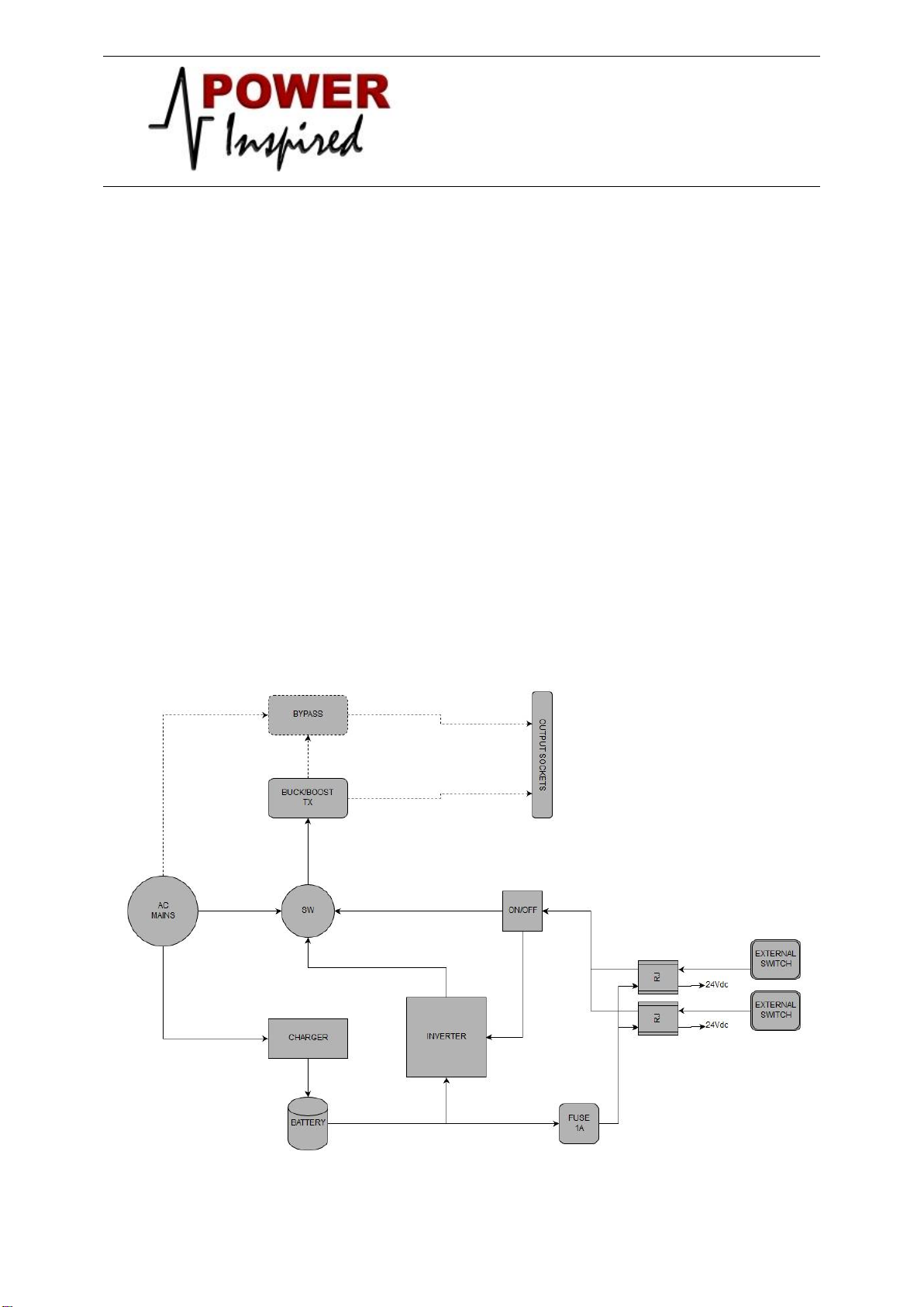
It is possible to have mains voltages appear with reference to earth on the output
connections from the GATEWAY rear panel connectors (See CONNECTIONS). These
voltages are impedance limited and not hazardous but may be perceived if exposed
conductors are touched. Always perform installation with the GATEWAY disconnected
from the mains, and ensure all cables and contacts are insulated, not exposed and
treated as though they were live conductors.
Depending upon the model the GATEWAY is fitted with either UK socket outlets or IEC
outlets. Connect the door motor supply to the most appropriate outlet.
Depending on the model the GATEWAY is fitted with either a fixed lead with a BS1363 plug,
or has an IEC mains input. An IEC lead is supplied, but may be replaced with a longer lead if
necessary. If this is the case ensure the conductor size is in excess of 1mm2. Connect the UK
plug on the GATEWAY or the mains lead as applicable into a suitable 13A outlet. This outlet
must be earthed.
The output RJ connectors contains a 24V supply to power accessories such as wireless
relays. This is fused at 1A. Note that the more power taken increases the drain on batteries
and minimises time between recharges.
⚠
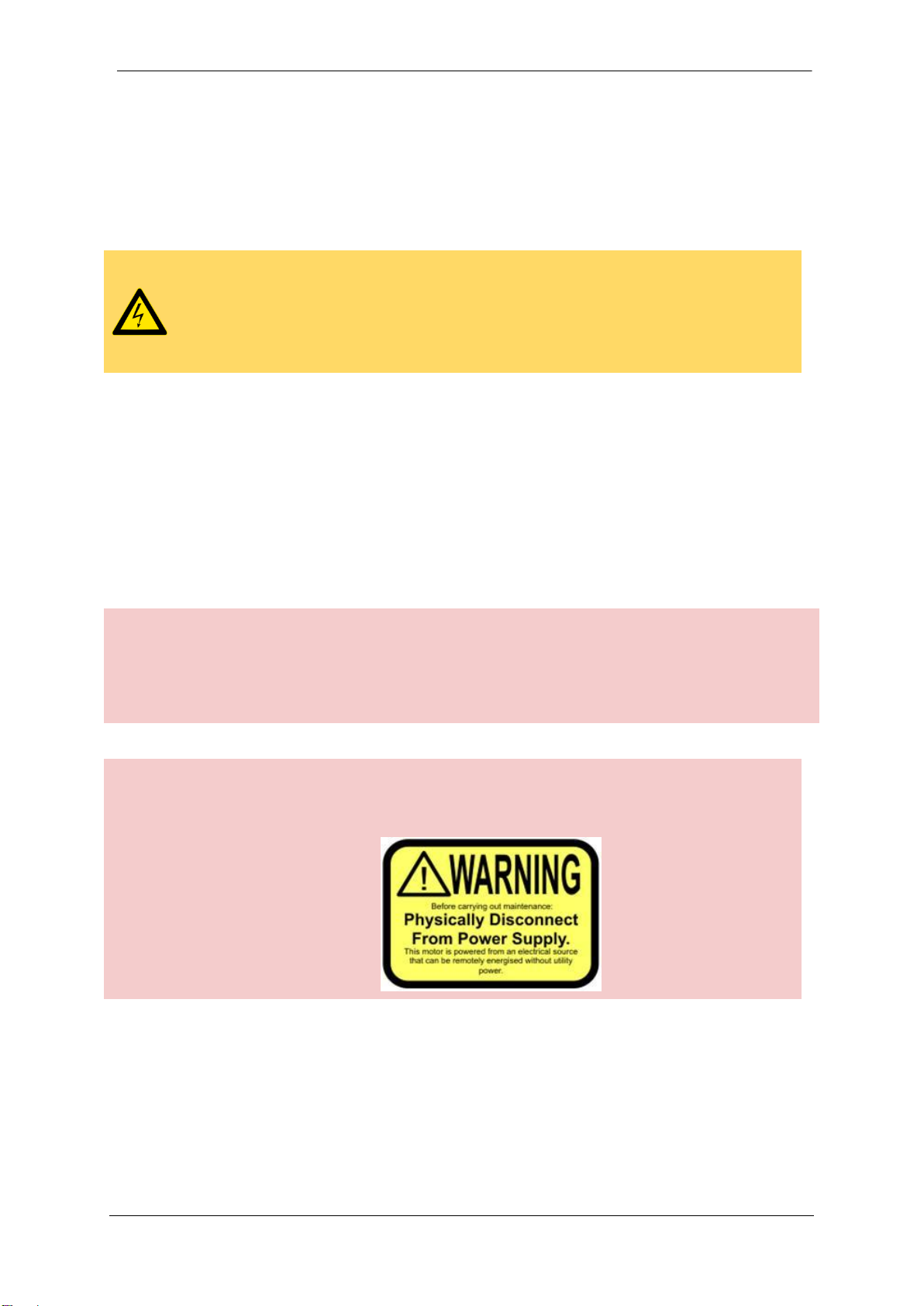
Since the GATEWAY can be started without mains power being present a warning label
should be placed on the motor to advise against maintenance without first physically
disconnecting the motor plug from the GATEWAY, such as:
⚠
Utilising the Gateway 24V supply will cause a drain on the batteries when no utility supply
is available. This can potentially lead to the batteries becoming discharged to a point of
non-recovery and require replacement. This is not covered under warranty. For longer
term use without utility power, it is recommended not to use the 24V supply and instead
use a remote key-switch if required.

Power Inspired GATEWAY-2 Series Product Manual
MAN-GW-2(B)S Rev1.0
7. CONNECTING TO AN EXTERNAL SWITCH OR CONTROLLER
On the rear of the GATEWAY are two RJ connectors which are connected as per the diagram
below.
Note the orientation of the connectors is inverse to each model (but the pin out is the same)
To remote start the unit the SW connections must be shorted together.
To switch the unit off the SW connection must be opened.
You can use either an RJ45 (network type) connector or an RJ11 (modem type) lead as supplied.
RJ45
pin
number
RJ11
pin
number
ID
Connection
Colour of
RJ11 Lead
as supplied
Other RJ11
Colour
Schemes*
1
X
X
Not Connected
2
1
X
Not Connected
N/C
N/C
3
2
SW
Switch Contact
YELLOW
BLACK
4
3
+24Vdc
+24Vdc Output
WHITE
RED
5
4
SW
Switch Contact
BROWN
GREEN
6
5
OV
0V
GREEN
YELLOW
7
6
X
Not Connected
N/C
N/C
8
X
X
Not Connected
✍
Either of the RJ connectors can be used. If required two external switches can be
connected. This is useful, for example, if you had a wireless relay and a keyswitch. Note
however that the connections are not isolated from one another. The unit will be
powered ON if either of the SW connections are closed.
⚠
* Confirm the pin out of the cable you are using before connecting to external devices
⚠
Do not short +24Vdc to 0V. The internal fuse will blow.
⚠
Do not connect any of the output connections to earth.

Power Inspired GATEWAY-2 Series Product Manual
MAN-GW-2(B)S Rev1.0
6. OPERATION –Remote / Sleep Mode
Switch on utility power supplying the GATEWAY. It is suggested to ensure the GATEWAY
has at least 6 hours of uninterrupted connection to the utility to ensure the batteries are
adequately charged.
✍
You can still operate the door whilst the GATEWAY is charging.
Make sure the front panel switch is in the OFF position and the GATEWAY is showing no
output voltage.
Whilst connected to the utility the LCD display will be ON and the batteries will be charged or
charging. The display will show the input mains voltage and the output voltage will be
displayed as zero.
⚠
B-Series Only: Although displayed as zero there will be power at the output sockets as
the internal bypass will be active.
✍
B-Series Only: Whilst utility power is present you can use your door as normal, the
GATEWAY does not need to be turned on.
Should the utility power fail, the GATEWAY will switch off and the LCD will be blank.
To obtain power to the door motor in the event of a power outage, the GATEWAY needs to be
switched on. Shorting the SW connections on any of the RJ connectors will start the
GATEWAY.
✍
It will take several seconds before the GATEWAY delivers power if requesting start up
when no mains power is available. When mains power is present the GATEWAY will
switch on within a few seconds.
✍
Non-B-Series: The GATEWAY will provide AC power through a voltage regulator system.
This may mean the output voltage is higher or lower than the input voltage.

Power Inspired GATEWAY-2 Series Product Manual
MAN-GW-2(B)S Rev1.0
7. OPERATION –UPS Mode
Switch on utility power.
Switch the front panel ON
✍
In the event of a power outage, in this mode the GATEWAY will revert to battery operation
immediately. The unit will continue to operate on battery power until either mains power
returns, or the batteries become too low.
⚠
If the batteries are allowed to discharge under low or no-load conditions they may
become unusable due to deep battery discharge. This may cause issues in restarting
the GATEWAY and the unit may require battery replacement.
✍
The +24V supply is still available to use through the RJ connector but it is not advised to
use a remote switch contact. This will have no effect, but if the switch contacts are closed
this will override the front panel switch e.g. you will not be able to switch the unit off.
✍
In UPS mode power is present at the output sockets at all times.
✍
Note the GATEWAY will provide AC power through a voltage regulator system. This may
mean the output voltage is higher or lower than the input voltage.

Power Inspired GATEWAY-2 Series Product Manual
MAN-GW-2(B)S Rev1.0
9. SPECIFICATIONS
Model
GW700-2S
GW1400-2S
Capacity (Max Watts)
700W
1400W
Input Voltage
230VAC 50Hz Nominal
Input Voltage Range
162-290VAC
Output Voltage Regulation
230VAC ±10% (Battery Mode). As input
Output Waveform
Sine Wave (On battery). As Input in normal Mode
Internal Battery
2X12V 7Ah
2X12V 10Ah
Charge Time
6 hours from depleted to 90% capacity
Input Connection
UK BS1363 Plug On 1.5M Cord
-or-
IEC C14 input
Output Connections
4X BS1363 UK Socket Outlets
-or-
4xIEC C13 Outlets
6xIEC C13 Outlets
Operational Connector
2x RJ connectors
Dimensions W x D x H
146 x 350 x 160 mm
146 x 397 x 205 mm
Weight
9kg
14kg
Operating Environment
Humidity 0-90% RH Non Condensing, Temperature 0-40°C
Audible Noise
< 45dB (Alarm)
<55dB (Alarm + Fan). Note fan
only operates in Battery /
Voltage Regulation Mode

Power Inspired GATEWAY-2 Series Product Manual
MAN-GW-2(B)S Rev1.0
10. TROUBLESHOOTING
PROBLEM
POSSIBLE CAUSE
SOLUTION
LCD Display Blank
No Mains Power
Connect Power. Check Fuse.
Poor AC input connection
Confirm Connection
Unit starts up on battery but
switches off when door is
activated
Insufficient Charge On
Batteries
Recharge for 6 hours. If
problem persists replacement
batteries are required.
Alarm continually sounds and
warning or fault icon is on the
LCD
Fan locked
Check Fan (GATEWAY1400
only)
Unit is overloaded
Confirm motor rating including
start up rating is under
maximum capacity of the
GATEWAY
Output Voltage display is
different to input voltage
display when GATEWAY is
activated. AC Icon flashes
Unit is regulating voltage and is
in buck or boost mode.
Normal Operation
Alarm sounds intermittently
when GATEWAY is activated
Unit is operating from battery
power.
Confirm AC input power is
present and within
specification.
Batteries are depleted after a
few days without mains power
Excessive Operation without
mains
Try to reduce frequency of door
operation
Power Drain on 24V supply
Check standby current on
accessories connected to 24V
supply or remove during
extended outages.
No DC output
Incorrect Wiring
Confirm wiring as per pin out
diagram
Blown Fuse
Replace the internal fuse.
Contact Power Inspired for
advice.

Power Inspired GATEWAY-2 Series Product Manual
MAN-GW-2(B)S Rev1.0
11. WARRANTY
1. The Gateway is warranted from defects in material and workmanship under normal use
during the warranty period.
2. During the warranty period Power Inspired will repair or replace at no charge, the product or
parts of it that proves defective because of improper material or workmanship under normal
use or maintenance.
3. The warranty period is 2 years from date of despatch for the unit and 1 year for the internal
batteries. Note that dead batteries caused by failure to adhere to the requirements contained
in this manual is not covered under warranty.
4. If you suspect your GATEWAY has a problem that is covered under warranty then you must
first contact us to obtain an RMA number. Once issued you must securely package the unit
and return it to us at the address given under “Contact Information”. Power Inspired will
inspect, test and repair the unit, and send the unit back to you.
5. This warranty does not cover any problems caused by conditions, malfunctions or damage
not resulting from defects in material or workmanship, nor for any losses incurred due to the
failure of the product. Please refer to our Terms & Conditions of Sale located at
https://www.powerinspired.com/commercial/trade-terms-conditions-sale/
12. CONTACT INFORMATION
Address:
POWER INSPIRED LTD
Unit 122
Churchill Road
Bicester
Oxfordshire
OX26 4XD
United Kingdom
Tel : +44 (0) 1869 814055
W: www.powerinspired.com

Power Inspired GATEWAY-2 Series Product Manual
MAN-GW-2(B)S Rev1.0
DECLARATION OF CONFORMITY
In accordance with the Low Voltage Directive 2006/95/EC and the EMC Directive 2004/108/EC.
The GATEWAY series of Door Access UPS is certified to comply with the following directives:
Low Voltage Directive 2006/95/EC
In accordance with:
EN60950-1:
EN62040-1
EMC Directive 2004/108/EC:
In accordance with:
EN62040-2
EN61000-4-2/3/4/5
EN6100-2-2
T Bell BEng MIET
Director
11 April 2017
POWER INSPIRED LTD., Unit 122, Churchill Road, Bicester, Oxfordshire, OX26 4XD. UK

Power Inspired GATEWAY-2 Series Product Manual
MAN-GW-2(B)S Rev1.0
NOTES

Power Inspired GATEWAY-2 Series Product Manual
MAN-GW-2(B)S Rev1.0
UNIT122
CHURCHILL ROAD
BICESTER
OXFORDSHIRE
OX26 4XD
TEL: 01869 814055
E: info@powerinspired.com
W: www.powerinspired.com
This manual suits for next models
2
Table of contents
Other Power Inspired Power Supply manuals
Popular Power Supply manuals by other brands

M-system
M-system R3Y-SS16N instruction manual

MW
MW HDR-15 Series installation manual

Bosch
Bosch AL 1830 CV Original instructions

Rockwell Automation
Rockwell Automation Allen-Bradley 1606-XLE240EDRZ SER B installation instructions

BFI Automation
BFI Automation 3002 Original operating instructions

PeakTech
PeakTech 6225 A Operation manual