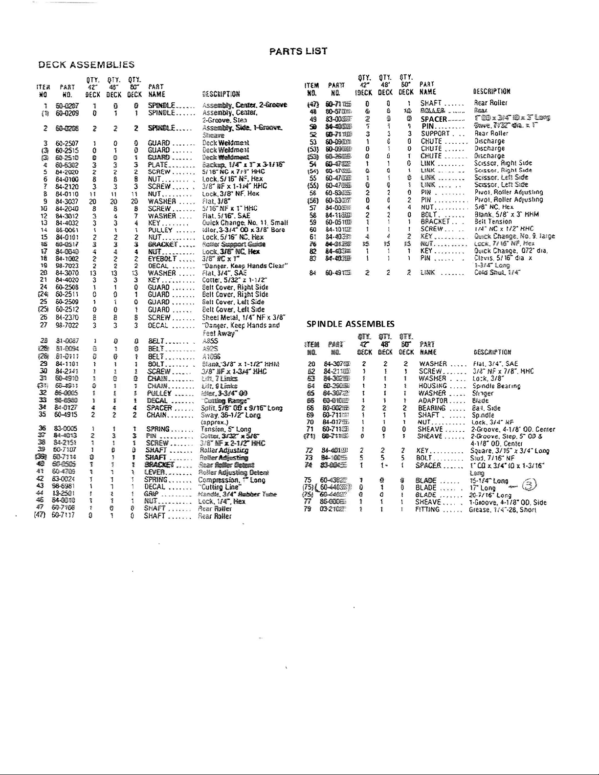
Step1. Install Model 60‐012 Hitch following separate installation
instructionsprovidedwiththehitchitself.
Step2. Screws(item10)andNuts(Item6)onthedischargeChute
(Item 5) have been tightened before shipment to prevent possible
damage. The Screws and Nuts should be loosened just enough to
allow the Chute to swing upward feely as needed for storage or
transportingthroughnarrowpassageways.TheChuteshouldalways
bedownwhilemowing.
Step3. Mount cutting height adjustment lever (Item 41) on right
end of roller adjusting Shaft (Item 39) by inserting Screw (Item 45)
through Washer (Item 11), clevis end of Lever, and Shaft. Secure
withNut(Item46).ThenmoveLeverallthewayforwardintolowest
cuttingheightposition.
Step4. Withthenoseofthedeckpointingforward,slidethedeck
under the tractor from the right side as far as possible. Turnthe
frontwheelsallthewaytotheleftamdliftthedraglinkWeldment
(Item19)overtherightfrontwheel.
Step5. InsertasmallquickchangePin(Item29)throughthehole
in the lift arm of the tractor and through the end link of the Chain
(Item31)locatedonthetopofthedeck.
Step6. MovetheimplementLiftLeveronthetractortotherearin
ordertoraisethefrontofthedeck.
Step7. Align holes with welded spacers at front of drag link
Weldment(Item19)withthemiddleofthethreeholesatthelower
rearofthehitchandsecurewithablankBolt(Item18–HitchParts
List)andquickchangeKey(Item20–HitchPartsList).Moveliftlever
forwardtolowerdeck.
Note:Themiddleholeisusedforinitialinstallation.Asthebelt
stretcheswithuseitmaybedesirabletousetherearmosthole
in the hitch. If so, follow belt adjustment procedure provided
below.
Step8. Withthedeck loweredintooperating position, makesure
thatall6Rollers(Item48)aremakingcontactwiththelevelground.
Ontheleftsideofthedeck,measurethedistancefromthefronttip
oftheleftcuttingblade(Item75) to a flat, level ground surface.
Makethesamemeasurementfromthereartipofthesameblade.
Thedistanceshouldbethesame,frontandrear,onallthreeblades.
Ifthefronttipofthebladeislowerthantherear,loosentheouter
Nut(Item57)attherearofthescissorslinkRods(Items54and55)
andturntheinnerNut(Item57)againsttherolleradjustingpivotPin
(Item56)untiltheblademeasurementisthesameatfrontandrear
tips.Reversetheprocedureifthereartipofthebladeislowerthan
thefront.
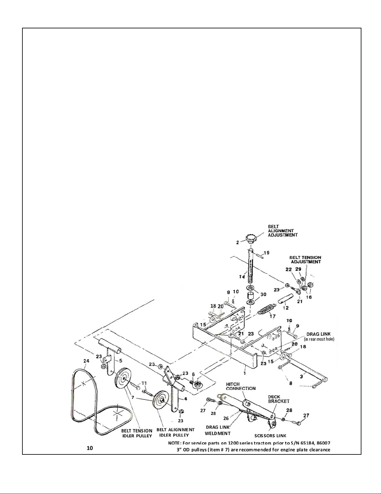
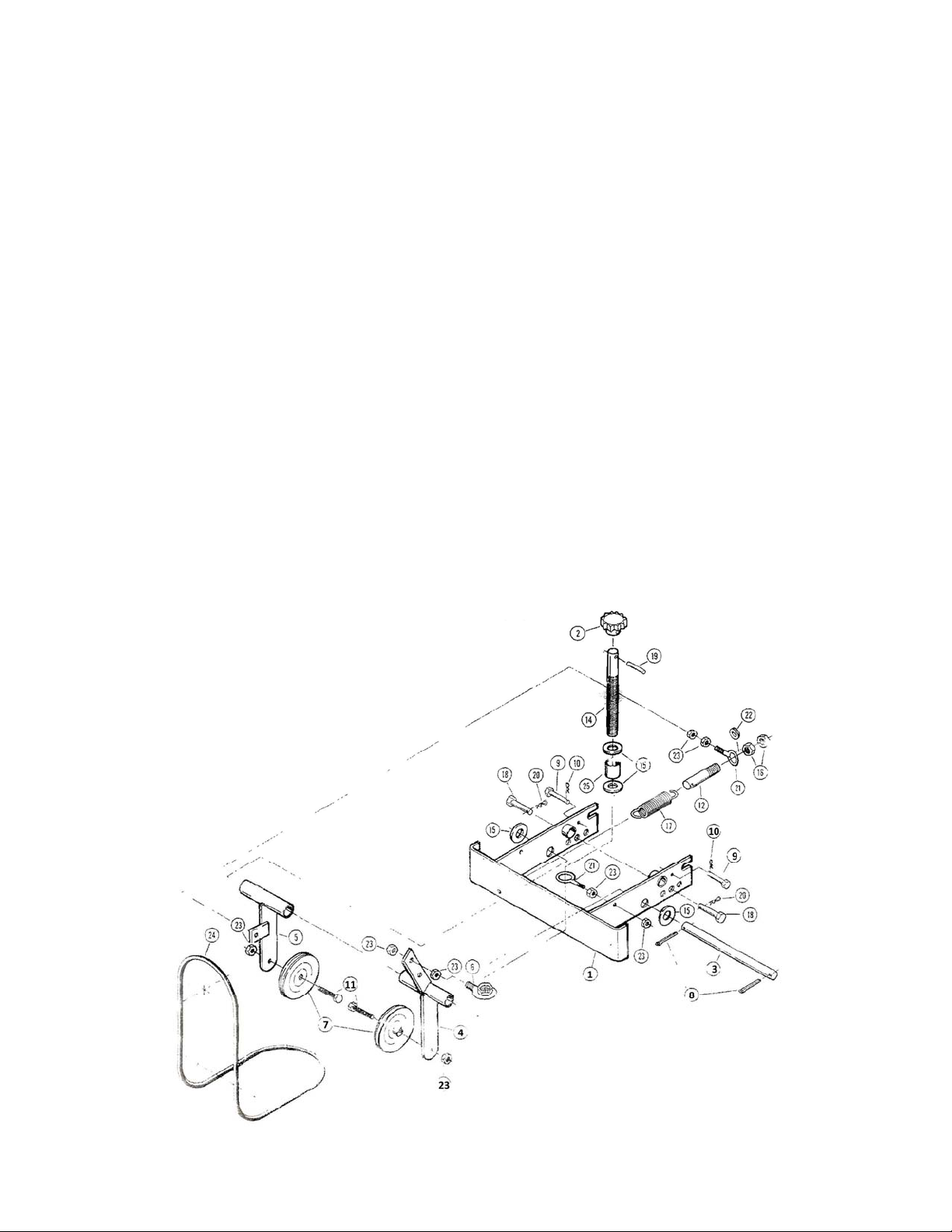
Step9. Facingthefrontofthetractorwiththeengineoff,loopthe
drive belt (Item 24 – Hitch Parts List) over the front groove of the
electromagneticclutchonthefrontoftheengine.Thenturnthebig
blackKnob(Item2–HitchPartsList)counterclockwiseenoughtoget
the drive Belt under the two Pulleys (Item 7 ‐ Hitch Parts List) and
aroundthetopgrooveofthecenterSpindle(Item1)ontopofdeck.
Step10. SetthecuttingheightadjustmentLevertomowershighest
cuttinglevel.TurnthebigblackKnobuntilthebeltonthesameside
astheKnobjustclears(1/8”)thenoseofthedeck.Alsochecktobe
sure the tension Spring (Item 17 – Hitch Parts List) controlling the
pulley on the other (left) side is tight with a little stretch on it.
TightenNut(Item16‐HitchPartsList)ontensionRod(Item12 –
HitchPartsList)ifnecessary.
Step11. SetthecuttingheightadjustingLevertothemowerslowest
cuttingheightandtightentheinnerNutonthebelttensionRoduntil
thetensionSpringisstretched3/8”toanapproximate length of 3‐
9/16”acrossthecoils.TightentheouterNutagainsttheinnerNutto
lockSpringatthatlength.
Step12. Whenoperatingmowerforthefirsttime.stopafterabout
15minutesandagainrecheckdecklevelandbeltalignment.
Lubrication
Toallowforwear,partsarelikelytofitsnuglywhentheyarenew.
Untiltheyhave“worn‐in”,theycanbemadetofunction
successfully with a few drops of lubricating oil at working joints.
Thereafter, especially after washing out under the deck, apply
lubricating oil to the linkage, rollers, and other pivot points
frequently. Spindles should be lubricated every 50 hours of
operation with a good multi‐purpose bearing grease. The grease
Fittings (Item 79) are located on each spindle Housing (Item 64)
underneath the deck. Wipe the Fitting clean before greasing to
preventdirtfrombeingforcedintotheBearings(Item68).Be
carefulnot tooverfillthe spindle since toomuchgrease pressure
maydamageseals.
CuttingHeight
ThelengthofthegrassaftercuttingisregulatedbytherearRollers
(Item 48). To adjust the position of the rear Rollers, raise the
mowerwiththeimplementliftHandleonthetractor(seeassembly
step6).Thenmovethecuttingheightadjustmentleverforwardto
lowertheheightofcutorrearwardtoraiseit.Lowerthemowerby
moving the implement lift Handle all the way forward. This will
allow all six rollers to rest on the ground. When transportingthe
deckfromthecuttingareatothestoragearea,setthecutting
heightadjustmentlevertothepositionmarkedwitha“T”.Thiswill
providemaximumgroundclearanceforallmowerpartsandprotect
thebladesanddeckfromdamage.
BladeCare
Always keep blades (Item 75) sharp and blade mounting Screw
(Item62)tight.Amaximumof22ft/lbs.oftorqueisrecommended.
NeverattempttotightenthebottomblademountingScrewortop
spindleNut(Item70)withouthavingthecuttingbladeinpositionto
prevent possible damage to the aluminium hub. To sharpen, file
alongtheoriginalbevel, usingcare nottofilematerialoff theend
as the length of the blade is important to maintain cutting circle
overlapandbladebalanceforacleancut.Whensharpening,check
balance of the blade with a rod or the shank of a screwdriver
through the center hole to see if both ends rest evenly. File the
heavysideuntileven.
BeltReplacement
After prolonged use, belts may show signs of wear by fraying or
cracking. If this occurs, the belt should be replaced as soon as
observedtopreventbreakingduringmowing.
ToreplacethemowerCrossBelt(Item28),removebothbelt
Guards(Items24and25)andtheoldbelt.ThreadnewBeltaround
lower groove of the center spindle (Item 71), both left and right
sidespindles(Items2),andthetwoidlerPulleys(Items14and32)
as shown in exploded view drawing insert. Replace both belt
Guards.
ToreplacetheDriveBelt(Item24–HitchPartsList)turntheblack
serratedknobontheHitchcounterclockwisetoloosenthetension
onthebelt.Removetheoldbeltfromtheuppergrooveofthe
centerspindleonthedeckandthefrontmostgrooveofthepulley
ontheelectromagneticclutchonthefrontoftheengineandfeedit
throughthebottomoftheHitch.Refertosteps9–12for
reinstallationofthenewdriveBelt.