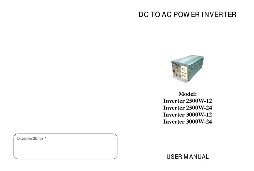
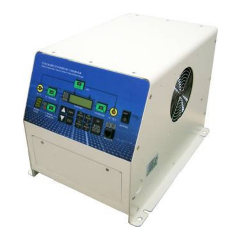
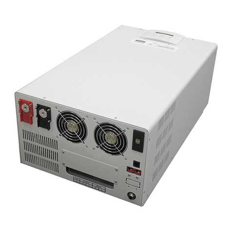
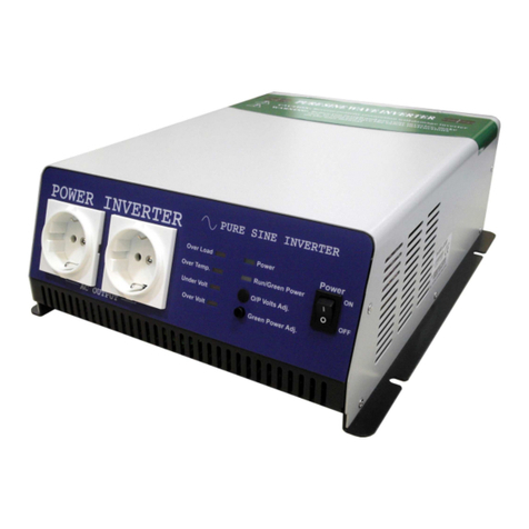
Power Master PM-2500 User manual

0

1
C O N T E N T S:
1.GENERAL SAFETY PRECAUTIONS………………………………………………3-4
2.ELECTRICAL SAFETY PRECAUTIONS……………………………………………4-5
3.SAFETY INFORMATION………………………………………………6-7
4.CONTROL FUNCTION……………………………………………7-9
5.PRE-OPERATION CHECK……………………………………………10-11
6.OPERATION…………………………………………………………11-13
7.PERIODIC MAINTENANCE…………………………………………14-17
8.TROUBLE SHOOTING………………………………………………17
9.STORAGE…………………………………………………………17-18
10.SPECIFICATIONS…………………………………………………19-20
11.WIRING DIAGRAM…………………………………………………21-22

2
IMPORTANT:
Thank you for purchasing a Power Master Gasoline Generating Set (hereinafter referred to as the “generator”).
This manual will assist you in operating and maintaining your generator. This manual is the latest version. With
the continuous improvement and upgrading of this product, the manufacturer reserves the right to modify this
manual without notice. The manufacturer shall assume no liability for incorrect information contained in this
manual.
This manual is an integral part of the generator. When the generator is transferred to others, this manual should
be handed over to the new owner.
Some important information in this manual will be indicated in the following way ,please see below). The users
should pay special attention to these instructions.
The range of POWER MASTER GENERATORS is safe and reliable, but incorrect use of these products
may cause personal injury and or damage to your machine. Please read this manual thoroughly before
operation as this product is required to operate strictly in accordance with this manual.
IMPORTANT NOTICES:
PLEASE PAY SPECIAL ATTENTION TO STATEMENTS PRECEDED BY THE
FOLLOWING WORDS:
Danger
•DANGER
This indicates a hazardous situation, which, if not avoided, will result in death or serious
injury.
Warning
•WARNING:
This indicates a hazardous situation, which, if not avoided, could result in death or serious
injury.
Caution

3
•CAUTION:
This indicates a hazardous situation, which, if not avoided, could result in injury.
1. GENERAL SAFETY PRECAUTIONS:
Danger Warning Caution
1.1. A “LAYMAN” and or “CHILDREN” may not recognize the possible dangers of operating a
generator. We recommend that only competent persons should operate the generator.
1.2. Fuel is combustible and easily ignited. Do not refuel during operation.
1.3. Do not refuel whilst smoking or near naked flames. Do not overfill or spill fuel. If this happens
clean the fuel on and around the generator properly before operating.
1.4. Only use the specified fuel when operating the generator
1.5. Some parts of the internal-combustion engine are hot and might cause burns. Pay attention to
the warning signs on the generating set.
1.6. Engine exhaust gases are toxic. Do not operate the generator in an unventilated room. When
installed in a ventilated room, additional requirements for fire and explosion protection must be
observed.
1.7. Regularly check that the bolts and nuts are properly tightened as they may become lose due to
vibration of the generator whilst in use.
1.8. Before using the generator ensure that you have checked the periodic maintenance schedule in
the operator’s manual.
1.9. Pay attention to the wiring or extension cords from the generator to the connect device. If the
wire is under the generator or in contact with a vibrating part, it may break and possibly cause a
fire, generator burnout, or electric shock hazard. Replace damaged or worn cords immediately.
1.10. Do not operate in rain, wet or damp conditions, or with wet hands. The operator may suffer
severe electric shock if the generator is wet.
1.11. If wet, wipe and dry it well before starting. Do not pour water directly over the generator, nor was
hit with water.
1.12. Be extremely careful that all necessary electrical grounding procedures are followed during
each and every use. Failure to do so can be fatal.
1.13. Do not connect the generator to a commercial power line. Connecting to a commercial power
line may short circuit the generator. We strongly recommend the use of a Transfer Switch for
connecting to a domestic circuit.
1.14. Do not smoke when handling the battery. The battery emits flammable hydrogen gas, which
can explode if exposed to cigarettes and or naked flames. Keep the area well-ventilated and
keep naked flames/ sparks away when handling the battery.
1.15. Keep children and all bystanders at a safe distance from the genertor whislt in use

4
1.16. It is absolutely essential that you know and understand the safe and proper use of the power
tool or appliance that you intend to connect to the generator. All operators must read,
understand and follow the tool/ appliance operators maunal. The tool and appliance
applications and limitations must be understood. Keep all instruction manuals in a safe place for
future reference.
1.17. Always switch off the circuit breaker on the generator when not in use.
2. ELECTRICAL SAFETY INFORMATION:
2.1. Electrical equipment including cable, cords and plug connection must not be defective. Please
check before using.
2.2. Do not plug the generator directly into a wall socket-outlet.
2.3. The generator should not be connected to other sources such as the power company supply
mains. In special cases where stand-by connection to existing electrical systems or integration
therewith is intended, note that it is a legal requirement that such connections or integration may
only be performed by a competent person.
2.4. Protection against electrical shock depends on circuit-breakers that are specially matched to the
generator. If a circuit breaker requires replacement, it shall be replaced by a circuit breaker that
has identical ratings and performance characteristics.
2.5. Due to high mechanical stresses only tough rubber-sheathed flexible cable should be used.
2.6. If the generator is of CLASS II construction then earthing of the generator is not required.
2.7. Cord Extension Sets:
2.7.1. A 1mm2 flexible cable can draw a maximum of 10A provided that the cable is not longer
than 25m.
2.7.2. A 1.5mm2 flexible cable can draw a maximum of 10a provided that the cable is not
longer than 35m
2.7.3. A 1.5mm2 flexible cable can draw a maximum of 16a provided that the cable is not
longer than 20m
2.7.4. A 2.5mm2 flexible cable can draw a maximum of 10a provided the cable is not longer
than 65m
2.7.5. A 2.5mm2 flexible cable can draw a maximum of 16a provided that the cable is not
longer than 45m
2.7.6. A 4mm2 flexible cable can draw a maximum of 10a provided that the cable is not longer
than 100m
2.7.7. A 4mm2 flexible cable can draw a maximum of 16a provided that the cable is not longer
than 65m
2.8. DROP IN ELECTRIC EXTENSION CORDS:

5
When a long electric extension cord is used to connect an appliance or tool to the generator, a certain amount
of voltage drop or loss occurs in the extension cord which reduces the effective voltage available for the
appliance or tool.
The chart below has been prepared to illustrate the approximate voltage loss when an extension cord of 300
feet (approx.100 meters) is used to connect an appliance or tool to the generator.

6
hot
cool air
! WARNING ──────────────────────────────────
PLEASE READ AND UNDERSTAND THIS MANUAL COMPLETELY BEFORE OPERATING THE
MACHINE.
3.SAFETY INFORMATION
1)EXHAUST FUMES ARE POISONOUS
zNever operate the generator in a closed area or it may lead to unconsciousness and possible death.
Always operate the generator in a well ventilated area.
2)FUEL IS HIGHLY FLAMMABLE AND POISONOUS
zAlways turn off the generator when refueling
zNever refuel while smoking or in the vicinity of an open flame.
zTake care not to spill any fuel on the engine or muffler when refueling.
zIf you swallow any fuel, inhale fuel vapor, or allow any to get in your eyes, see your doctor immediately. If
any fuel spills on your skin or clothing, immediately wash with soap and water and change your clothes.
zWhen operating or transporting the generator, be sure it is kept upright. If it tilts, fuel may leak from the
carburetor or fuel tank.
3)ENGINE AND MUFFLER MAY BE HOT
zPlace the generator in a place where children are not likely to touch the machine.
zAvoid placing any flammable materials near the exhaust outlet during operation.
zKeep the generator at least 1 m ( 3 ft ) from buildings or other equipment, or the generator may overheat.
zAvoid operating the generator with a dust cover.
zBe sure to carry the generator only by its carrying handle.
zPlace the generator on a flat surface to ensure that the machine
can eliminate heat freely.
4)ELECTRIC SHOCK PREVENTION
zNever operate the generator in a wet enviroment. Keep out of
the rain.
zNever touch the generator with wet hands as this may result in an electrical shock.
zBe sure to ground (earth) the generator.
NOTE: ───────────────
Use the correct cable
Diameter: 0.12mm (0.005 in)/ampere
EX: 10 Ampere --1.2mm (0.055 in)
──────────────────

7
123 45
67
813 1516 17
19 20
910 14 18
11 12
5)CONNECTION NOTES
zDo not connect the generator directly to the Utility Power Source.
zDo not connect the generator in parallel with any other generator.
4.CONTROL FUNCTION
DESCRIPTION
(
1
)
Econom
y
control switch
(
2
)
En
g
ine switch
(
3
)
Fuel tank
(4) Spark plug (5) Muffler (6) Carrying handle
(7) Choke lever (8) AC pilot light (9) Overload indicator light
(
10
)
Oil warnin
g
li
g
h
t
(
11
)
DC protecto
r
(
12
)
DC receptacl
e
(13) AC receptacle (14) Ground (earth) terminal (15) Fuel filter
(
16
)
Fuel tank cap
(
17
)
Recoil starte
r
(
18
)
Fuel cock
(
19
)
Oil filler ca
p
(
20
)
Air filter cove
r

8
123 45
67
811 131415 16
18 19
910 12 17
(
1
)
Econom
y
control switch
(
2
)
En
g
ine switch
(
3
)
Fuel tank
(4) Spark plug (5) Muffler (6) Carrying handle
(7) Choke lever (8) AC pilot light (9) Overload indicator light
(
10
)
Oil warnin
g
li
g
h
t
(
11
)
AC receptacle
(
12
)
DC receptacle
(13) Ground (earth) terminal (14) Fuel filter (15) Fuel tank cap
(16) Recoil starter (17) Fuel cock (18) Oil filler cap
(
19
)
Air filter cover

9
O
FF
O
N
1)OIL WARNING SYSTEM
When the oil level falls below the lower level the engine will stop
automatically. Unless you refill with oil the engine will not start again.
2)ENGINE SWITCH
The engine switch controls the ignition system.
①“ON”(run)
When the ignition circuit is switched on the engine will start.
②“OFF”(stop)
When the ignition circuit is switched off the engine will not run.
3)ECONOMY CONTROL SWITCH
When the economy control switch is switched “ON”, the economy
control unit controls the engine speed according to the load. This may
result in better fuel efficiency as well as lower noise.
4)DC CIRCUIT PROTECTOR
The DC circuit protector turns off automatically when the load exceeds
the generator rated output.
CAUTION: ─────────────────────
zReduce the load to within specified generator rated output if the DC
circuit protector turns off.
───────────────────────────
5)FUEL TANK CAP AIR VENT KNOB
The fuel tank cap is supplied with an air vent knob to stop fuel flow.
The air vent knob must be turned once clockwise from the closed
position. This will allow fuel to flow to the carburetor and the engine to
run.
When the engine is not in use, tighten the air vent knob
counterclockwise until it is finger-tight to stop fuel flow.
6)FUEL COCK
The fuel cock is used to supply fuel from the tank to the carburetor.
OPEN /CLOSED
2
1
2
1

10
OFF
ON
5. PRE-OPERATION CHECK
NOTE: ────────────────────────
zAdd at least 2 liters of fuel when using the generator for the first time.
zPre-operation checks should be made each time the generator is
used.
───────────────────────────
1)CHECK ENGINE FUEL
zMake sure there is sufficient fuel in the tank.
zIf fuel is low refuel with clean unleaded gasoline.
zBe sure to use the fuel filter screen on the fuel filter neck when fueling
the generator.
zUnleaded fuel is recommended for this generator.
zFuel tank capacity: (see page 19,20)
WARNING: ──────────────────────
zDo not refuel the tank while generator is running or hot.
zClose the fuel cock before refueling.
zKeep the fuel free from dust, dirt, water or other foreign objects.
zDo not over fill when fueling the generator.
zWipe off spilt fuel thoroughly before starting engine.
zKeep away from fire.
──────────────────────────
2)CHECK ENGINE OIL
Make sure the engine oil is at the upper level of the oil filler hole. Add oil
as necessary.
zRemove oil filler cap and check the engine oil level.
zIf oil level is below the lower level line, refill to the upper level line. Do
not screw in the oil filler cap when checking oil level.
zChange oil if contaminated.
zOil capacity: (see page 19,20)
zRecommended engine oil:
API Service “SJ”
32°FF
80°
25° CC
0°
or 10W-30
SAE #30
or 10W-40
SAE #20
or 10W-30
or 10W-40or 10W-40
or 10W-30
SAE 10W

11
O
FF
O
N
ON
ECON.
SW
OFF
ON
ENGINE
SWITCH
ON
OFF
3)GROUND (Earth)
Make sure to ground (earth) the generator.
6. OPERATION
NOTE: ────────────────────────
zThe generator has been shipped without engine oil. Fill with oil or
it will not start.
zDo not tilt the generator when adding engine oil. This could result
in overfilling and damage to the engine
───────────────────────────
1)STARTING THE ENGINE
NOTE: ──────────────────────
zDo not connect any load to the generator until the generator has
been started and is running smoothly
zTurn the economy control switch to the “OFF” position.
─────────────────────────
1. Open the fuel tank air vent to the “OPEN” position.
2. Turn the fuel cock lever to the “ON” position.
3. Turn the engine switch to the “ON” position
4. Turn the choke lever to the “││”position. Not necessary if the
engine is warm.
5. Pull the starter handle slowly until resistance is felt. This is the
“Compression” point. Return the handle to its original position and
pull swiftly. After starting, allow the starter handle to return to its
original position while still holding the handle. Hold the carry handle
of the generator firmly to avoid the generator from falling over when
pulling the recoil starter.
6. Allow the generator to warm up before returning the choke lever to
its original position.
7. Allow the generator to run without a load for a few minutes.
2)USING ELECTRIC POWER
1. AC APPLICATION
a. Check the AC pilot lamp to see the voltage output.
OPEN

12
ECON.
SW
OFF
ON
b. Turn the economy control switch to the “ON” position.
c. Turn off the switch(es) of the electrical appliance(s) before connecting
to the generator.
d. Insert the pulg(s) of the electrical appliance(s) into the receptacle.
CAUTION: ─────────────────────
zEnsure that the appliances are “OFF” prior to connecting to the
generator.
zEnsure that the total load is within generator rated output.
zEnsure that the socket load current is within socket rated current.
zThe economy control switch must be turned to “OFF” when using
electric devices that require a large starting current such as fridges,
freezers etc.
──────────────────────────
2.OVERLOAD INDICATOR LIGHT
The overload indicator light comes on when an overload of a connected electrical
device is detected, the inverter unit overheats or the AC output voltage rises. The
electronic breaker will then activate stopping power to the generator in order to
protect the generator and any connected electrical devices. The output pilot light
(green) will flicker and the overload indicator light (red) will turn on, the generator
will then stop running. If this happens please follow the following steps:
(a) Turn off any connected electrical devices and stop the generator.
(b) Reduce the total wattage of the connected electrical appliances to within the
rated output of the generator.
(c) Check for blockages in the air cooling inlet and the control unit. If there are any blockages found please
clear/remove them prior to attempting to restart the generator.
CAUTION: ─────────────────────────────────────
zThe generator AC output automatically resets when the generator is stopped and then restarted.
zThe overload indicator light may come on for a few seconds at first when using electric devices that require
a large starting current, such as fridges/freezers etc. This is not a malfunction.
─────────────────────────────────────

13
OFF
O
FF
O
N
ENGINE
SWITCH
ON
OFF
3. DC APPLICATION (option)
This usage is applicable to 12V battery charging only.
(a) Charging instruction for battery
zDisconnect the terminals of the battery.
zLoosen the battery fluid filler cap.
zFill distilled water to the upper level.
zMeasure the specific gravity for the battery fluid by using a
hydrometer. Calculate the charging time in accordance with the
table shown on the right.
zThe specific gravity for a fully charged battery should be 1.26 to
1.28. It is recommended to check this every hour.
(b) Connect the DC output socket and the battery terminals using the
charging leads. Ensure that you connect the polarity of the leads
correctly.
(c) Set the DC circuit protector to the “ON” position.
CAUTION: ──────────────────────
zBe sure the economy control switch is turned off whilst charging the
battery.
───────────────────────────
3)STOPPING THE ENGINE
1. Turn off all the electrical appliances that are connected to the
generator.
2. Turn the engine switch to the “OFF” position.
3. Turn the fuel cock lever to the “OFF” position.
4. Turn the fuel tank cap air vent knob counterclockwise to the
“CLOSED” position.
.
3
2
1
CSpecific gravity 20°
3. 47AH 20HR
2. 35AH 20HR
1. 30AH 20HR
Battery capacity
chargong time Hr
810
4620
1.06
1.14
1.10
1.22
1.18
1.26
1.30
Aim for specific gravity and charging time
CLOSED

14
7. PERIODIC MAINTENANCE
1) MAINTENANCE CHART
Regular maintenance is most important for the best performance and safe operation.
Item Remarks
Pre-operation
check
(daily)
Initial
1 months
or 20 Hr
Every
3
month
s
or 50Hr
Every
6 months
or100Hr
Every
12 months
or 300Hr
Spark
Plug
Check condition adjust gap
and clean. Replace if
necessary.
z
Engine
Oil
Check oil level z
Replace zz
Oil filter Clean oil filter z
Air Filter Clean. Replace if necessary. z
Fuel
Filter
Clean fuel cock filter. Replace
if necessary z
Choke Check choke operation z
Valve
Clearance
Check and adjust when
engine is cold. z
Fuel Line Check fuel hose for crack or
damage. Replace if
necessary.
z
Exhaust
System
Check for leakage. Retighten
or replace gasket if necessary
z
Check muffler screen.
Clean / replace if necessary. z
Carburetor Check choke operation z
Cooling
system
Check fan damage. z
Starting
system
Check recoil starter operation. z
Idle speed
Check and adjust engine idle speed
z
Fittings / Check all fittings and z

15
oil filter
Fastener
s
fasteners correct if necessary.
Crankcase
breather
Check breather hose for
cracks or damage. Replace if
necessary
z
Generator Check the pilot light comes on z
2)ENGINE OIL REPLACEMENT
1. Place the generator on a flat and level surface and allow the
generator to warm up for several minutes. Then stop the engine
and turn the fuel cock knob to the “OFF” position. Turn the fuel tank
cap air vent knob clockwise.
2. Loosen the screw and remove the cover.
3. Remove the oil filler cap
4. Place an oil pan under the engine. Tilt the generator to drain the oil
completely.
5. Replace the generator back on to a flat and level surface.
6. Refill the engine oil to the upper level.
7. Replace the oil filler cap.
8. Replace the cover and tighten the screws.
zFor recommended engine oil: (see page 15,16)
API Service “SJ”
CAUTION: ──────────────────────
zAvoid dropping any foreign objects into the crankcase.
zDo not tilt the generator when adding engine oil. This could result in
overfilling and may cause damage to the generator.
zClean the oil filter every 100hr.
───────────────────────────
3)AIR FILTER
Maintaining a clean air cleaner is very important. Dirt induced through improperly installed, improperly serviced,
or inadequate elements damages and wears out engines. Keep the element clean at all times.
1. Remove the cover.
2. Remove the air filter cover and element.

16
3. Wash the element in solvent and dry.
4. Oil the element and squeeze out excess oil. The element should
be wet but not dripping.
5. Insert the element into the air filter.
6. Install the cover
CAUTION: ──────────────────────
The generator should never run without the air filter element as this
may cause damage to the generator.
───────────────────────────
4)CLEANING AND ADJUSTING THE SPARK PLUG
1. Remove the cover.
2. Check for discoloration and remove the carbon.
3. Check the spark plug type and gap.
4. Install the spark plug.
5. Install the cover
5)FUEL TANK FILTER
1. Remove the fuel tank cap and filter.
2. Clean the filter with solvent. If damaged please replace.
3. Wipe the filter and insert it.
! WARNING Be sure the tank cap is tightened securely.
6)MUFFLER SCREEN
! WARNING
The engine and muffler become very hot during and after the generator has been running.
1. Avoid touching the engine and muffler while they are still hot.
Standard electrode color: Tan Color
Standard Spark Plug: CR4HSB (NGK)
Spark Plug Gap: 0.6-0.7 mm (0.024-0.028 in)

17
1
2. Remove the cover.
3. Remove the muffler screen.
4. Use a flathead screw driver to pry the spark arrester out from the
muffler
5. Remove the carbon deposits on the muffler screen and spark
arrester using a wire brush.
6. Install the muffler screen.
7. Install the cover
8.TROUBLE SHOOTING
1)GENERATOR WILL NOT START
1. FUEL SYSTEM
No fuel supplied to combustion chamber.
zNo fuel in tank….Supply fuel.
zFuel in tank….Fuel tank cap air vent knob to “ON”, fuel cock
knob to “ON”.
zClogged fuel line….Clean fuel line.
zClogged carburetor….Clean carburetor.
2.ENGINE OIL SYSTEM
INSUFFICIENT
zOil level is low….Add engine oil.
3. ELECTRICAL SYSTEMS
POOR SPARK
zSpark plug dirty with carbon or wet….Remove carbon or wipe
spark plug dry.
zFaulty ignition system….Contact GENTECH INDUSTRIES
4. COMPRESSION INSUFFICIENT
zWorn out piston and cylinder….Contact GENTECH INDUSTRIES
2)GENERATOR WON’T PRODUCE POWER
Safety device (AC) to “OFF”. Stop the engine and restart.
Safety device (DC) to “OFF”. Press to reset the DC protector
9. STORAGE
Long term storage of your generator will require some preventive procedures to guard against deterioration.
1

18
1)DRAIN THE FUEL
1. Remove the fuel tank cap and drain the fuel from the fuel tank
2. Remove the cover and drain the fuel from the carburetor by loosening the drain screw.
2)ENGINE
a. Remove the spark plug and pour in about one tablespoon of SAE 10W30 or 20W40 motor oil into
the spark plug hole and reinstall the spark plug.
b. Use the recoil starter to turn the engine over several times (with ignition off).
c. Pull the recoil starter until you feel compression.
d. Stop pulling.
e. Clean the exterior of the generator and apply a rust inhibitor.
f. Store the generator in a dry, well-ventilated place, with the cover place over it.
g. The generator must remain in a vertical position.

19
10. SPECIFICATION
MODEL 1200i 1500i 1800i
GENERATOR
Type Inverter Generator
AC Voltage
50Hz 100, 230V, 240V
60Hz 100, 120V, 240V
Max. Output 1.2 kVA 1.5 kVA 1.8 kVA
Rated Output 1.0 kVA 1.2 kVA 1.5 kVA
Power Factor 1.0
DC Output 12V / 4.0A
ENGINE
Model XY147F
Type Air-cooled, 4 cycle, OHC, Gasoline Engine
Bore×Stroke mm×mm 47×41.5
Displacement 72 cc
Max. Output 2.1KW / 5500rpm
Fuel Regular Automobile Gasoline
Fuel tank Capacity 3.6 liters
Rated Continuous Operation 4.3 hr 4.3 hr 4.0 hr
Lubricating oil SAE 10W30
Lubricating oil Capacity 0.60 liter
Starting System Recoil Starter
Ignition system C.D.I.
Spark Plug: Type A7RTC or CR5HSB (NGK)
DIMENSION
Net dimension L×W×H 492×262×406
Overall dimension L×W×H 525×295×440
Net Weight 18.5 Kg 18.5 Kg 18.5 Kg
Dry Weight 20.5Kg 20.5Kg 20.5Kg
zSpecifications subject to change without prior notice.
Table of contents
Other Power Master Inverter manuals
Popular Inverter manuals by other brands
LSIS
LSIS SV-iV5 Series user manual
Vanner
Vanner SRC12-1200L owner's manual

SolarEdge
SolarEdge Home Battery 48V installation guide

Mitsubishi Electric
Mitsubishi Electric FR-A500 Series Technical manual

Hitachi
Hitachi WJ200 Series Software Quick reference guide

Briggs & Stratton
Briggs & Stratton 030653-00 Operator's manual

Mitsubishi Electric
Mitsubishi Electric FR-F840-00023 Installation guidelines

THOR
THOR THPW1500-ETL Instruction manual and warranty information
Growatt
Growatt MIN 2500TL-X quick guide
iQ2 Imports
iQ2 Imports Smart AC Series Operation manual

Torqeedo
Torqeedo 1997-00 operating manual

Hopewind
Hopewind hopeSunHV Series user manual
