Safety Instructions
ii
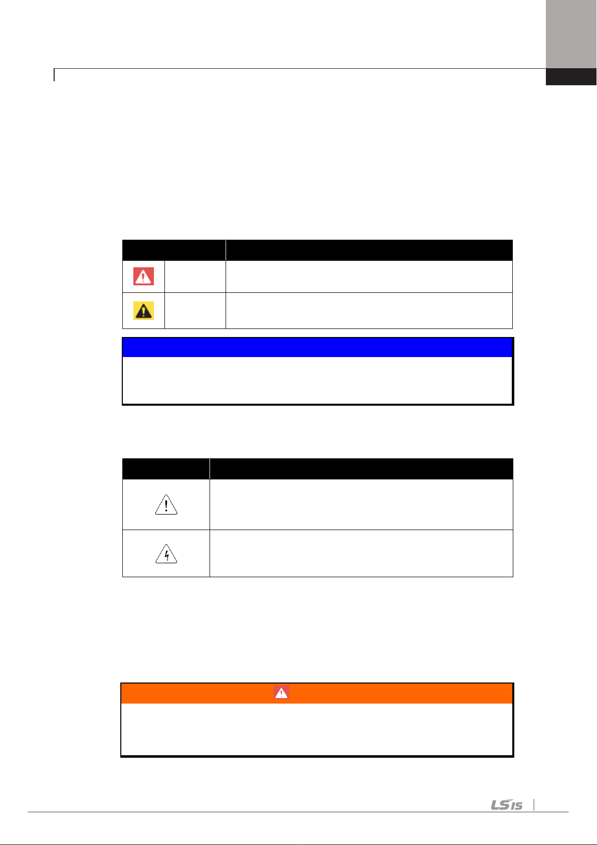
WARNING
WARNINGWARNING
WARNING
Do not run the inverter with the front cover removed.
Otherwise, you may get an electric shock due to high voltage termi-
nals or charged capacitor exposure.
Do not remove the cover except for periodic inspections or wir-
ing, even if the input power is not applied.
Otherwise, you may access the charged circuits and get an electric
shock.
Wiring and periodic inspections should be performed at least
10 minutes after disconnecting the input power and after
checking the DC link voltage is discharged with a meter (below
DC 30V).
Otherwise, you may get an electric shock.
Operate the switches with dry hands.
Otherwise, you may get an electric shock.
Do not use the cable when its insulating tube is damaged.
Otherwise, you may get an electric shock.
Do not subject the cables to scratches, excessive stress,
heavy loads or pinching.
Otherwise, you may get an electric shock.
CAUTION
CAUTIONCAUTION
CAUTION
Install the inverter on a non-flammable surface. Do not place
flammable material nearby.
Otherwise, fire could occur.
Disconnect immediately the input power if the inverter gets
damaged.
Otherwise, it could result in a secondary accident and fire.
After the input power is applied or removed, the inverter will
remain hot for a couple of minutes.
Otherwise, you may get bodily injuries such as skin-burn or dam-
age.
Do not apply power to a damaged inverter or to an inverter with
parts missing even if the installation is complete.
Otherwise, electric shock could occur.
Do not allow lint, paper, wood chips, dust, metallic chips or
other foreign matter into the drive.
Otherwise, fire or accident could occur.