Power Master SI Series User manual
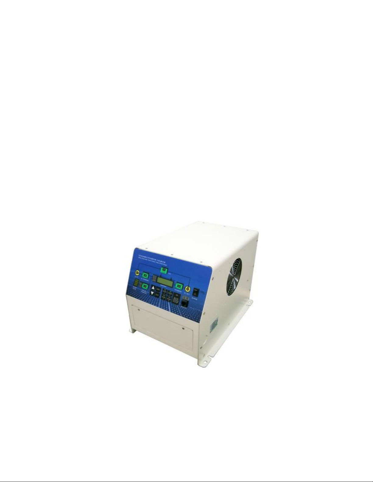
Stackable Inverter (SI series)
By Power Master
Sine Wave Inverter / ATS / Battery Charger /
Solar Charge controller (optional)
More Inverters stackable
3Phase connectable
USER MANUAL
USER MANUALUSER MANUAL
USER MANUAL

2
CONTENTS
Introduction .............................................................................................................................4
Specification ..............................................................................................................................7
Dimension ..................................................................................................................................9
Chapter 1 Installation .............................................................................................................11
1.1 Box Contents ..................................................................................................11
1.2 Location..........................................................................................................11
1.3 Requirements .................................................................................................11
1.4 Connection of Battery Cables ........................................................................12
1.5 Connection of AC Cabling .............................................................................12
1.6 Optional Connections.....................................................................................13
1.7 Grounding ......................................................................................................14
1.8 Remote Control Panel (RCP-4) .....................................................................14
Chapter 2 Settings...................................................................................................................15
2.1 Four Control Modes Applicatioin ...................................................................15
MODE 1: AC Power as Priority Support .......................................................15
MODE 2: AC Generator Support with Dynamic Power Shifting..................18
MODE 3: Renewable Energy with Power Support ........................................20
MODE 4: Renewable Energy with AC Charger Backup Support.................23
Chapter 3 Wiring ....................................................................................................................25
3.1 Optional Fan Cover Application ...................................................................25
3.2 Upper-Front Panel Display............................................................................26
3.3 Lower-Front Panel Display............................................................................29
3.4 Battery Connection ........................................................................................30
3.5 Parallel Connection Schematic ......................................................................32
3.6 3-Phase Connection Schematic ......................................................................33
3.7 3-Phase System 15 Modules ...........................................................................34
Capter 4 User Constants .........................................................................................................35
4.1 Structure of User Constants ..............................................................................36
4.2 Operation Flow ..................................................................................................40

3
Chapter 5 Constants List ........................................................................................................48
U Group: Monitor..................................................................................................48
A Group: Initialize.................................................................................................49
B Group: General ..................................................................................................49
C Group: Inverter..................................................................................................50
D Group: Charger .................................................................................................50
E Group: Aux-Relay..............................................................................................51
F Group: Solar Charger ........................................................................................56
O Group: Operator................................................................................................56
Chapter 6 Programming Constants .......................................................................................62
A Group: Initialize.................................................................................................62
B Group: General ..................................................................................................64
C Group: Inverter..................................................................................................71
D Group: Charger .................................................................................................73
E Group: Aux-Relay..............................................................................................76
O Group: Operator................................................................................................82
U Group: Monitor..................................................................................................84
Chapter 7 Trouble Shooting Table.........................................................................................90

4
Introduction
General
Feature
The “Stackable Inverter” is a 3 in 1 multi-function module unit – True Sine Wave Inverter
built in programmable Battery Charger and Auto Transfer Switch (ATS). Besides these
primary functions, however, the Stackable Inverter has several advanced features that
provide a range of new applications as outlined below:
Uninterrupted Power deliver
In the event of a grid failure, or shore or generator power being disconnected, the inverter
within the Stackable Inverter is automatically activated and takes over supply to the
connected loads. This happens so fast (less than 10 milliseconds) that computers and other
electronic equipment will continue to operate without disruption.
More inverters stackable
Virtually unlimited power thanks to parallel operation up to 5 units can operate in parallel to
achieve higher power output. Five PM-3000SI-242 units, for example, provide 15kW of
output power with 350A charging capacity.
3 Phase connectable
In addition to parallel connection, three units of the same model can be configured for
three-phase output. But that’s not all: up to five sets of three units can be parallel connected
for a huge 45kW inverter and 1050A charger!
Power Control-Dealing with limited generator or shore side power
The “Stackable Inverter” is a very powerful battery charger. It will therefore draw a lot of
current from the generator or shore side power. A maximum generator or shore current can
be set (B2-05). The “Stackable Inverter” will then take account of other AC loads and use
whatever is extra for charging thus preventing the generator or shore supply from overload.
Power Assist-Boosting the capacity of shore or generator power
This feature takes the principle of Power Control to a farther dimension allowing the
“Stackable Inverter” to supplement the capacity of the alternative source. Where peak
power is so often required only for a limited period; it is possible to reduce the size of
generator needed or conversely enable more to be achieved from typically limited shore
connection. When the load reduces, the spare power is used to recharge the battery.

5
Battery Charger
Adaptive 4-stage charge characteristic: Bulk-Absorption-Float-Equalize
The “Stackable Inverter” features a microprocessor controlled “adaptive” battery
management system that can be preset to suit different types of batteries. The “adaptive”
feature will automatically optimize the process relative to the way the battery is being used.
The right amount of charge: Variable Absorption Time
When only shallow discharges occur (a yacht connected to shore power for example), the
absorption time is kept in order to prevent overcharging of the battery. After a deep
discharge, the absorption time is automatically increased to make sure that the battery is
completely recharged.
Preventing damage due to excessive gassing: The Battery Safe Mode
If, in order to quickly charge a battery, a high charge current in combination with a high
absorption voltage has been chosen. The “Stackable Inverter” will prevent damage due to
excessive gassing by automatically limiting the rate of voltage increase once the gassing
voltage has been reached.
Less maintenance and aging when the battery is not use: The Equalize Mode
The equalize mode kicks in whenever the battery has not been subjected to discharge during
24 hours. In the equalize mode, float voltage is reduced to 2.2V/cell (13.2V for 12V battery)
to minimize gassing and corrosion of the positive plate. One a week, the voltage is raised
back to absorption level to “equalize” the battery. This feature prevents stratification of the
electrolyte and sulphation, a major cause of early battery failure.
2 outputs to charge 2 battery banks
The “Stackable Inverter” features 2 outputs, of which 1 can carry the full output current.
The second output, limited to approximately 4A and with a slightly lower output voltage, is
intended to top up a starter battery.
To increase battery life: Temperature Compensation
Every “Stackable Inverter” comes with a battery temperature sensor (BTS-3) when
connected, charge voltage will automatically decrease with increasing battery temperature.
This feature is especially recommended for sealed batteries and/or when important
fluctuation of battery temperature is expected.

6
Battery Voltage Sense
In order to compensate for voltage loss due to cable resistance, the “Stackable Inverter” is
provided with a voltage sense facility so that the battery always receives the correct charge
voltage.
Extensional Solar Charger
Stackable Inverter also provides the availability of up to 10 sets of Solar Charger, PM SCC
45A or PM SCC 60A (optional) to be used with solar panel to charge the battery. Stackable
Inverter sends the 4-stage charging command to extensional Solar Charger via port C
(Extension Port) for the best quality of solar charging.

7
Specification
MODEL
12 Volt System
24 Volt System
48 Volt System
PM-1500SI-12X (1)
PM-1500SI -24X
PM-1500SI -48X
PM-3000SI -12X (1)
PM-3000SI -24X
PM-3000SI -48X
GENERAL
Ventilation Forced cooling Forced cooling
Temperature
–Operation
–Storage
-20℃~ +70℃
-25℃~ +80℃
-20℃~ +70℃
-25℃~ +80℃
Protection
a. Output short circuit ˇˇ
b. Over load ˇˇ
c. Battery voltage too high ˇˇ
d. Battery voltage too low ˇˇ
e. DC voltage ripple too high ˇˇ
f. Temperature Sensor
Transformer ˇ(105℃)ˇ(105℃)
Electronic & Powerstage ˇ(70℃)ˇ(70℃)
BTS-3 ˇ(50℃)ˇ(50℃)
Humidity 0~95% (non condensing) 0~95% (non condensing)
Power control Function ˇˇ
Power assist Function ˇˇ
Uninterrupted AC power ˇ (less than 10 msec) ˇ (less than 10 msec)
Adaptive 4-stage charge ˇˇ
Two output to charge 2 battery banks ˇˇ
Auxiliary Relay X 3 X 3
Parallel operation ˇ(Max. 5 sets) ˇ(Max. 5 sets)
3-phase capacity ˇˇ
Battery voltage sensor ˇˇ
Battery Temperature sensor (BTS-3) ˇˇ
Remote control port ˇˇ
Extension Port (Port C) ˇˇ
INVERTER
Input Voltage Range (VDC) 9.5 -16V / 19-32V / 38-64V
Output Voltage (VAC) 185~240 VAC / 90~120 VAC
Output Frequency 50Hz /60Hz ± 0.1%
Output Waveform Pure sinewave

8
(1) X should be 1, output voltage = 90~120 VAC or 2, output voltage = 185~240 VAC
Output Voltage THD <5%
Power Factor (All Loads) ˇ
No linger load, crest factor 3: 1
Cont. Power Output (W)
Under 70℃(cosθ=1.0)
1500W
(No derate)
3000W
(No derate)
Cont. Power Output (W)
Over 70℃(cosθ=1.0)
0W
(Shutdown)
0W
(Shutdown)
Maximum Power (W) 3000W 6000W
Maximum Efficiency (%) 82/84/85 84/86/89
Zero-load Power (W) 12W 18W
CHARGER
Input Voltage Range (VAC) 200~250 VAC / 100~125 VAC
Input Frequency 45-55Hz /55-65 Hz
Power Factor 1
Charge Characteristic 4-stage adaptive / Bulk-Absorption-Float-Equalize
Maximum DC Voltage Ripple (Vrms) < 1.25 V
Charge Current House Battery (A) 70A/40A/20A 140A/70A/40A
Charge Current Starter Battery (A) 4A
Absorption Voltage Default (VDC) 14.4V / 28.8V / 57.6V
Float voltage Default (VDC) 13.8V / 27.6V / 55.2V
Equalize Voltage default (VDC) 13.2V / 26.4V / 52.8V
Output Charge Voltage (min ~ max) 8V~16V / 11V~32V / 22V~64V
Battery Temperature sensor BTS-3
AC INPUT SWITCH
AC IN Terminal Circuit Breaker 15A (120V) /15A (230V) 30A (120V) /15A (220V)
Switch-over Time
a. inverter to AC input 0 msec.
b. AC input to inverter 0 msec.
Detection Time AC Input Fault 4 ~10 msec.
Trip Level AC Input to Inverter 90 VAC / 180 VAC
Trip Level Inverter to AC Input 94 VAC / 187 VAC
Min.~ Max. Frequency Range 45-55 Hz / 55-65 Hz
MECHANICAL
Cabinet / Protecting Class Aluminum / IP20
Dimension (HXWXD) 362 x 258 x 370 mm 424 x 258 x 370 mm
Weight (kgs) 30 kgs 35 kgs

9
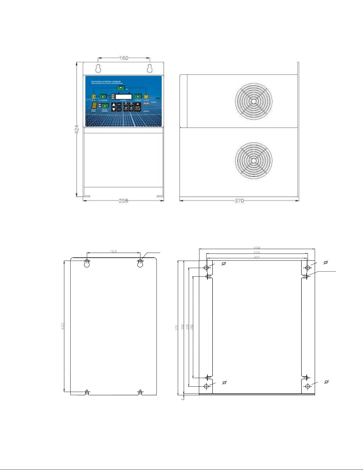
Dimension
PM-1500SI-12/24 Unit: mm
Installation Holes
Backside Mounting Holes Bottom Mounting Holes
1 0
10
10
1 0 M 6 -4
M8-4
10
PM-3000SI-12/24 Unit: mm
Installation Holes
Backside Mounting Holes Bottom Mounting Holes
1 0
10
10
1 0 M 6 -4
M8-4

11
Chapter 1 Installation
This product should be installed by a qualified electrician.
1.1 Box Contents
Stackable Inverter
USER MANUAL
Bag Containing connection items, ie:
Battery Temperature Sensor (BTS-03)
Four M8 nuts (including spring washers)
Four terminals and casing
1.2 Location
The product must be installed in a dry and well-ventilated area, as close as possible to
batteries. There should be a clear space of at least 20 cm around the appliance for cooling.
Excessively high ambient temperature will result in the following
Reduced service life
Reduced charge current
Reduced peak capacity or shutdown of the inverter
Never position the appliance directly above the batteries.
The product is suitable for wall mounting. The back and the bottom of the enclosure has
holes for wall mounting purposes, see Page 9 and 10.
The appliance can be mounted horizontally as well as vertically; vertical mounting is
preferable. Te vertical position offers optimum cooling.
The interior of the product must remain accessible after installation. Ensure the AC
and DC input cables are fitted with fuses and circuit breakers. Try and keep the
distance between the product and battery to a minimum in order to minimize cable
voltage losses.
For safety purpose, this product should be installed in a heat-resistant environment if
it is used with equipment where a substantial amount of power is to be converted. You
should prevent the presence of e.g. chemicals, synthetic components, curtains or
textiles, etc. in the immediate vicinity.
1.3 Requirements
Screwdrivers for removing the lower-front panel and connecting AC loads.
2 battery cables (maximum length 6 meters)
12
Including battery terminals and cable ends.
Insulated box spanner (13 mm) for securing the DC terminal nuts.
Three-wire cable for AC cabling.
1.4 Connection of Battery Cables
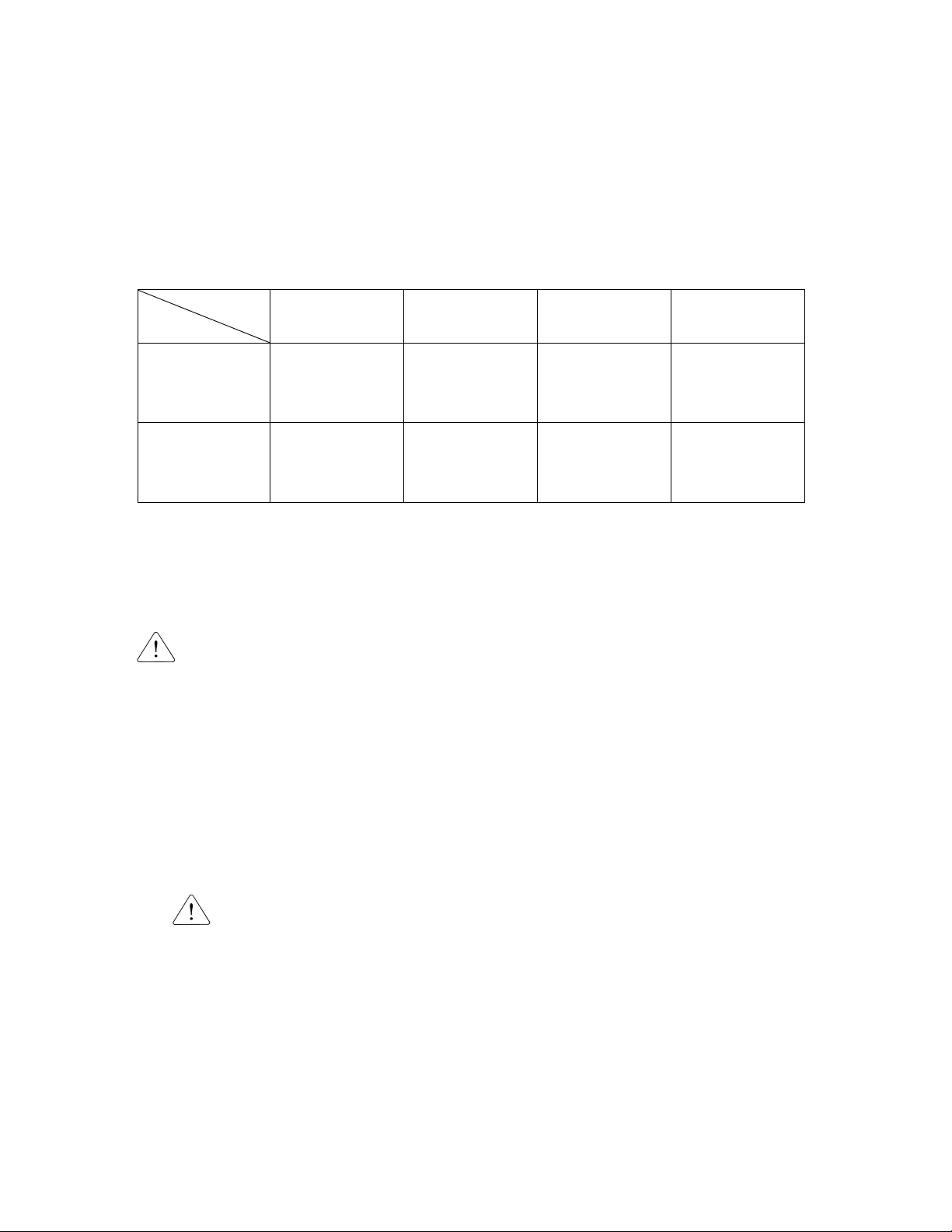
In order to fully utilize the full capacity of the product, batteries with sufficient capacity and
battery cables with sufficient cross section should be used, please see table:
Model
Item PM-1500SI-12X
PM-1500SI-24X
PM-3000SI-12X
PM-3000SI-24X
Recommended
battery capacity
(Ah)
200~700 100~400 400~1200 200~700
Recommended
cross section
(mm2)(0~6m)
50 mm238 mm280 mm250 mm2
Remark: Internal resistance is the important factor when working with low capacity batteries.
Consult your supplier.
Procedure:
Proceed as follows to connect the battery cables:
Use an insulated box spanner in order to avoid shorting the battery.
Avoid shorting the battery cables:
Undo the four screws at the lower-front panel of the enclosure and remove the panel.
Connect the battery cable: the + (red) on the right and the – (black) on the left. Please
see page 30 and 31.
Don’t reverse the (+) and (-) of the battery. This may cause internal damage.
Tighten the connections after positioning the fastening items supplied with product.
Secure the nuts tightly in order to reduce the contact resistance as much as possible.
1.5 Connection of AC Cabling
The enclosure must be grounded for safety purpose. An earth screw has been fitted at
the bottom side of the enclosure.
The terminal block can be found at lower-front panel of the enclosure: The shore or mains
(AC IN) cable must be connected to AC IN terminals, use a three-wire cable and a cross
section of 4~10 mm2.
Procedure:
Proceed as follows to connect the AC cables.
The AC output cable can be connected directly to terminal block containing the word

13
“AC OUT”. The terminal points are indicated clearly. From left to right: “G” (earth),
“N” (neutral), and “L” (phase).
The AC input cable can be connected to the terminal block containing the word “AC
IN”, the terminal points are indicated clearly from left to right “L” (phase), “N”
(neutral), and “G” (earth).
The current which is switched through to the output (AC OUT) is not fused.
External fuses or current limiters have to be installed.
1.6 Optional Connections
A number of operational connections are possible:
1.6.1 Second Battery
The “Stackable Inverter” has a connection for charging a starter battery.
For connection, see page 29.
1.6.2 Voltage Sense
Two sense wires may be connected to compensate possible battery cable losses during
charging. Use wires of at least 0.75 mm2. For connection, see page 29.
1.6.3 Battery Temperature Sensor (BTS-3)
The battery temperature sensor supplied with the product may be used for temperature
compensated charging, see page 29.
The sensor is insulated and must be mounted on the batteries minus pole.
1.6.4 3 Sets of Auxiliary Relay (RY1, RY2, RY3) Output
The “Stackable Inverter” provides 3 sets of Auxiliary Relays for users to connect to
other appliances or to output the alarm signals. 3 sets of relays can be programmed for
respective function. (E Group Constants) and can be practically applied which is one of
the greatest features.
1.6.5 Parallel Connection
The product can be connected in parallel using several identical modules, please see
page 32. The batteries must be connected in accordance with page 32.This requires
interconnecting the products with the package of a special box, parallel box, to be
supplied by factory in conjunction with a connection diagram.
Parallel connection requires compliance with the following conditions:
1. No more than 5 units should be connected in parallel.
2. Only identical models should be connected in parallel.
3. Ensure sufficient battery capacity is available.
4. The prescribed cable cross sections (between battery and distribution point) must
be multiplied with the number of appliances to be connected in parallel.
5. Position the products close to each other but ensure there is adequate clearance for
ventilation minimum 20 cm. For better ventilation, please install the fan cover

14
(optional).
6. The BTS, voltage sensor and remote control panel (RCP) must be connected to
Master.
7. The cables for each appliance must be equal in length (AC and DC)
1.6.6 3-Phase Operation
The product can also be used in a 3-phase system, see page 33. The batteries must be
connected in accordance with page 33. The following condition conditions should be
complied with in the case of 3-1phase operation:
1. Only identical models should be used.
2. Ensure sufficient battery capacity is available.
3. Position the products close to each other but ensure there is adequate clearance for
ventilation minimum 20 cm.
(For the better ventilation environment, it is highly recommended to install the fan
cover in the air-in on the right side of Stackable Inverter.
4. The BTS, voltage sensor should preferably be connected all three units (1 Master
unit and 2 Follower units).
5. Only a single remote control can be connected.
1.7 Grounding
When the input voltage of the Stackable Inverter is not switched through, the neutral of “AC
OUT” is connected to ground by means of a relay. This function can be disabled by constant
B2-07 (B2-07=0 Disconnect)
1.8 Remote Control Panel (RCP-4)
The product can be operated remotely from remote port with the aid of a remote control
panel. For connection of a remote control panel, see page 28.
Note: The display panel and operation flow of the remote control panel is exactly the same as
the upper-front display panel.

15
Chapter 2 Settings
Settings may only be changed by a qualified engineer.
Carefully read the user manual before any change is made.
When setting the charger, all connections to the battery must be disconnected from the
Stackable Inverter.
Do not use non-rechargeable batteries.
Batteries should be placed in a dry and well-ventilated area during charging.
The product default settings are for charging gel batteries. For the recommended battery
voltage initial settings, see D1 (Charger) Group parameters.
2.1 Four Control Modes Applications
MODE 1: AC Power as Priority Support (Example of PM-3000SI-242)
When Stackable Inverter enters to MODE 1, B2-09 (AC IN DynaCur Limit)=0 (Disable) and
the value of B2-18 (MODE1: ACINCurrent Lmt) will be loaded to B2-05.
1. INVERTER Mode:
When AC IN=0 A, AC OUT load is completely supplied by INVERTER. It goes to the
inverter mode.
Battery
Grid,Shore,G enerator
Power Load
ATS O FF
AC IN AC O UT
5A
5A
0A
75A

16
2. Power Control Mode (a)
In this example:
All AC loads are off, with the “Stackable Inverter” constant B2-05=5A (AC IN Current
Limit),
the AC CHARGER will not take more than 5A with limits to battery charge current to
75A.
3. Power Control Mode (b)
Now some small loads are switched on and load increase to 3A. Only 5-3=2A is left to
charge the batteries and charge current is reduced to about 30A.
※ Note: Shore current is automatically limited to 5A and the AC input circuit
breaker will not trip!
Battery
Shore Power
M ax 5A Load
ATS ON
AC IN AC OUT
5A
5A
0A
75A
5A
B2-05=5A

17
Battery
Shore Power
Max 5A Load
ATS ON
AC IN AC OUT
5A
2A
30A
5A
B2-05=5A
3A

18
4. Power Control Mode (c)
The load is switched on and current consumption increase to 5A. Nothing is left to charge
the battery.
The charge current is automatically reduced to 0A, and the AC input circuit breaker does
not trip!
Battery
Shore Power
Max 5A Load
ATS ON
AC IN AC OUT
5A
0A
5A
B2-05=5A
5A
5. Power Assist Mode
And now the other load adds and switches on and the current increases to 11A. This is
where Power Assist is needed.
The bidirectional converter starts operating as inverter to add 6A to the 5A that is
available from the shore-side: Total 6+5=11A, and no overload on the AC supply.
As soon as the load reduces to less than 5A, any current that is left over will be used to
recharge the battery.
Battery
Shore Power
Max 5A Load
ATS ON
AC IN AC OUT
5A
6A
5A
B2-05=5A
11A
90A

19
MODE 2: AC Generator Support with Dynmaic Power Shifting
(Example of PM-3000SI-242)
When Stackable Inverter enters to MODE 2, B2-09(AC IN DynaCur Limit)=1 (Enable) and
the value of B2-21 (MODE 2: ACINCurrent Lmt) will be loaded to B2-05.
1. INVERTER Mode:
When AC IN=0 A, AC OUT load is completely supplied by INVERTER. It goes to the
inverter mode.
Battery
Grid,Shore,Generator
Power Load
ATS OFF
AC IN AC OUT
5A
5A
0A
75A
2. Power Control Mode (a)
In this example:
All AC loads are off, with the “Stackable Inverter” constant B2-05=5A (AC IN Current
Limit),
the AC CHARGER will not take more than 5A with limits to battery charge current to
75A.
Battery
Shore Power
Max 5A Load
ATS ON
AC IN AC OUT
5A
5A
0A
75A
5A
B2-05=5A

20
3. Power Control Mode (b)
Now some small loads are switched on and load increase to 3A. Only 5-3=2A is left to
charge the batteries and charge current is reduced to about 30A.
※ Note: Shore current is automatically limited to 5A and the AC input circuit
breaker will not trip!
Battery
Shore Power
Max 5A Load
ATS ON
AC IN AC OUT
5A
2A
30A
5A
B2-05=5A
3A
4.Power Control Mode (c)
The load is switched on and current consumption increase to 5A. Nothing is left to charge
the battery.
The charge current is automatically reduced to 0A, and the AC input circuit breaker does
not trip!
Battery
Shore Power
Max 5A Load
ATS ON
AC IN AC OUT
5A
0A
5A
B2-05=5A
5A
This manual suits for next models
6
Table of contents
Other Power Master Inverter manuals


