Kusam-meco KM 2803IN User manual

80
G-17, Bharat Industrial Estate, T. J. Road, Sewree (W), Mumbai - 400 015. INDIA.
Sales Direct.: 022 -24156638, Tel. : 022-241224540, 24181649, Fax : 022 - 24149659
An ISO 9001:2008 Company
All Specifications are subject to change without prior notice
Navin.com/D.drive/sandeep gupta/New catlog Dec 2011/KM-2803IN.cdr
®
An ISO 9001:2008 Company
®
AL-30 TestLeadAL-50 TestLead standard
HIGH VOLTAGE 5 KV
DIGITAL INSULATION RESISTANCE TESTER
Model- KM - 2803IN - 5KV DC
ELECTRICAL SPECIFICATIONS: KM 2803IN
LCD DISPLAY
SPECIAL FEATURES :
?Microprocessor controlled with
advanced safety features.
?2 lines X 16 Characters large
LCD display.
?Bar-graph indicates test voltage-rise
& decay can be observed during tests.
?Display and sound warning if external
voltage is present.
?Continuous battery monitoring.
?Auto-ranging / Auto Power-off.
TM
?Battery life is extended by “Enersave ” feature.
?Built-in carrying case. Test leads in separate
pouch.
?Large LCD Show test time duration (up to 99.9s)
for Easy Comparison.
?IEC 1010-1 CAT III 300V.
0.5 KV
0-25GW
2.5 KV
1 KV
0-50GW0-125GW
5 KV
0-250GW
Test Voltage (DCV)
Measuring Ranges
(Auto-Range)
0-50GW: ± 3% of reading
50-250GW: ± 5% of reading
Accuracy
170(L)x120(W)x95(D) mm.
Dimensions
1.5V (AA) x 8 Alkaline Batteries
Power Source
Test leads-AL-50 (3 meter), AL-30 (1.25 meter),
AL-30C (1.25 meter), Shoulder belt (BET-2800),
Instruction Manual, Batteries
Accessories
930gApprox.
Weight (battery included)
Pollution Degree 2
Altitude upto 2000 meter
Operating Temperature & Humidity 0 ~ 40°C; 80% max. R.H.
Storage Temperature & Humidity -10°C ~ 65°C; £ 80% R.H.

80
G-17, Bharat Industrial Estate, T. J. Road, Sewree (W), Mumbai - 400 015. INDIA.
Sales Direct.: 022 -24156638, Tel. : 022-241224540, 24181649, Fax : 022 - 24149659
An ISO 9001:2008 Company
All Specifications are subject to change without prior notice
Navin.com/D.drive/sandeep gupta/New catlog Dec 2011/KM 2804IN.cdr
®
LCD DISPLAY
SAFETY :
An ISO 9001:2008 Company
®
AL-30 TestLeadAL-50 TestLead standard
ELECTRICAL SPECIFICATIONS: KM 2804IN
1 KV 5 KV
2.5 KV
0-50GW0-125GW
10 KV
0-500GW
Test Voltage (DCV)
Measuring Ranges
(Auto-Range)
0-50GW: ± 3% of reading
50-500GW: ± 5% of reading
Accuracy
170(L)x120(W)x95(D) mm.
Dimensions
1.5V (AA) x 8 Alkaline Batteries
Power Source
Test leads-AL-50 (3 meter), AL-30 (1.25 meter),
AL-30C (1.25 meter), Shoulder belt (BET-2800),
Instruction Manual, Batteries
Accessories
930gApprox.
Weight (battery included)
Pollution Degree 2
Altitude upto 2000 meter
Operating Temperature
& Humidity 0 ~ 40°C; 80% max. R.H.
0-250GW
Storage Temperature
& Humidity -10°C ~ 65°C; £ 80% R.H.
HIGH VOLTAGE 10KV
DIGITAL INSULATION RESISTANCE TESTER
Model- KM 2804IN - 10KV DC
CE marking according to the Low Voltage Directive (2006/95/EC) and EMC Directive
(2004/108/EC, 92/31/EEC, & 93/68/EEC) and found to comply with the
essential requirement of the directives.
IEC/EN 61010-1: 2001. EN 61326-1, EN 55011+A1+A2, EN 61000-3-2+A2,
EN 61000-3-3+A1+A2, EN 61000-4-2+A1+A2, EN 61000-4-3+A1,
EN 61000-4-4, EN 61000-4-5+A1, EN 61000-4-6+A1, EN 61000-4-8+A1,
EN 61000-4-11, EN61000-4-6+A1, EN61000-4-11.

HIGH VOLTAGE DIGITAL INSULATION TESTER
MICROPROCESSOR CONTROLLED
KUSAM-MECO
Model 2803 IN
Insulation Tester
AUTORANGING
AUTO-OFF
!
5kV
ON / TEST
2.5kV 1kV 500V
DO NOT USE
ON LIVE SYSTEM
HIGH VOLTAGE DIGITAL INSULATION TESTER
MICROPROCESSOR CONTROLLED
AUTORANGING AUTO-OFF
!
10kV
ON / TEST
5kV 2.5kV 1kV
DO NOT USE
ON LIVE SYSTEM
G-17,Bharat Industrial Estate,
T.J.Road, Sewree(W),
Mumbai-400 015.(INDIA)
Sales Direct : 91-22-24156638
Tel : 91-22-2412 4540, 2418 1649
Fax : 91-22-2414 9659
Website: www.kusamelectrical.com , www.kusam-meco.co.in
www.kusam-meco.co.in
OPERATION MANUAL
HIGH VOLTAGE INSULATION
RESISTANCE TESTER
KUSAM-MECO
Model 2804 IN
Insulation Tester

Safety.............................................................................1
Models............................................................................3
Features.........................................................................4
Specifications.................................................................5
Instrument Layout..........................................................6
Functions.......................................................................8
Preparation for Measurement........................................11
Battery & Fuse Replacement.........................................11
Calibration.....................................................................11
Servicing........................................................................11
Cleaning & Storage.......................................................11
Insulation Resistance Testing........................................12
Test Certificate...............................................................14
Warranty.........................................................................15
CONTENTS
Page No.Title
1
IMPORTANT!
1. Safety Precautions.
Therefore it is extremely important that you read the following information
before using your Digital Insulation Tester.
1.1 This Instrument must only be used and operated by a competent trained
person and in strict accordance with the instructions. KUSAM-MECO will
not accept liability for any damage or injury caused by misuse or non
compliance with instructions and safety procedures.
1.2 This instrument must not be used on live circuits. Ensure all circuits are
de-energised before testing See paragraph1.8 for details of built-in
warning features should your Digital Insulation tester be connected to
a live system.
1.3 Never open Digital Insulation Tester except for battery replacement.
(See Battery replacement section).
1.4 Always inspect your Digital Insulation tester and test leads before use for
any sign of abnormality or damage. If any abnormal conditions exist (broken
test leads, cracked case, display faulty etc...). Do not attempt to take any
measurement or use the tester, Return your digital Insulation tester
to KUSAM-MECO or your nearest distributor for service.
1.5 Never replace the protective fuse with any other than the specified or
approved equivalent.
1.6 Your Digital Insulation tester has been designed with your safety in mind.
However, no design can completely protect against incorrect use.
Electrical circuits can be dangerous and /or lethal when a lack of caution
or poor safety practice is used. Use caution in the presence of voltage above
24V as these pose a shock hazard.
1.7 Pay attention to cautions and warnings which will inform you of potentially
dangerous procedures.
1.8 Your Digital Insulation Tester has a live circuit warning beeper if it is
connected to a live circuit, a rapid pulsating bleep will be heard. DO NOT
proceed to test and immediately disconnect the instrument from the circuit. In
addition your tester will display the warning message.
Electricity can cause severe injuries even with low voltages or currents.

2
1.9 Rated environmental conditions:
1.9.1 Indoor use.
1.9.2 Pollution Degree 2.
1.9.3 Altitude up to 2000 Meter.
19. 4 Relative Humidity 80% Max.
o
1.9.5 Ambient Temperature 0~40 c.
2.0 Observe the International Electrical Symbol listed below.
Warning! Risk of electric shock.
Caution ! Refer to this manual before using the meter.
!
3
2. Models
2.1
The 2803 IN is a four voltage(500V,1KV, 2.5 KV and 5 KV)
Digital Insulation Tester. Auto Ranging and Menu Driven.
The 2803 IN has a Bar-Graph which displays the voltage
decay during the discharge of the tested circuit and the
voltage stressing the insulation while the test is in
progress.
The 2803 IN has a Timer which shows the elapsed time
for which the test was”ON” and also shows the total time
of the test.
The 2803 IN displays a Voltage warning and sounds when
AC or DC is present before injecting the Test voltage.
The 2803 IN will buzz intermittently when high voltage is
generated and this remains until the circuit under test is
fully discharged.
The 2804 IN is a four voltage(1KV, 2.5KV, 5KV and 10KV)
Digital Insulation Tester. Auto Ranging and Menu Driven.
The 2804 IN has a Bar-Graph which displays the voltage
decay during the discharge of the tested circuit and the
voltage stressing the insulation while the test is in
progress.
The 2804 IN has a Timer which shows the elapsed time
for which the test was”ON” and also shows the total time
of the test.
The 2804 IN displays a Voltage Warning and sounds .
when AC or DC is present before injecting the Test
Voltage.
The 2804 IN will buzz intermittently when high voltage is
generated and this remain until the circuit under test is
fully discharged.
2803 IN
2804 IN
2.2

4
EARTH
3. FEATURES
•2 Lines X 16 Characters large L.C.D.
•Four Insulation Test Voltage
2803 IN
500VDC - 25000MW
1000VDC - 50000MW
5000VDC - 250000MW
2500VDC - 125000MW
2804 IN
1000VDC - 50000MW
2500VDC - 125000MW
10000VDC - 500000MW
5000VDC - 250000MW
• Insulation Resistance Autoranging on all range.
TM.
• ENERSAVE
• Bar-graph indicates test voltage-rise and decay can be observed
during tests
• Warning and display of external voltage presence.
• Over load protected.
• Low battery indicator.
• Measure Insulation Timer Test.
• Very Low Battery Consumption.
• Smart Microprocessor controlled.
• One years Warranty.
• Better than 5% accuracy.
• Auto- Off.
• Compact and Light weight.
4. CONNECTIONS
!
+++
INSULATION
CABLE CORE OUTER
SHEATING COVERING
GUARD
0V
LINE
5
5. SPECIFICATIONS
Test Voltage 500VDC 1KV DC 2.5KV DC 5KV DC
25GW50GW250GW125GW
Measuring
Auto
Ranging
Range
Accuracy ± 5% ± 2 Digits
Power 8 x 1.5V
Alkaline Battery
2803 IN
Measuring
Auto
Ranging
Range
Test Voltage 1kVDC
50GW125GW500GW250GW
2.5kVDC 5kV DC 10kV DC
Accuracy ± 5% ± 2 Digits
Power 8 x 1.5V
Alkaline Battery
2804 IN

67
HIGH VOLTAGE DIGITAL INSULATION TESTER
MICROPROCESSOR CONTROLLED
AUTORANGING AUTO-OFF
!
5KV
ON / TEST
2.5KV 1KV 500V
DO NOT USE
ON LIVE SYSTEM
123 4 5
66
HIGH VOLTAGE DIGITAL INSULATION TESTER
MICROPROCESSOR CONTROLLED
AUTORANGING AUTO-OFF
!
10KV
ON / TEST
5KV 2.5KV 1KV
DO NOT USE
ON LIVE SYSTEM
123 4 5
.On Switch. Test Button Switch
1
ENERSAVE TM
2.- 5000V Test Selection Button
3- 2500V Test Selection Button
4- 1000V Test Selection Button
5- 500V Test Selection Button
6- ENERSAVE TM .Interlligent L.C.D.
1.On Switch. Test Button Switch
ENERSAVE TM
2.- 10000V Test Selection Button
3- 5000V Test Selection Button
4- 2500V Test Selection Button
5- 1000V Test Selection Button
6- ENERSAVE TM .Interlligent L.C.D.
KUSAM-MECO
Model 2803 IN
Insulation Tester KUSAM-MECO
Model 2804 IN
Insulation Tester
INSTRUMENT LAYOUT : MODEL-2803 INSTRUMENT LAYOUT : MODEL-2804

9
TM
The ENERSAVE Mode is default mode of the instrument
TM
The ENERSAVE Mode is enabled when pressing the
TEST button (1)for less than 3 seconds.
TM
The ENERSAVE Mode is disabled when pressing the
TEST button (1)for more than 3 seconds.
TM
When the ENERSAVE Mode is disabled, the instrument
Operates in continuous mode.
7. 8 Voltage Output Bar-Graph.
The Bar-Graph shows the voltage present on the leads
It also shows the voltage charging a cable or capacitive
system under test and shows the decay during the
Automatic Capacitive discharge of the system under test.
7. 9 Auto-Low Resistance Detect.
While in Insulation Test Mode, if the L.C.D. displays
“LOW MW,stop test immediately. This could mean that
the Insulation has breakdown and so you are now trying
to inject very h igh v oltage on a short circuit.
7.10 Timer
The duration of the test is shown on the L.C.D.
This is particularly useful to verify that insulation does not
break down within a certain time.
7.11 STOP Test
To stop the Test in progress, press the TEST button(1).
The test will immediately stop and the Instrument will
TM
enable the ENERSAVE mode Automatically.
7.12 Auto- Stop
Should the operator leave the Instrument in the test mode
TM
with the ENERSAVE disabled, the Instrument will
Automatically Stop the test after a duration of 99.9 Seconds.
(Auto -off still applies)
8
7. FUNCTIONS.
To switch your instrument “ON”, press the on button(1).
The L.C.D. will display the model, From then, Follow
Interactive instructions on L.C.D.
7.2 Insulation Resistance Measurement@ 10000Vdc. To select
10KV DC Test voltage, press 10KV button(2) (only available on
2804 IN)
7.3 Insulation Resistance Measurement@ 5KV DC. To select
5KV DC Test voltage, press 5KV button(2) on model 2803 IN
And(3) on model 2804 IN.
7.4 Insulation Resistance Measurement@ 2.5KV DC. To select
2.5KV DC Test voltage, press 2.5KV button(3) on model
2803 IN And(4) on model 2804 IN.
7.5 Insulation Resistance Measurement@ 1KV DC. To select
1KV DC Test voltage, press 1KV button(4) on model
2803 IN And(5) on model 2804 IN.
7.6 Insulation Resistance Measurement@ 500V DC. To select
500KV DC Test voltage, press 500V button(5) on model
2803 IN (only available on 2803 IN)
TM
7.7 ENERSAVE Mode
TM
The ENERSAVE Mode saves battery life by Automatically
turning the instrument to low Consumption(Reducing the Test
Duration).
7.1 Power-On

11
8.1 Before testing always check the following.
At Power “ON”, read the display to make sure the
“Replace Battery” message do not get displayed.
There is no visual damage to the instrument or test leads.
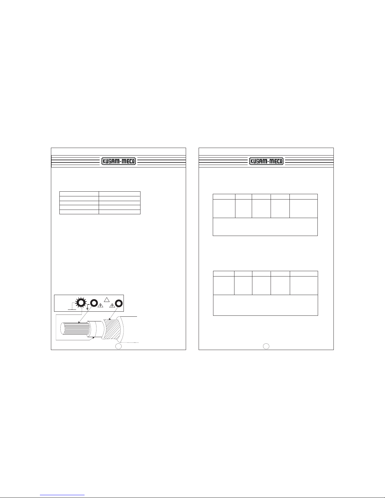
8.2 Test Leads continuity :
Using a Ohm-meter, check the resistance/ continuity of the
leads.
9. Battery Replacement.
9.1 Battery Replacement
Your Digital insulation Tester’s battery is situated under
TM
the tester. Your ENERSAVE display will indicate you
when battery need to be replaced.
Disconnect the test leads from the instrument, remove the
battery cover and the batteries.
Replace with 8 alkaline 1.5V R6 or L6 batteries, taking
care to observe correct polarity.
Replace battery Holder and the battery cover.
10. Calibration & Servicing
Both, calibration and servicing are performed at KUSAM-
MECO facilities.
Before returning the Instrument , ensure that:
·The leads have been checked for continuity and signs of
damage.
·The batteries are in good condition.
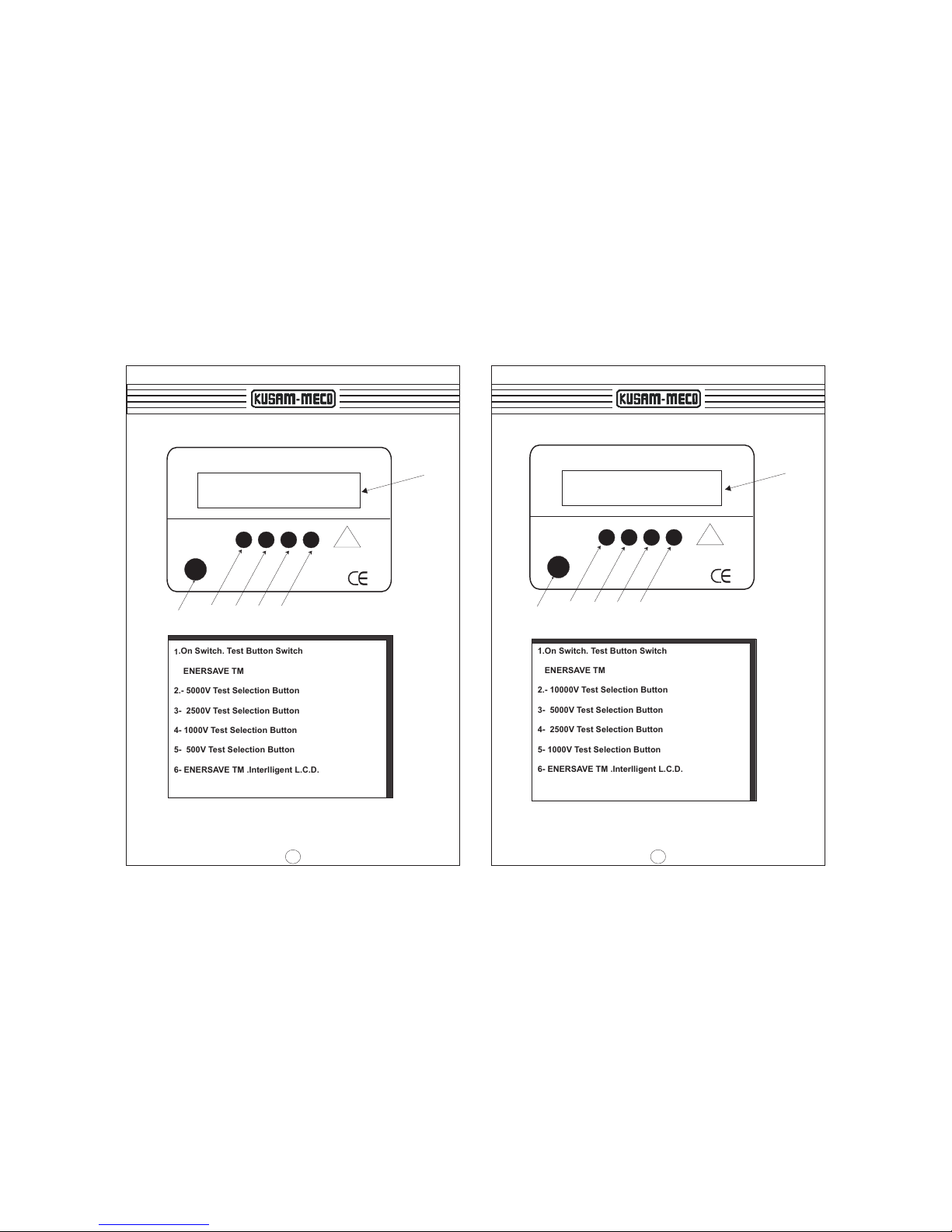
8. Preparation for Measurement
10
7.13 Auto Live / Voltage Warning.
Should the leads be placed onto a live system before
starting the test, a warning beeper will be automatically
activated and,
·Your instrument will display ”Live Warning..... Circuit Live”
Message.
Let the instrument discharge the circuit (in the case of
capacitive system) or make sure that the circuit under test is
not live.
7.14 Auto-Discharge.
At Auto-Stop or test completion, the Instrument Automatically
discharge the system under Insulation test, so that the
dangerous high voltage is discharged. The Auto-Discharge
can be observed on the L.C.D so that the operator only
removes for the leads when the discharge is complete.
During discharge, beep occurs so that the user does wait for
the complete discharge of the system under test.
This is indicated by a one second long beep accompanied by
the “HOLD” message on the display.
DO NOT REMOVE LEADS UNTIL THE HOLD MESSAGE
APPEARS ON THE DISPLAY.
7.15 “Replace Battery” Warning Indicator.
If the battery energy is detected to be too low, the instrument
will display the “Replace Battery” warning and Automatically
shut-down.The instrument can’t operate properly with a low
battery. Use only Alkaline batteries.
7.16 Auto-off
The Auto-off is announciated by a one second beep.
The Auto-off timer is automatically enabled
LIVE WARNING MESSAGE/BEEPER
To Clear Live Warning Message/Beeper
Remove leads from circuit under test and push
“TEST” button until display Clears
WARNING
To avoid electrical shock or damage to the
The meter, do not get water inside the case
11. CLEANING & STORAGE:
Periodically wipe the case with a damp cloth and detergent ;
do not use abrasives or solvents

12
12. INSULATION RESISTANCE TESTING WITH 2803 IN
Warning : Insulation test should be conducted on circuits that are
de-energised.
Ensure circuits are not live before commencing testing
Turn instrument “ON” by pressing the “ON” button.
The L.C.D. Display will come to the following screen.
Select Insulation test voltage .For example, 500V
The Following screen will confirm your selection.
If the system you are trying to Test is not voltage free,
the beep will go on. the following warning screen will appears.
Remove your leads immediately.
If the system is not live, the test will start and the following
screen will appear, indicating the test test ,duration and other
factors
If either the operator or the instrument stops the Test, the
latest result is “HOLD” on the L.C.D.The instrument
switches off after 45 to 60sec.
Select Test 5KV
2.5KV, 1KV, or 500V
500V 30000MW
Selected
Connect Leads,......
Testing for Live.
LIVE WARNING...
Circuit Live !!!
Follow the Interactive Screen.
R=1253.0MW85.2s
0 IIIIIIIIIIIIIII 500V
R=1253.0MW85.2s
0 HOLD 500V
2803 IN
13
13. INSULATION RESISTANCE TESTING WITH 2804 IN
Warning : Insulation test should be conducted on circuits that are
de-energised.
Ensure circuits are not live before commencing testing
Turn instrument “ON” by pressing the “ON” button.
The L.C.D. Display will come to the following screen.
Select Insulation test voltage .For example,10000V
The Following screen will confirm your selection.
If the system you are trying to Test is not voltage free,
the beep will go on, the following warning screen will
appears. Remove your leads immediately.
If the system is not live, the test will start and the following
screen will appear, indicating the test, duration and other
factors
If either the operator or the instrument stops the Test, the
latest result is “HOLD” on the L.C.D.The instrument
switches off after 45 to 60sec.
Select Test 10KV
5KV, 2.5KV, or 1KV
10KV 500000MW
Selected
Connect Leads,......
Testing for Live.
LIVE WARNING...
Circuit Live !!!
Follow the Interactive Screen.
R=125340MW85.2s
0 IIIIIIIIIIIIIII 10KV
R=125340MW85.2s
0 HOLD 10KV
2804 IN

14
MUMBAI
TEST CERTIFICATE
HIGH VOLTAGE INSULATION
RESISTANCE TESTER
This Test Certificate warrantees that the product has been
inspected and tested in accordance with the published
specifications.
The instrument has been calibrated by using equipment
which has already been calibrated to standards traceable
to national standards.
MODEL NO. ___________
SERIAL NO. ___________
DATE: ___________
ISO 9001
REGISTERED
QC
PASS
KUSAM-MECO
15
WARRANTY
Each “KUSAM-MECO” product is warranted to be free from defects in
material and workmanship under normal use & service. The warranty
period is one year (12 months) and begins from the date of despatch of
goods. In case any defect occurs in functioning of the instrument, under
proper use, within the warranty period, the same will be rectified by us free
of charges, provided the to and fro freight charges are borne by you.
This warranty extends only to the original buyer or end-user customer of a
“KUSAM-MECO” authorized dealer.
This warranty does not apply for damaged Ic’s, fuses, burnt PCB's,
disposable batteries, carrying case, test leads, or to any product which in
“KUSAM-MECO’s” opinion, has been misused, altered, neglected,
contaminated or damaged by accident or abnormal conditions of operation
or handling.
“KUSAM-MECO” authorized dealer shall extend this warranty on new and
unused products to end-user customers only but have no authority to
extend a greater or different warranty on behalf of “KUSAM-MECO”.
“KUSAM-MECO’s” warranty obligation is limited, at option, free of charge
repair, or replacement of a defective product which is returned to a
“KUSAM-MECO” authorized service center within the warranty period.
THIS WARRANTY IS BUYER’S SOLE AND EXCLUSIVE REMEDY AND
IS IN LIEU OF ALL OTHER WARRANTIES, EXPRESS OR IMPLIED,
INCLUDING BUT NOT LIMITED TO ANY IMPLIED WARRANTY OF
MERCHANTABILITY OR FITNESS FOR A PARTICULAR PURPOSE.
“KUSAM-MECO” SHALL NOT BE LIABLE FOR ANY SPECIAL,
INDIRECT, INCIDENTAL OR CONSEQUENTIAL DAMAGES OR
LOSSES, INCLUDING LOSS OF DATA, ARISING FROM ANY CAUSE
WHATSOEVER.
All transaction are subject to Mumbai Jurisdiction.
Table of contents
Other Kusam-meco Test Equipment manuals

Kusam-meco
Kusam-meco KM-CAL-907 User manual

Kusam-meco
Kusam-meco KM-CAL-801 User manual

Kusam-meco
Kusam-meco KM 36 User manual

Kusam-meco
Kusam-meco KM 66 User manual

Kusam-meco
Kusam-meco KM 3600 User manual

Kusam-meco
Kusam-meco KM-1520 User manual

Kusam-meco
Kusam-meco KM 1105ER User manual

Kusam-meco
Kusam-meco KM 7016 IN User manual

Kusam-meco
Kusam-meco KM-CAL-805 Installation manual

Kusam-meco
Kusam-meco KM-CAL-905 User manual