Calnex Paragon-X User manual

Paragon-X Getting Started Guide Page 1of 28

Paragon-X Getting Started Guide Page 2of 28
Notices
This document refers to Calnex Paragon-X GUI Software Revision X.10.39 and higher.
Last Updated: November 2018
© Copyright Calnex Solutions Ltd 2018. All rights reserved.
Reproduction, adaption, or translation without prior written consent is strictly prohibited, except as
allowed under the copyright laws.
Warranty
The information contained in this document is subject to change without notice.
Calnex Solutions Ltd makes no warranty of any kind with regards to this material, including
but not limited to, the implied warranties or merchantability and fitness for a particular
purpose.
Calnex Solutions Ltd shall not be liable for errors contained herein and for incidental or consequential
damages in connection with the furnishing, performance, or use of this material.
To prevent fire or shock hazard, do not expose the unit to rain or moisture.
To avoid electrical shock:
Use only power cord supplied, or one with adequate ratings, and connect only
to a properly grounded power socket outlet. Ensure the power socket outlet is
easily accessible and near the unit.
Do not open covers. Refer servicing to qualified personnel only.
Power Requirements
The unit requires a power source of:
Voltage: 100 - 240Vac
Current: 1.5A @ 100Vac
Frequency: 50 –60Hz
Weight
Paragon-X: 3.6kg (max)
Power Supply and Power Cord: 1.2kg
Gross Packed Weight (shipping carton): 6.2kg (max). Paragon-X plus Power Supply and Power
Cord packed in Cardboard Shipping Carton.
Gross Packed Weight (carry case): 13.4kg (max). Paragon-X plus Power Supply and Power Cord
fitted in Carry Case (option 501/502).
Dimensions
Paragon-X: 45cm x 24cm x 9cm (W x D x H)
Power Supply: 17cm x 13cm x 9cm
Cardboard Shipping Carton: 55cm x 45cm x 22cm
Carry Case: 57cm x 27cm x 47cm (Option 501/502)
WARNING:

Paragon-X Getting Started Guide Page 3of 28
Welcome to the Calnex Paragon-X Getting Started Guide
This guide shows how to install and operate the Calnex Paragon-X hardware and User Interface. There
is also information on using the Rb/GPS Frequency Reference and 1pps/ToD/frequency converter
accessories (available as options with Paragon-X or separately).
The operational guidance is generic. Please refer to appropriate Calnex application notes and software
release notes for detailed operational steps and result interpretation in relation to specific tests.
Contents
•Introduction
•Supplied Accessories
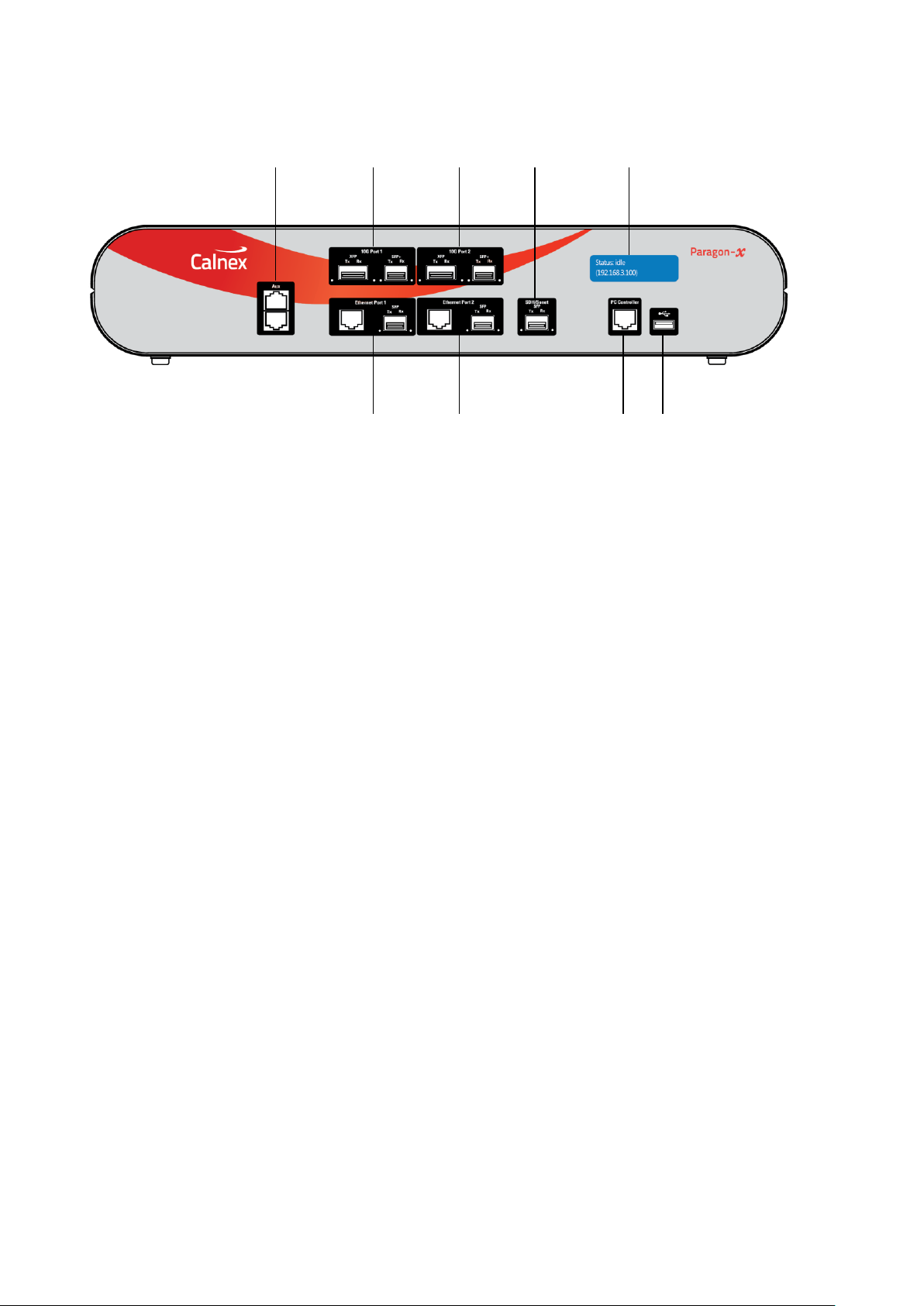
•Front Panel Description
•Rear Panel Description
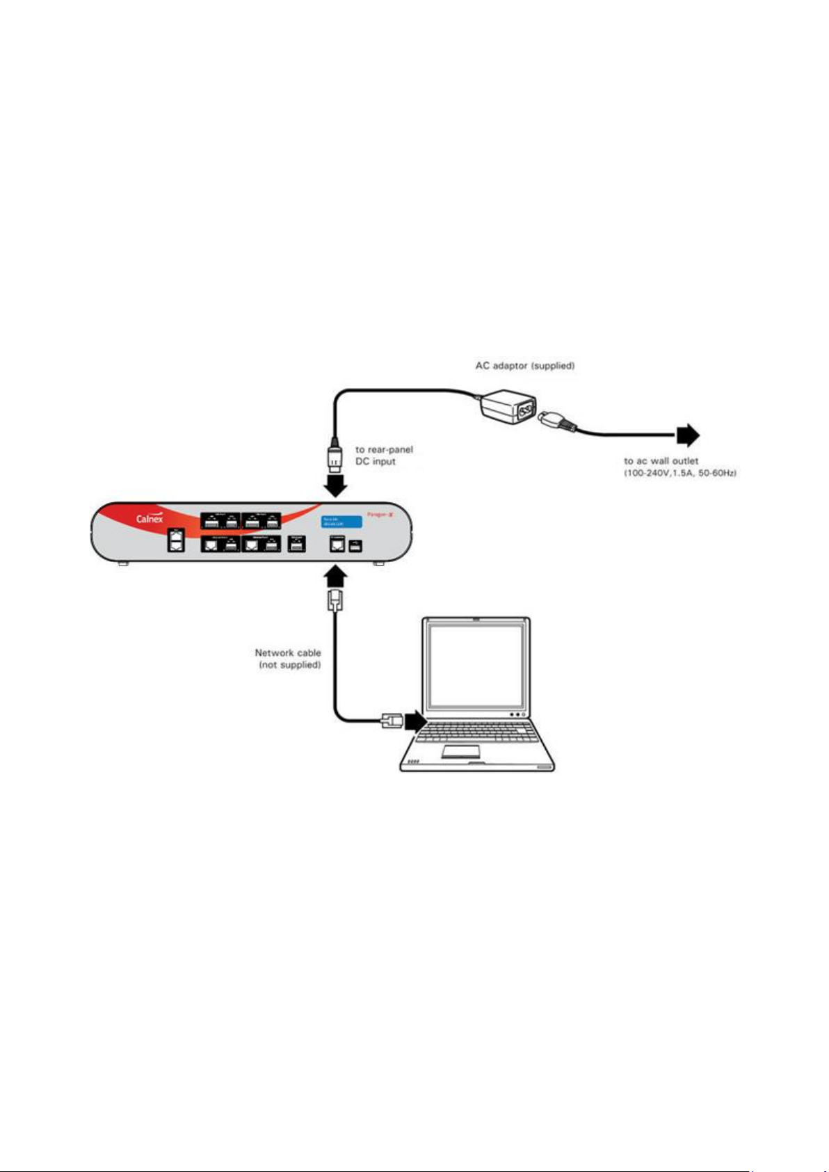
•Connecting Power and Your Computer to Paragon-X
•Configuring Your Computer
•Installing the Application Software
•Graphical User Interface Basics
•Paragon-X Workflow
•Paragon-X Constant Time Error (cTE)
•Rb/GPS External Timing Reference Accessory
•1pps/ToD/Frequency Converter Accessory
Introduction
For Next-Gen technologies up to 10Gb/s, the Calnex Paragon-X offers direct insight into actual device
and service behaviour, and the ability to generate a broad range of real-world disruption scenarios to
validate the operation of your network devices.
Paragon-X functions (with appropriate options installed):
•T1/E1/2MHz wander measurement
•1pps accuracy and wander measurement
•Time of Day display from serial interface to multiple standards
•Ethernet interface rates of 100M, 1G and 10Gb/s
•1588: PDV Measurement
•1588: One-box BC, TC & OC Test including Master/Slave Emulation and Time Error Measurement
•1588: Through-Mode Time Error Measurement
•Sync-E jitter tolerance and generation measurements to G.8262/O.174
•Sync-E wander tolerance, transfer and generation measurement to G.8262/O.174
•External references: frequency and 1pps
•Y.1731 OAM
•MPLS-TP OAM
•CES
•Edit and replay captured PDV
•Through-mode packet delay and corruption
•Compatible external Rb/GPS reference and 1pps/ToD/Frequency converter accessories

Paragon-X Getting Started Guide Page 4of 28
Supplied Accessories
After unpacking the Paragon-X unit, make sure that the accessories below are present. If anything is
missing, contact Calnex Solutions by telephone: +44 (0) 1506 671 416 or by email:
Paragon-X
AC adaptor (1)
Power cord (1)
USB memory stick (1)
Getting Started Guide (1)
Rb/GPS External Reference
AC adaptor (1)
Power cord (1)
GPS antenna (1)
Antenna connecting cables and lightning arrestor (1)
1pps/ToD/Frequency Converter
AC adaptor (1) –note, device may also be powered from PC or other live USB connector

Paragon-X Getting Started Guide Page 5of 28
Front Panel Description
1. Aux ports (RJ45)
2 and 3. 10G Ethernet ports
4. This connector is not used
5. Display
6. In earlier versions this connector is not used and does not supply USB power. In later
versions it supplies USB power to the External 1pps/ToD Frequency Converter accessory.
7. PC Controller (RJ45)
8 and 9. 1GbE and 100M Ethernet ports
1. Auxiliary ports (RJ45)
Top Front Aux Port: Time of Day 1pps input, single-ended signal with adjustable threshold, pin 1
+ve and pin 2 GND. Input impedance 50Ω. Threshold range 0.5V to 2.5V. Use external
1pps/ToD/Frequency converter accessory to convert from high-impedance single-ended signal or RS-
422 balanced signal.
Lower Front Aux Port (earlier versions): 10MHz Clock Out frequency-locked to whatever reference
the Paragon-X is using (internal or external), pin 1 +ve and pin 2 GND. In Master/Slave Emulation
Mode this is User Selectable between the 10MHz Clock Out and a 1PPS Reference Output locked to
whatever Paragon-X 1PPS reference is in use. The 1PPS output signal is only present when the Master
is enabled and generating packets (all cases except Master Test configuration).
The 1PPS output is locked to whatever Paragon-X 1PPS reference is in use, pin 3 +ve and pin 6 GND.
Both outputs use an in-line or series 50Ωresistor and can drive high impedance inputs as well as 50Ω
inputs.
1
2
3
4
5
6
7
8
9

Paragon-X Getting Started Guide Page 6of 28
Lower Front Aux Port (later versions): 10MHz Clock Out frequency-locked to whatever reference
the Paragon-X is using (internal or external), pin 1 +ve and pin 2 GND. In Master/Slave Emulation
Mode there is also a 1PPS Reference Output. The 1PPS output signal is only present when the Master
is enabled and generating packets (all cases except Master Test configuration).
The 1PPS output is locked to whatever Paragon-X 1PPS reference is in use, pin 3 +ve and pin 6 GND.
Both outputs use an in-line or series 50Ωresistor and can drive high impedance inputs as well as 50Ω
inputs.
2 and 3. 10G Ethernet ports
This is for connections to 10G interfaces on Ethernet devices. There are two types of pluggable
interface supported, SFP+ and XFP (both, customer supplied). Only SFP+ interface is supported for
Sync-E jitter measurements.

Paragon-X Getting Started Guide Page 7of 28
5. Display
During the power up process, the display will show the Calnex logo then information regarding the IP
address and port number Paragon-X is configured to use. After approx. 90s the unit will be available
for operation.
6. USB port
Not used.
7. PC Controller RJ45
This is a 100Mb Ethernet port used for directly connecting Paragon-X to a PC or laptop running
Microsoft Windows 7 or Windows 10 OS (the ‘host PC’).
Connection over a network is possible but not recommended; see Calnex Application Note CX5006 on
Paragon PC specification and management for more details.
8 and 9. 1GbE and 100M Ethernet ports
For connection to an Ethernet device to be tested. The left port in each block 8 and 9 is a 100M or
1GbE RJ45 electrical port; the right side is a 100M or 1GbE optical port. Optical ports require the use
of SGMII-type SFPs (not supplied).

Paragon-X Getting Started Guide Page 8of 28
Rear Panel Description
Earlier Versions
Later Versions
10. DC Power Input
11. Power Switch
12. 1PPS Reference Input
13. Wander Measurement Inputs
14. Reference Inputs
15. Reset Switch
16. 64K AMI Reference Input
17. GPS Reference
18. GPS Antenna Input
10. DC Power Input
For connection to supplied AC power adaptor only.
Power supply: AC input 100 - 240V, 1.5A, 50 - 60Hz.
11. Power Switch

Paragon-X Getting Started Guide Page 9of 28
Switches mains input to Paragon-X on or off.
12. 1PPS Reference Input
Typically, sourced from an external GPS receiver (e.g. Paragon-X option 132). Alternative to 1PPS
input on connector 17. Single-ended 75ΩBNC connector.
13. Wander Measurement Inputs
Accept T1, E1 (75Ωunbalanced or 100Ωbalanced) and 2.048MHz inputs. In external wander
generation mode, accepts T1, E1, 2.048MHz and 10MHz wander-modulated signals from an external
source.
Input signal amplitude range: 1V–3V peak to peak into 50Ω.
14. Reference Inputs
For connection to T1, E1, 2.048MHz or 10MHz clock reference signals.
Clock input amplitude range: 0.6V-3V peak to peak.
See also connectors 16 and 17 below.
15. Reset Switch
Resets Paragon-X to its power-on condition and resets IP address to factory default 192.168.3.100
16. 64K AMI Reference Input
For connection to 64kb/s external system reference clock.
Pin 2 = tip (+), pin 6 = ring (-), pin 1 = GND.
17. GPS Reference
An alternative to connector 12, accepts a 1PPS reference input signal on pin 9 (pin 5 GND).
Accepts Time of Day (ToD) message input as RS-232 on pin 2 (pin 5 GND) and can generate ToD
message output as RS-232 on pin 3 (pin 5 GND). Paragon-X can display ToD messages directly as
received, or qualified by 1PPS signal.
18. GPS Antenna Input
Not used.
Labels and Disposal Information
The Waste Electrical and Electronic Equipment regulations label indicates that the
equipment should only be disposed of through an approved method. At the end of life
please dispose of the equipment through a recognized and approved scheme fulfilling the
local environmental requirements. Alternatively contact Calnex Solutions Ltd to have them
arrange for return and disposal.
The CE mark indicates that the product meets all the appropriate provisions of the relevant
legislation contained in the European Directives.

Paragon-X Getting Started Guide Page 10 of 28
Connecting Power and Your Computer to Paragon-X
1. Connect your computer to the PC Controller port on the front panel of Paragon-X.
2. Connect the AC adaptor to the rear panel DC power input connector.
3. Connect the power cord to the AC adaptor and plug into an AC outlet.
4. Use Paragon-X’s rear panel power switch, marked I/0, to switch on Paragon-X.
5. The blue display on the front panel will turn on. Paragon-X is initialised and ready to use after
approximately 90 seconds. Note that on first power up, the IP address shown on the display is
factory-preset and can be changed to meet your network requirement. To do this, install the
Paragon-X application software (as described in ‘Installing the Application Software’), then click on
Instrument(s) then Change IP Settings.

Paragon-X Getting Started Guide Page 11 of 28
Configuring Your Computer
Depending on which version of Microsoft Windows OS is running on the host computer (Windows 7 or
Windows 10), you must modify the computer network settings as described in the following sections.
For further information on the minimum required specifications for your computer and notes on
optimising performance, refer to the Calnex Application Note ‘Paragon PC Specification and
Management’from the Resources section of www.calnexsol.com (registration required).
Note that the instructions below refer to a direct connection to Paragon-X: the recommended
configuration deploys a host PC running the Paragon-X application connected directly to the Paragon-
X. The host PC has two Ethernet ports to allow connection directly to the Paragon-X and to the network.
Control of Paragon-X is then enabled by a remote desktop connection to the host PC from any
accessible PC.
When connecting to the network, be aware of the IP address range used in that network and any
associated subnet mask and default gateway addressing requirements. If in doubt, contact your
System Administrator for the appropriate information.
While it is possible to connect to Paragon-X over a network, performance in this situation is not
guaranteed and so this should be avoided if possible
Microsoft Windows 7
1. Click on Start > Control Panel > Network and Internet > Network and Sharing Center
then Change Adapter Settings.
2. Right-click Local Area Connection > Properties.
3. Click on Internet Protocol Version 4 (TCP/IPv4) > Properties.
4. Click on Use the following IP address and enter an IP address, Subnet mask and Default
gateway. The IP address used should be different from the Paragon-X IP address (shown on
its display) only in the last 3 digits e.g. for a Paragon-X IP address of 192.168.3.100 a suitable
host PC IP address would be 192.168.3.105. This ensures Paragon-X will have an IP address
on the same subnet as the host PC.
Windows Firewall settings may need modified to allow connection to Paragon-X as this communication
requires access to the following ports. If issues are found trying when to connect to Paragon-X or run
the associated software, first confirm that these ports are available:
Paragon-X remote client application: ports 9990 and 9000
CAT and PFV: ports 1337 and 1338
If Paragon-X is connected via a LAN you may need to contact your local system administrator. For
direct connections, it may be possible to disable Windows Firewall, but before doing so relevant local
IT security policies and controls should be confirmed.
Microsoft Windows 10
1. Open the Windows Start Menu, then type Connections in the search box and select the View
Network Connections item from the resulting list in the Settings subsection.
2. In the window which will now be displayed, right-click on the Local Area Connection icon for the
adapter to which Paragon-X is connected and click the Properties item (this may require
Administrator credentials to be supplied, depending on the user type configured).
3. Click on Internet Protocol Version 4 (TCP/IPv4) then the Properties button.
4. Click on Use the following IP address and enter an IP address, Subnet mask and Default
gateway. The IP address used should be different from the Paragon-X IP address (shown on its
display) only in the last 3 digits e.g. for a Paragon-X IP address of 192.168.3.100 a suitable host
PC IP address would be 192.168.3.105. This ensures Paragon-X will have an IP address on the
same subnet as the host PC.

Paragon-X Getting Started Guide Page 12 of 28
Windows Firewall settings may need modified to allow connection to Paragon-X as this communication
requires access to the following ports. If issues are found trying when to connect to Paragon-X or run
the associated software, first confirm that these ports are available:
Paragon-X remote client application: ports 9990 and 9000
CAT and PFV: ports 1337 and 1338
If Paragon-X is connected via a LAN you may need to contact the local system administrator. For direct
connections, it may be possible to disable Windows Firewall, but before doing so relevant local IT
security policies and controls should be confirmed.

Paragon-X Getting Started Guide Page 13 of 28
Installing the Application Software
The Paragon-X software comprises two parts: embedded software which is pre-installed on the
Paragon-X hardware prior to delivery, and application software supplied on a USB memory stick (or
by download from www.calnexsol.com) which requires installing on the host PC to allow control of
Paragon-X. To install this application software:
1. Insert the USB stick into a USB port on the host PC. Depending on the PC configuration, Windows
Explorer may launch automatically. If it does not, open Windows Explorer. Browse to the USB
device, double click the setup.exe file then follow the on-screen instructions. A number of
applications will be installed in sequence.
2. Once the installation process is complete, click on Start > All Programs > Calnex > Paragon-
Xto launch the Paragon-X Remote Client app as shown below (note that the path may be different
if the settings were changed from default during the installation process):
The software version of the Paragon-X application can be found by clicking on Help > About
Paragon Remote Client.
The latest release software is available from https://calnexsol.com/en/resources-en/product-
software (registration required). For information on how to upgrade your current capability or add
3. For full functionality, Wireshark should also be installed on the host PC. A version may be included
on the installation USB stick provided with Paragon-X, or the latest version may be downloaded
from www.wireshark.org. Once obtained, double click on the Wireshark***.exe file and follow the
onscreen prompts.
4. It is possible to use the Paragon-X Remote Client app without being connected to an instrument.
This allows existing capture and replay files to be manipulated without requiring access to the
Paragon-X hardware, or, by clicking Help then Demo, a demo mode which uses pre-configured
demo capture files to simulate measurements may be accessed.

Paragon-X Getting Started Guide Page 14 of 28
Graphical User Interface Basics
1. WORKFLOW
Use these buttons in top-to-bottom sequence to configure Paragon-X, capture data and apply
impairments as required. Further information on each is available below.
2. SETTINGS
Shows current Paragon-X interface settings.
3. STATUS
For each item below, the colour indicates the status:
green - no alarms
red - current alarm
yellow - historic alarm (i.e. alarm has occurred within the current test duration)
grey - not active in the current configuration
•Link: indicates if there is a physical Ethernet connection to Paragon-X by detecting transitions on
the selected port Rx side.
•Good Pkts: indicates Paragon-X is receiving Ethernet packets with no PCS or checksum errors.
Legend changes to BAD PACKETS and red indicator if condition fails.
•Ref: indicates if Paragon-X is locked to the selected frequency reference source as configured in
the Setup Interface window.
1
3
2
4
5
6
8
7

Paragon-X Getting Started Guide Page 15 of 28
•SyncE: active when Sync-E Clock Rx >Tx selected in the Setup Interface window. Indicates
Paragon-X Tx clock is locked to the incoming Sync-E line signal.
•Wander: indicates Paragon-X is locked to the selected wander measurement input signal (see
‘Wander Measurement Input’rear panel connector description).
•1PPS Ref: indicates Paragon-X is locked to the 1PPS reference (see ‘1PPS and 64K AMI’panel
connector descriptions).
•1PPS Meas: indicates Paragon-X is receiving a 1PPS measurement input (see ‘Aux ports RJ45’
front panel connector description).
•Jitter: indicates Paragon-X is locked to the selected jitter measurement input signal.
4. Icon Menu Bar
Provides quick access to various Paragon-X functions.
5. Main Menu
Enables access to dropdown menus for configuration, settings and measurement modes of the
Paragon-X. Many provide access to functions also available via workflow buttons and icon menu bar
items, allowing alternative methods for controlling Paragon-X depending on user preference.
6. Mode Title Bar
Identifies the type of decoded information displayed; column names are dependent on the type of data
shown. Alarms, errors and sequence anomalies in captured data (live or pre-captured) are highlighted
by a red exclamation mark.
7. Tabulated Captured Data
Displays decoded information from the data captured by Paragon-X, either live or loaded from a saved
capture file. Actual display depends on the type of data being decoded, but may include message and
timing information.
8. Flow Filter
Indicates whether any active filters have been set for capturing or replaying packets. Values displayed
are xxx for no filter and SET if a filter is configured. Filters can be viewed and set manually using the
Set button, or set automatically using Flow Wizard accessed via the Select Flow button. Active
filters may be cleared by clicking the Clear button in this section.

Paragon-X Getting Started Guide Page 16 of 28
Paragon-X Workflow
From the Workflow buttons:
1. The first step is to connect to Paragon-X. Click on Start Up then Connect.
2. Enter the Paragon-X IP address and your username, if required (the default is your PC username)
then click on OK. If failure to connect occurs, check your network connection and host PC network
adapter settings (see details in previous section).
3. Click on Operating Mode.
4. Select the traffic type.
Note: available modes will depend on the options fitted (licenced) on Paragon-X:
CES: Circuit Emulation Service, for example, CESoP, SAToP, TDMoIP. (Requires Option 202)
1588v2: IEEE1588v2 advanced analysis features
Enable Master/Slave Emulation. (Requires Option 250 or 252)
Services: Analyse and impair any Ethernet or IP traffic (available on all instruments).
Sync-E: Synchronous Ethernet (Requires Option 213)
NTP: NTP Capture, Header decode & Timing Analysis (Requires Option 404)
Ethernet OAM: OAM capture, overwrite and impairment generation to 802.1ag and Y.1731
(Requires Option 301)
MPLS-TP OAM: MPLS Transport Profile OAM (PTN version using Y.1731) capture, overwrite and
impairment generation (Requires Option 302)

Paragon-X Getting Started Guide Page 17 of 28
5. Click on Measurements. Select the required measurements from the displayed list (available
options are dependent on the configuration and traffic type selected). An example selection is
shown below:
6. Click on Close to close the dialog box.
7. The Configure Capture workflow button may then be used to configure detailed settings for
the selected measurements.
8. Click on Setup Interface to configure the ethernet interfaces, references and measurement
parameters to match the requirements of the device to be tested and inputs available to
Paragon-X. Note: suitable SFP/SFP+ or XFPs must be inserted into the relevant Paragon-X ports
to allow the selection of the associated optical interface:

Paragon-X Getting Started Guide Page 18 of 28
9. Click on Close to close the dialog box.
10. To manually set filters, click on Select Flow. Note: this step is not required for testing using
1588 Master/Slave Emulation, and that this button becomes Set Flow Filter when the operating
mode is Ethernet OAM.
11. Click on Capture Packets then Stop Capture.
12. Click on Flow Wizard to display all captured flows, then select those of interest by clicking on
each. Multiple lines may be selected by ctrl-clicking. Set Impair to set the filters for packet
impairments, and Set Capture for packet decode and measurement filter setting. Note: the Set
impair option is only available in Master-Slave Emulation mode when capturing on the Paragon-
X Master port, or in Thru mode.
13. Click on the window control X in the top-right corner to close the dialog box.
14. For CES, 1588v2, Service and Sync-E operating modes, click on Configure Capture. Note that
this button becomes All Packet Capture and Analysis in Ethernet OAM operating mode.
Please refer to appropriate Calnex application notes and SUS release notes for detailed operational
steps and result interpretation in relation to specific tests. These may be accessed from the Help menu
in the Paragon-X application.

Paragon-X Getting Started Guide Page 19 of 28
Paragon-X Constant Time Error (cTE) measurement
This section details how to perform a Time Error test. This requires Paragon-X to have Opt. 250
(Master/Slave Emulation End to End) or Opt. 252 (Master/Slave Emulation Peer to Peer) fitted.
1. In Operating Mode, select 1588v2 and tick the Enable Master/Slave Emulation box.
2. On the Setup Interface screen, configure the ethernet interface to match the device under test
e.g. 1GbE optical*.
3. Click the Master/Slave Emulation button on the main GUI then configure for the device under
test e.g. select Boundary Clock in the Test Configuration dropdown menu. Select a suitable
profile from the dropdown menu above the test set-up graphic, or use the Configure button to
access manual settings. Note that the displayed image will change depending on which type of
test has been selected and so provides a convenient checkpoint for device connectivity
requirement.
4. Press the Start button in the Measurement section. This will start master-slave emulation, set up
the appropriate capture filters, and start a capture.
Note: when configured to use 100M line rate, instead of using the Start button, first enable the
required PTP filters by using Capture > Flow Filter menu option then start MSE by using the
green Master+Slave button before starting capture. This allows Paragon-X to adjust for clock-
cycle offsets inherent at this rate.
5. Allow to run for 30s (or longer if desired).
6. Stop the capture by clicking the red Stop Capture button, then stop master-slave emulation by
clicking the red Master+Slave button at the bottom of the master-slave screen.

Paragon-X Getting Started Guide Page 20 of 28
7. Select Time Error Measurement from the Tools >Calnex Analysis Tool (1588v2) menu.
This will start CAT, which allows the observation and analysis of data captured by the Paragon-X
hardware and application.
8. When CAT launches, the Select file page is initially displayed and the live capture file pre-selected.
The Select Metrics button presents a list of available clock, packet and time error metrics, with
those appropriate for the current test pre-enabled. for further information on any given metric,
including their meaning, any relevant Standards, and the maths used in their calculation, select
the ‘?’ icon beside its entry.
9. The View Results button will display graphs and statistics for the currently-loaded data. Each type
of metric is presented in its own tab, and may be viewed by clicking on each as appropriate.
*Please note that it is expected that idle symbols are transmitted in pairs. If testing using 100M interfaces,
please confirm with the PHY vendor that their implementation uses this technique. At 100M rate, the presence
of odd idle symbols will result in timing measurements being offset by one clock cycle (40ns).
Table of contents
Other Calnex Test Equipment manuals
Popular Test Equipment manuals by other brands

Bona Caeli
Bona Caeli SENSEMini instruction manual

Fluke
Fluke 718 1G Product overview

ULTIMATE SPEED
ULTIMATE SPEED UAWSB 2 A1 operating instructions

Agilent Technologies
Agilent Technologies InfiniiVision 5000 Series user guide

Hanna Instruments
Hanna Instruments HI 95706C instruction manual

sauter
sauter TVL-XL installation manual