8
MiniFlex
®
Flexible AC Current Probe
CHAPTER 3
SPECIFICATIONS
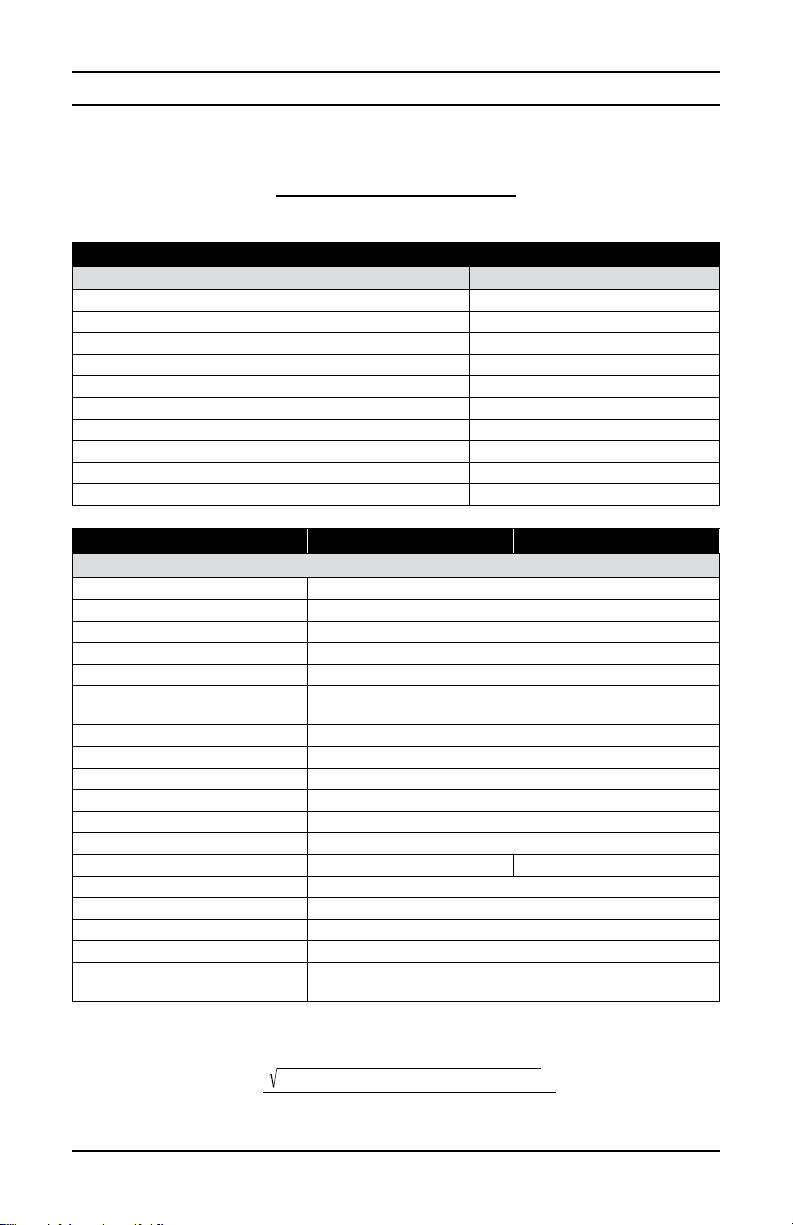
REFERENCE CONDITIONS
Quantity of influence Reference values
Temperature 23 ± 5° C
Relative humidity 20 to 75% RH
Frequency of the signal measured 40 to 400Hz
Type of signal Sinusoidal
External electric field < 1V/m
External DC magnetic field (earth field) < 40A/m
External AC magnetic field None
Position of the conductor Centered in the measurement coil
Shape of the measurement coil Nearly circular
Input impedance of the display device connected to housing ≥1MW
MODEL MF 300-6-2-10-HF MF 300-10-2-10-HF
ELECTRICAL
Range 30/300A
Signal Output 100mV/10mV/A
Frequency Range 5Hz to 1MHz @ -3db
Frequency Limitation none
Influence Of Conductor Positioning 1.5% typical, 3% max
Influence Of Conductor Positioning
In Sensor Against Handle 4% typical, 6% max
External Conductor Influence 35dB to 40dB on contact
Accuracy ± 1% +0.3A
Common Mode Rejection 100dB typical, 80dB min
Max peak factor (1) at I nominal 1.5
Residual noise at I = 0 (Arms) (2) 0.3A
Max phase shift at 1kHz (°) 1
Max offset voltage (mVDC)50 5
Max output voltage (Vpeak) ± 4.5
Output impedance (kW)1
Power Source 9V alkaline battery (6LF22)
Battery Life 140 hrs continuous operation or 10,000 one minute measurements
Battery Indicator When Green LED starts blinking, remaining life is approx 8 hours;
When LED is OFF, the battery needs to be replaced
(1):PeakfactorPF=Vpeak/Vrms
(2):Theresidualnoiseaffectsthemeasurementuncertaintyaccordingtotheformula:
(I measured x 0.01)2+ (residual noise)2
global uncertainty = (I measured ≠ 0)
Ifthecurrentmeasurediszero,theuncertaintyisequaltotheresidualnoise.