Hydrajaws 2008 User manual

Operating Instructions
HYD R A J AW S
LIMITED
2008 Model Tester

Hole 26mm
diameter
3
Model 2008 Tester Parts
1. Operating Nut
2. Digital Gauge
3. Load Spreading Bridge
4. M20 Connecting Rod
5. M20 Adjustable Nut
6. 22mm Ratchet Spanner
7. Threaded Adaptors M12-M30
8. Spirit Level
Model 2008 Bridge Footprint
2
SAFETY RULES
• Modication of the tester, or tampering
with it’s parts is not permissible.
• Observe the information printed in the
operating instructions applicable to
operation care and maintenance.
• The tester and its accessories may
present hazards when used incorrectly
by untrained personnel or not as
directed.
• Use only the genuine Hydrajaws
accessories or ancillary equipment
listed in the operating instructions.
The Hydrajaws model 2008
Heavy Duty Tester is designed
for establishing linear loading of
mechanical and resin anchors, eye
type anchors, threaded bar, re-bar
and structural bolts and xings to a
maximum load of 145kN.
USE OF THE TESTER AS DIRECTED
The tester is intended for use by skilled
personnel with the appropriate training
and knowledge of the applicable
safety precautions.
GENERAL DESCRIPTION
It is essential that the
operating instructions
are read before the tester is
operated for the rst time.
Always keep these operating
instructions together with
the tester.
Ensure that the operating
instructions are with the
tester when it is given to
other persons.
TECHNICAL SPECIFICATIONS
Intelligent digital pressure gauge
• 0-145kN (4 segment LCD display)
• Accurate to +/-2.5% FSD
• Indication of pull-out load
• Rise and fall output
• Maximum load achieved function
• Calibration in kN
• Traceable Calibration Certicate
supplied valid for 1 year
• Material: stainless steel and ceramic
• Battery Powered (PP3)
2008 Model Tester
1
7
8
3
6
2
4
5
48mm
48mm
26mm
30mm Thick
Aluminium
30mm Thick
Aluminium
M20
M20
M20
M20 M20
M20
Legs
*
*
*15MO
*Mounting
Holes
*Mounting
Holes
Datum
x 2 proles for dierent
edge distance
x 2 proles for dierent
edge distance
* Mounting
Holes
Feet Outer
Edge
x 2 proles for
dierent
edge distance
62mm
62mm
75m
141mm
216mm
265mm
216mm 230mm
265mm 290mm
15MO
173mm
173mm
188mm
35mm
Dia
40mm Dia
CONTENTS
Page
2008 Model Tester Parts 2
General description 3
Technical Specications 3
Kit contents 4
1. LOAD SPREADING
BRIDGE - set up 5
2. General Testing
Procedure - set up 6
3. General Testing
Procedure - Operating the tester 7
4. Eyebolt Testing 8
5. Re-bar operating instructions 9
6. 2008 MODEL TESTER ASSEMBLY
TO 12.5 TON LOAD SPREADING
BRIDGE 11
6. GENERAL GUIDELINES
FOR TESTING 11
7. Operating the digital gauge 12
8. Operating instructions for
optional Bluetooth Digital Gauge 13
9. Changing the gauge battery 14
10. Calibration/Repair/
Replacement of gauge 14
11. Bluetooth Digital Option -
Cable removal 15

4 5
1. Model 2008 Tester Body
2. 22mm Operating Nut
3. 0-145kN Digital Gauge
(Bluetooth version optional for recording
data via suitable mobile device)
4. Offset Load Spreading Bridge plate with
10mm eye hook
5. 3 Telescopic legs with fully adjustable
swivel feet
6. M20 Connecting Rod 400mm
7. M20 Adjustable Nut
8. M24 Ratchet Spanner
9. 5 Threaded Adaptors
M20 > M12, M16, M20, M24, M30
10. Spirit level
11. Allen Keys
12. Spare screws
13. Carry Case with Foam Filler
14. Operating Instructions
15. Calibration Certicate
KIT CONTENTS
1
2
12
11
8
5
5
5
6
7
9
13
3
4
10
1. LOAD SPREADING BRIDGE - set up
Operating Instructions
HYDR A J A W S
LIMITED
2008 Model Tester
14
Fig 1
Fig 2
Fig 4Fig 3
15
The bridge has been designed specically
for the model 2008 tester and directs
reaction loads away from the xing (g 1).
The lightweight aluminium load spreading
bridge ts in the carry case disassembled
(g 2). The bridge is simple to assemble
and adjust. Three fully adjustable telescopic
legs offer 11 height positions 25mm apart
(g 3). The legs are held in place with
steel ball pins.
The swivel feet offer 30mm of ne
adjustment.
The triangular shape bridge plate is
deliberately offset to offer two different
close to edge testing distances in
relationship to the xing under test.
The tester can be secured to the bridge
plate in two positions with the supplied
cap screws (g 4). Securing the tester
to the plate is not crucial when the tester
is being operated in a horizontal position
however is essential when the tester is in
a vertical position or inverted.

76
Assemble the load spreading bridge.
Secure the tester to the bridge if
appropriate.
Position the tester and bridge over
the xing and using the M20 connecting
rod pass this through the tester and
bridge (g 5).
Switch the digital gauge on (see separate
gauge operating instructions in this
manual).
Commence applying the load to the xing
by turning the hexagon nut on the end
of the operating piston in a clockwise
direction by hand until tight or reading
appears on gauge.
Apply load using the ratchet spanner (g
10) and observe the reading on the gauge
until the required test load is reached. This
reading could decay due to rst movement
or creep on the anchor. Continue to apply
the load to the required reading and
observe that the loading remains steady.
Should a serious drop in the indicated
load occur again, the xing is likely to be
insecure and should be investigated.
As the digital gauge is very accurate a
drop off will be noticeable but this should
stabilise after a period of time. If the
reading continues to drop off, further
investigation of the xing would be
required.
To release the load, reverse the ratchet
ring spanner and turn the hexagon nut
anticlockwise and observe the load
reading on the gauge until it approaches
zero. Unwind the operating nut by hand
until it is resting on the stop and unwind
the adjustable nut and remove.
DO NOT CONTINUE TO UNWIND
AGAINST THE STOP, OTHERWISE
SERIOUS DAMAGE WILL OCCUR.
Fig 5
Fig 6
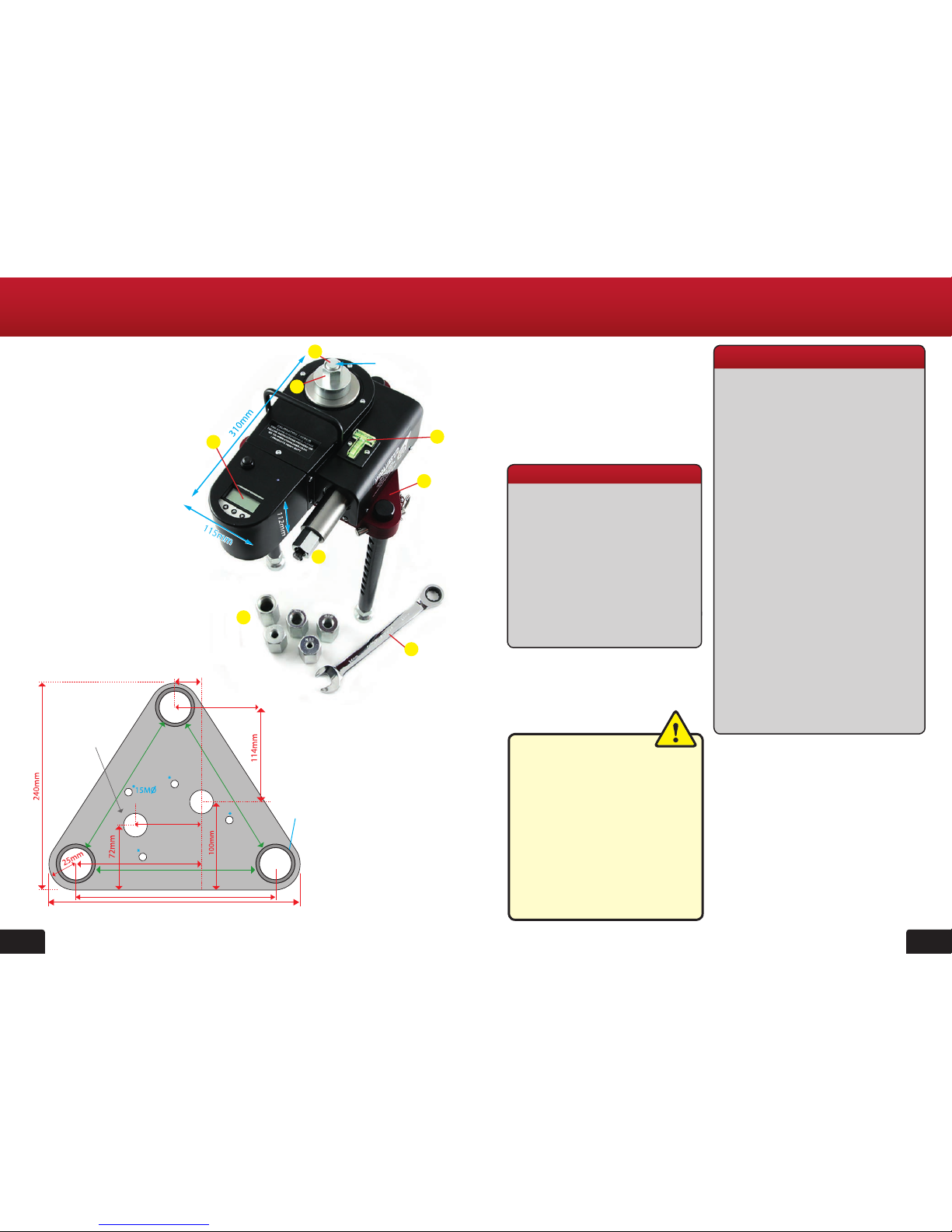
2. General Testing Procedure - set up 3. General Testing Procedure - Operating the tester
M20
connecting
rod
Threaded
adaptor
WARNING
DO NOT unwind the
piston past the stop!
If after a test, the operating nut has
been unwound fully however the top
piston remains tight, untighten the
adjustable nut with the ratchet spanner.
Connect the M20 connecting rod to xing
using the appropriate threaded adaptor
(g 6).
The standard tester kit features ve metric
threaded adaptors:
M20>M12, M20>M16, M20>M20,
M20>M24 or M20>M30.
Note: Other metric thread sizes are
available via special order.
Imperial UNC adaptors are available
from stock.
Sizes; 3/8”, ½”, 5/8”, 3/4”& 1”
Install M20 adjusting nut (g 7) on top of
the threaded pull rod.
Adjust the 3 telescopic legs to an
appropriate height, take up any initial
slack using the threaded pull rod so
that the xing under test remains
connected with no movement between
the connecting rod nut and the top of the
tester.
Ensure the tester is level by adjusting the
swivel feet against the level bubble on the
top of the tester body (g 8).
Each threaded swivel foot features 30mm
of ne adjustment.
Tighten with ratchet spanner (g 9).
Fig 8
Fig 10
Fig 7
Fig 9

98
5. Re-bar operating instructions
1. The Model 2008 Portable Heavy Duty
Tester will accept Rebar adaptors 6mm,
8mm, 10mm, 12mm, 14mm, 16mm,
18mm, 20mm & 22mm re-bar directly
through the cylinder.
2. Place the tester and triangular load
spreading bridge directly over the re-bar
by passing through the cylinder hole.
3. Place the tapered barrel over the re-bar
with the smaller diameter to the bottom
until it rests on top of the cylinder. Insert
the collet (3pcs) into the barrel and this
will sit ush or just inside (g 11) .
5. Adjust the ne thread at the base of
each foot and on the triangular load
spreading bridge legs by turning each
foot clockwise until all the slack is taken
up and the collet has gripped onto the
re-bar. Failure to do this procedure may
result in the tester running out of stroke.
(10mm) (g 12).
6. Ensure the tester is level by observing
the spirit level on top of the tester case
(g 13).
4. Eyebolt testing
1. Screw the M20 connecting rod into
the heavy duty clevis and ensure the
thread engages fully so is ush with the
block.
2. Adjust the 3 telescopic legs on the
bridge so that the pin lines up with the
eye under test. Place the pin through
the eye and secure the clevis and pin.
3. Take up any further slack by either
adjusting the thread on the feet and/or
tightening the M20 adjustable nut.
4. Apply the load by operating the ratchet
spanner clockwise observing the
reading on the gauge.
5. After the test release the load by
operating the ratchet spanner anti-
clockwise and remove the clevis
and pin.
30mm
49mm
44mm
140mm
M20
SIDE VIEW
100mm
100mm
30mm
FRONT VIEW
Heavy duty clevis sizes
Fig 11
Fig 13Fig 12

1110
6. 2008 MODEL TESTER ASSEMBLY TO
12.5 TON LOAD SPREADING BRIDGE
1. Screw the three M24 legs into the
bridge to the desired height and adjust
to a level position. (Lock the x3 M24
nuts to the underside of the bridge).
2. Remove the silver locating plate from
the top of the bridge using the 5mm
allen key and remove the 2 M8 x 15
counter sunk screws.
3. Secure the plate to the Model 2008
tester using holes marked A with the x
2 M8 x 25 counter sunk screws and this
will allow the tester to be parallel when
mounted on the bridge.
4. Holes marked B will allow the tester
to be at 90 degrees to the bridge if
required.
5. Secure the plate to the load spreading
bridge with the x 2 M8 x 15 counter
sunk screws (g 17).
6. Spare screws are also provided for the
tester assembly and bridge assembly.
7. Operate the tester by using the M24
ratchet spanner to the desired load
(g 14).
8. Once the test is complete, release
the load fully and lower the threaded
feet on each leg by turning the legs
anti clockwise. Full adjustment needs
to be made so that the barrel can be
removed from the collet.
9. Hit the top edges of the barrel with a
hammer downwards until the collet
can be removed, further adjustment to
lower the bridge legs may be required.
(g 15).
5. Re-bar operating instructions continued..
Fig 14
Fig 16
Fig 17
Fig 15
PLEASE NOTE THAT THE MAXIMUM CAPACITY OF
THIS LOAD SPREADING BRIDGE IS 12.5 TON (125kN).
This load should not be exceeded.

1312
7. Operating the digital gauge
The maximum load capacity of the MAN-SD1S-C transducer at the base of the gauge is
0–145kN and the gauge should not be loaded above this gure as permanent damage will
occur. Eventually the battery will require replacement (when warning indicator comes on)
and the battery tted under the removable cover on the back of the gauge. Replace with
type PP3 9 volt unit.
Operate Gauge in ‘Normal rise and fall’ mode
Press button to switch gauge on to ‘Normal rise and fall mode’.
This will give a load reading in kN rising as the operating handle on the
tester is turned clockwise. By turning the handle anti-clockwise the load
will decrease and show the reading decreasing.
Press to switch off gauge when nished.
Operate Gauge in ‘Peak Hold’ mode
1. Press button to switch gauge on
2. Press then . On display ‘OFF’ will appear.
3. Press twice to display MAX.
4. Press to display PASS.
5. Press and together for about 3 seconds then release.
A small vertical arrow will appear in left hand side of screen.
6. To zero reading press and wait 2 seconds.
Gauge is now in peak hold mode and will display the maximum
load achieved and retain this even when the load has decreased.
Return to ‘Normal rise and fall’ mode
1. Press then and display shows MAX.
2. Press and display reads OFF.
3. Press twice and display reads 0.
4. Press and together twice until display reads - 0.0
(The last digit may not read 0 due to ambient temperature.)
Press to switch off gauge.
To Zero the gauge
If the gauge is reading a small
amount (0.32 for example) when
no load is applied - use the
following instructions to re-set the
display to zero.
First release any pressure held in
the Hydraulic Coupler by pushing
in the pin at the base of the
coupler.
Press to turn on then , display=’Pdu’
Press display = ‘OFF’
Press display = ‘PASS’
Press display = ‘0’
Press until reading reaches ‘5’
Press display = ‘ZERO’
Press display = ‘SET’
Press display = ‘PSET’
Press display = ‘5’
Press display = ‘0.0’
8. Operating instructions for optional Bluetooth
Digital Gauge
Hydrajaws revolutionary digital technology
captures test results using an Android OS
mobile device and dedicated software ap-
plication, allowing for instant visual graphs
onsite for anchors & eyebolts. The digital
system using Bluetooth produces real time
visual graphs for each test.
A button and active LED on the top of
the Model 2008 tester housing indicates
that the tester is equipped with this feature
(g 18).
To switch on the Bluetooth element simply
press the button and the LED light will
eliminate and begin to esh. Open the
software application on the mobile device
and select the tester gauge to establish a
connection. When a Bluetooth connection
has been established the LED will become
constant.
Turn on the digital gauge as normal
via the P button and operate as normal.
Loadings will be visible on the tester
gauge and results will be recorded on the
mobile device*.
HYD R A J AW S
DIGITAL
The Bluetooth digital gauge can be retro
tted to a Model 2008 tester.
Fig 18
*Separate
instructions for
use of the Hydrajaws
Bluetooth Digital
will be provided.
CAUTION:
DO NOT ZERO THE GAUGE
WHEN IT IS UNDER LOAD.

9. Changing the gauge battery
1514
The gauge on this unit can be removed for calibration, repair or replacement, please follow
the Instructions below:
1. Remove the front cover piece from the main case by removing the x5 M4 dome
head screws with the allen key provided. Once undone the case will simply lift off
(g 20, 21 & 22).
2. To remove the gauge, reach inside the case and disengage the gauge from
the hydraulic coupling by pulling the coupler connector back (g 23 & 24).
3. Unplug the battery by removing the battery connector (g 25).
4. To install the gauge, push the coupler connector back before pushing the gauge home
into position (g 26).
5. To re-assemble reverse procedure.
If Hydrajaws Bluetooth Digital is tted (A
button and active LED on the top of the
Model 2008 tester housing indicates that the
tester is equipped with this feature) then an
extra cable needs to be disconnected.
1. Follow procedure for removing dust cover,
gauge and battery.
2. The data cable can be disconnected by
pulling rmly (g 27).
10. Calibration / Repair / Replacement of gauge
11 Bluetooth Digital Option - Cable removal
The battery (PP3) is changed by removing
the battery cover (2 x M3 at head screws)
in base of tester. Undo battery strap and
remove battery by disconnecting. Replace
battery and reassemble connections, do not
over-tighten battery strap and replace cover
(g 19).
Fig 19
Fig 20
Fig 23
Fig 22
Fig 25 Fig 26
Fig 21
Fig 27
Fig 24
Data cable

20/21 The Courtyard
Gorsey Lane
Coleshill
Birmingham
B46 1JA, UK.
Tel: +44 (0)1675 430 370
Fax: +44 (0)1675 465 950
email: [email protected]
www.hydrajaws.co.uk
HYD R A J AW S
LIMITED
FOR MORE INFORMATION
ON HYDRAJAWS AND A
FULL RANGE OF TESTING
APPLICATIONS PLEASE VISIT
THE WEBSITE AT:
WWW.HYDRAJAWS.CO.UK
Other manuals for 2008
1
Table of contents
Other Hydrajaws Test Equipment manuals