SCHUNK SST User instructions

Original operating manual
Assembly and operating manual
SST
Sensor tester

Imprint
2
04.00 | SST | Assembly and operating manual | en | 389581
Imprint
Copyright:
This manual is protected by copyright. The author is SCHUNK GmbH & Co. KG. All rights
reserved. Any reproduction, processing, distribution (making available to third parties),
translation or other usage - even excerpts - of the manual is especially prohibited and
requires our written approval.
Technical changes:
We reserve the right to make alterations for the purpose of technical improvement.
Document number: 389581
Version: 04.00|05/06/2019|en
© SCHUNK GmbH & Co. KG
All rights reserved.
Dear Customer,
thank you for trusting our products and our family-owned company, the leading
technology supplier of robots and production machines.
Our team is always available to answer any questions on this product and other solutions.
Ask us questions and challenge us. We will find a solution!
Best regards,
Your SCHUNK team
SCHUNK GmbH & Co. KG
Spann- und Greiftechnik
Bahnhofstr. 106 – 134
D-74348 Lauffen/Neckar
Tel. +49-7133-103-0
Fax +49-7133-103-2399
schunk.com

Table of contents
04.00 | SST | Assembly and operating manual | en | 389581
3
Table of contents
1 General.................................................................................................................... 4
1.1 About this manual ................................................................................................ 4
1.1.1 Applicable documents ..............................................................................4
1.2 Warranty .............................................................................................................. 4
1.3 Scope of delivery .................................................................................................. 4
2 Basic safety notes ................................................................................................... 5
2.1 Intended use......................................................................................................... 5
2.2 Environmental and operating conditions ............................................................. 5
2.3 Constructional changes ........................................................................................ 5
3 Technical data.......................................................................................................... 6
4 Design and description............................................................................................. 7
4.1 Design ................................................................................................................... 7
4.2 Description ........................................................................................................... 7
5 Assembly ................................................................................................................. 8
6 Operation ................................................................................................................ 9
6.1 Installation of a sensor on the sensor tester ........................................................ 9
6.1.1 Connection of a sensor with connection plug ..........................................9
6.1.2 Connection of a sensor with an open wire strand....................................9
6.2 Operation of the SST with a sensor ...................................................................... 9
7 Maintenance and care ............................................................................................10
7.1 Maintenance ...................................................................................................... 10
7.2 Battery change ................................................................................................... 10
8 Troubleshooting .....................................................................................................11

General
4
04.00 | SST | Assembly and operating manual | en | 389581
1 General
1.1 About this manual
This manual contains important information for a safe and
appropriate use of the product.
This manual is an integral part of the product and must be kept
accessible for the personnel at all times.
Before starting work, the personnel must have read and
understood this operating manual. Prerequisite for safe working is
the observance of all safety instructions in this manual.
1.1.1 Applicable documents
• General terms of business*
• Catalog data sheet of the purchased product *
The documents marked with an asterisk (*) can be downloaded on
our homepage schunk.com
1.2 Warranty
If the product is used as intended, the warranty is valid for 24
months from the ex-works delivery date under the following
conditions:
• Observe the ambient conditions and operating conditions, Link
Ungebungs- und Einsatzbedingungen
Parts touching the workpiece and wear parts are not included in
the warranty.
1.3 Scope of delivery
The scope of delivery includes
• Sensor tester SST in the version ordered
• Assembly and Operating Manual
• Accessory pack

Basic safety notes
04.00 | SST | Assembly and operating manual | en | 389581
5
2 Basic safety notes
2.1 Intended use
The SST sensor tester is used to test and adjust proximity switches
from SCHUNK, i.e. the IN, INK, MMS and RMS products.
The module may be used only in the context of its defined
application parameters. Technical data [}6].
The product is designed for industrial use.
To use this unit as intended, it is also essential to observe the
technical data and installation and operation notes in this manual
and to comply with the maintenance intervals.
2.2 Environmental and operating conditions
• Make sure that the environment is free from splash water and
vapors as well as from abrasion or processing dust. Exceptions
are products that are designed especially for contaminated
environments.
2.3 Constructional changes
Implementation of structural changes
By conversions, changes, and reworking, e.g. additional threads,
holes, or safety devices can impair the functioning or safety of the
product or damage it.
• Structural changes should only be made with the written
approval of SCHUNK.

Technical data
6
04.00 | SST | Assembly and operating manual | en | 389581
3 Technical data
Designation SST
Housing material PA 6.6, blue
IP rating 00 (according to IEC 529, EN 60529)
Connection type M8 and M12 cable socket
with 0.4 m cable
Measurement operating
voltage [VDC]
9 (compound battery 6LR61)
Internal operating voltage
[VDC]
15
Connection options
Inductive, capacitive and optoelec-
tronic sensors (3-conductor DC, 2-
conductor DC and NAMUR)
More technical data is included in the catalog data sheet.
Whichever is the latest version.
Design and description
04.00 | SST | Assembly and operating manual | en | 389581
7
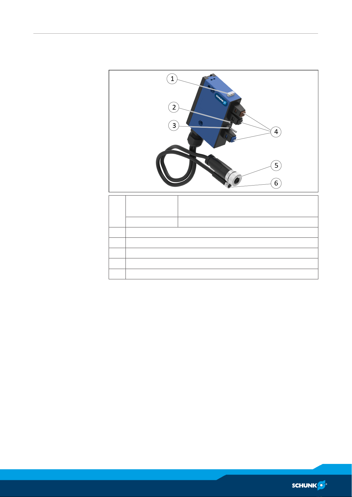
4 Design and description
4.1 Design
1 Green/red LED green: operating voltage indicator
red: battery change signal
Orange LED Function display
2 ON button
3 PNP/NPN switch
4 Connections for sensors with open wire strands
5 Connection for sensor with M12 connecting plug
6 Connection for sensor with M8 connecting plug
4.2 Description
The SST sensor tester enables the rapid testing and adjustment of
inductive sensors, magnetic switches and reed contacts.
The switching function is signaled by an LED and an additional
acoustic signal.
When not in use, the sensor tester automatically switches itself off
after approx. 30seconds.
The necessary power is supplied by a 9V compound battery

Assembly
8
04.00 | SST | Assembly and operating manual | en | 389581
5 Assembly
The Sensor tester SST can be fastened by means of the lateral
through-bores if necessary.
1 Through-bores Ø 5.5

Operation
04.00 | SST | Assembly and operating manual | en | 389581
9
6 Operation
6.1 Installation of a sensor on the sensor tester
6.1.1 Connection of a sensor with connection plug
ØPlug the M8 or the M12 plug of the sensor into the according
socket of the SST.
ØTighten the knurled nut.
6.1.2 Connection of a sensor with an open wire strand
Wire colors
for the sensor
Color of SST spring-
type terminal
Description
Brown Brown (+ PLUS) Supply voltage of the
sensor + VDC
Black / White Black (A) Sensor signal output
Blue Blue (– MINUS) Supply voltage of the GND
sensor
ØCheck whether the wire colors of the sensor correspond to the
descriptions in the table.
ØConnect wires to the spring-type terminals.
6.2 Operation of the SST with a sensor
■The sensor to be tested is connected.
ØAdjust PNP/NPN switch(1) according to the sensor type.
ØActuate the ON button(2).
✓LED(3) lights up green.
✓If the LED(3) lights up in red, the battery needs to be
changed.
ØIf the sensor is damped, the SST emits a signal and the LED(4)
lights up in orange.
ØIf the status of the sensor changes from damped to undamped,
the SST emits a signal again and the LED(4) goes off.
NOTE
After switching on, the SST remains active for 30 seconds. Every
change of state of the sensor extends the activation duration
another 30seconds.

Maintenance and care
10
04.00 | SST | Assembly and operating manual | en | 389581
7 Maintenance and care
7.1 Maintenance
This product does not require maintenance.
7.2 Battery change
Ø
Using a screwdriver, press against the lock on the cover of the
battery compartment and open the battery compartment cover.
ØRemove old batteries and dispose of them properly.
ØInsert new battery.
Battery type: 9V compound battery 6LR61
Ø
Close the battery compartment cover and snap the lock in place.
Table of contents
Other SCHUNK Test Equipment manuals


