Svantek SV258 PRO User manual

USER MANUAL
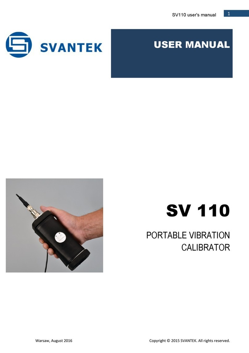
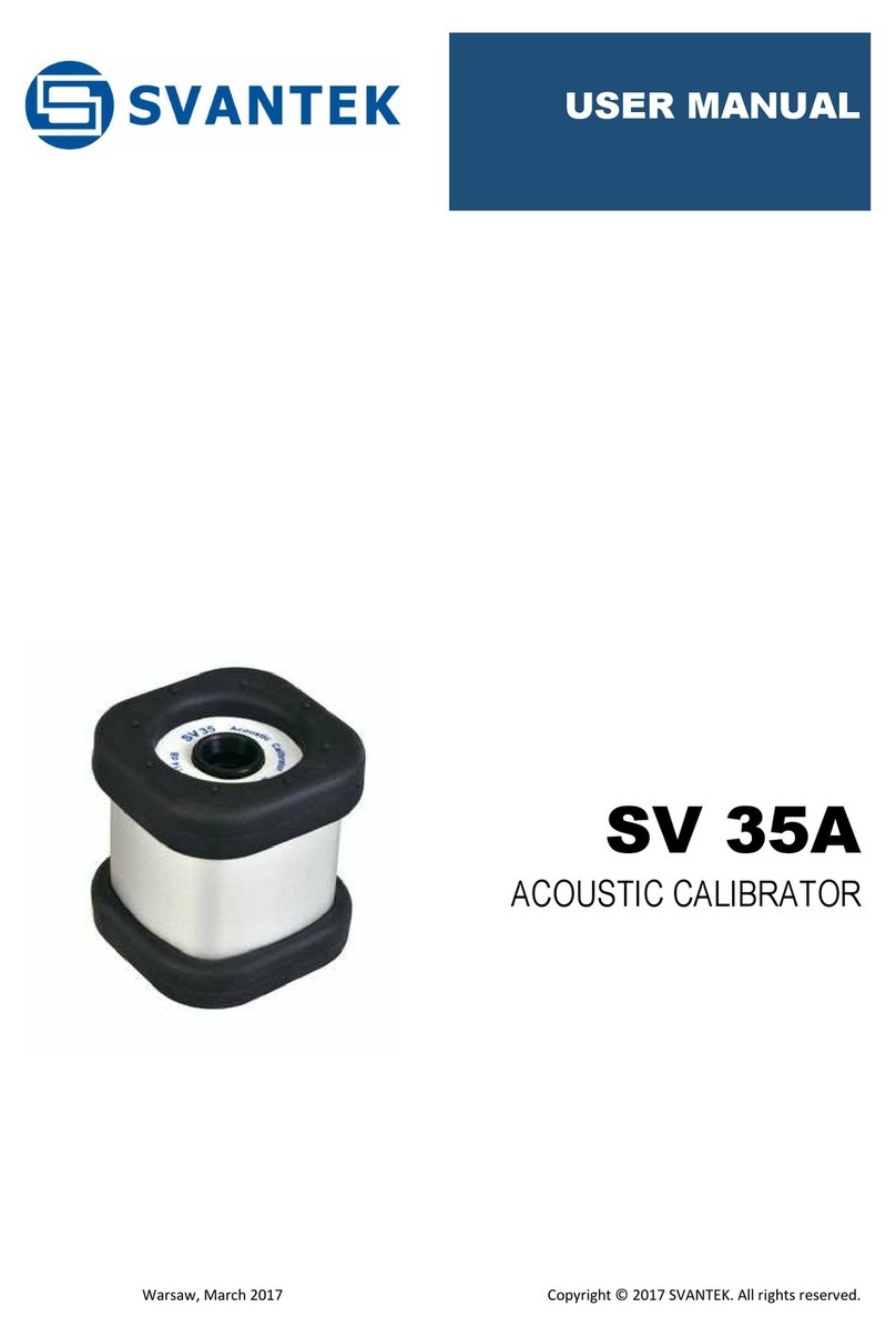
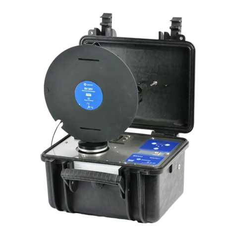
Warsaw, 2021-05-15
Rev. 2.00
Copyright © 2021 SVANTEK.
All rights reserved.
SV 258 PRO
BUILDING VIBRATION &
NOISE MONITORING
STATION

SV 258 PRO User Manual
2
Note: Because of continuous product improvement SVANTEK reserves the right to make
changes to product specifications without notice. To download the most up to date user's
manual please visit our web site at www.svantek.com.
This user manual presents the controller firmware revision SD270-PRO v6.03 and SD270A-
PRO v3.04.
The succeeding software revisions (marked with the higher numbers) can change the view of
some displays presented in the text of the manual.
WEEE Notice: Do not throw the device away with the unsorted municipal waste at the end
of its life. Instead, hand it in at an official collection point for recycling. By doing this you will
help to preserve the environment.
The software described in this manual is furnished under a license agreement and may be used only in
accordance with the terms of that agreement.
Copyright Notice
Copyright © 2021 Svantek Sp. z o.o.
All rights reserved.
Reproduction without permission is prohibited.
Trademarks
Trademarks or registered marks in this manual belong to their respective manufacturers.
Microsoft and Windows are registered trademarks of Microsoft Corporation.
Disclaimer
Information in this document is subject to change without notice and does not represent a commitment
on the part of Svantek.
Svantek provides this document “as is,” without warranty of any kind, either expressed or implied,
including, but not limited to, its particular purpose. Svantek reserves the right to make improvements
and/or changes to this manual, or to the products and/or the programs described in this manual, at any
time.
Information provided in this manual is intended to be accurate and reliable. However, Svantek assumes
no responsibility for its use, or for any infringements on the rights of third parties that may result from its
use.
This product might include unintentional technical or typographical errors. Changes are periodically
made to the information herein to correct such errors, and these changes are incorporated into new
editions of the publication.
Technical Support Contact Information:
web: www.svantek.com
e-mail: office@svantek.com.pl

SV 258 PRO User Manual
3
IMPORTANT NOTES BEFORE USE
✓Only SVAN 958A and the controller can be disconnected and removed from the station case by the user.
All other disassembling work should be performed strictly by an authorized service team.
✓The producer does not recommend removing the controller without a sound reason. Double check that
the controller has a good fixation in the connector after reconnecting.
✓Do not remove the battery from the case! This operation must be done only by the authorised service.
✓SVAN 958A is powered from the external source and doesn’t use its internal batteries. Internal
instrument’s batteries must be removed for correct system operation and safety reasons.
✓The correct connection of the accelerometer or microphone is not signalled by the controller therefore it
is recommended to perform a test measurement each time the station is turned on.
✓During station operation it is recommended to charge the internal and external batteries as often as
possible; this will extend battery life. It is necessary to charge the battery after any total discharge.
✓Monitoring station and/or SB 272 should not be stored for a long time with discharged batteries. Storing
with batteries in discharged condition may damage them.
✓If Monitoring station and/or SB 272 are planned to be stored for a long period of time, it is recommended
to charge their batteries to 100% capacity. Batteries should be charged at least once per 6 months.
✓If the storage period is longer than one year, a discharge/charge cycle must be performed. To do this,
leave the device turned on until the battery is completely discharged. Then charge the battery to 100%
capacity.
✓Monitoring station and SB 272 have their own chargers, which are incompatible: SB 270 is a waterproof
power supply for SV 258 PRO, whereas SB 273 is an indoor charger for SB 272.
✓If you use the SV 208A sound measurements set, before installing the station at the measurement site,
make sure that the protective caps on the four anti-bird spikes of the SA 277 outdoor microphone
protection kit are removed. It is recommended to use the protective caps during transportation, storage
and other operations with the instrument like, laboratory calibration, etc. to avoid personal injury.
✓The windscreen influences the free-field characteristics of the SA 277 outdoor microphone protection kit;
therefore, it is important to check its condition regularly. In the case of visible degradation of the foam
surface it must be replaced by the new one.
✓If you use desiccator (silica gel) inside the outdoor microphone protection, it should be regenerated after
some period of use, when it changes colour to light grey, by drying it for 3 hours in a temperature of 150°C.
Desiccator should be inspected at least every two weeks, and more often when used in conditions of high
air humidity.

SV 258 PRO User Manual
4
Table of Contents:
IMPORTANT NOTES BEFORE USE .......................................................3
1INTRODUCTION.................................................................................6
1.1 Features............................................................................................................................6
1.2 Accessories included.......................................................................................................7
1.3 Accessories available......................................................................................................7
1.4 Software options available ..............................................................................................7
2MONITORING STATION SET............................................................8
2.1 SV 258 PRO standard set and optional elements...........................................................8
2.1.1 Waterproof case........................................................................................................9
2.1.2 Controller................................................................................................................11
2.1.3 Sound and Vibration Analyser.................................................................................13
2.1.1 Mobile modem ........................................................................................................15
2.1.2 Building / Ground Vibration Accelerometer ..............................................................15
2.1.3 External Power Supply with AC/DC converter..........................................................16
2.2 Optional accessories for SV 258 PRO...........................................................................16
2.2.1 Sound Measurement Set.........................................................................................16
2.2.2 Vibration Calibrator .................................................................................................17
2.2.3 Sound Calibrator.....................................................................................................17
2.2.4 External rechargeable battery..................................................................................18
2.2.5 Solar Panel.............................................................................................................18
2.2.6 SP 272 –Alarm Lamp.............................................................................................19
3OPERATING THE STATION............................................................20
3.1 Powering.........................................................................................................................20
3.2 Controller interface ........................................................................................................20
3.3 Modes of station operation............................................................................................21
3.3.1 Operational mode....................................................................................................21
3.3.2 Battery charging mode............................................................................................22
3.3.3 Bootstrap mode.......................................................................................................22
3.4 Establishing mobile connection....................................................................................22
3.5 Assembling the station..................................................................................................23
3.6 Turning on the station....................................................................................................25

SV 258 PRO User Manual
5
4REMOTE CONTROL VIA MOBILE CONNECTION ........................26
4.1 SvanNET webservice .....................................................................................................26
4.2 Interface functionalities of mobile modem....................................................................27
4.2.1 Main communication channel..................................................................................28
4.2.2 SMS / E-mail alarming.............................................................................................29
4.2.3 SMS command exchange .......................................................................................29
4.3 Remote Communication module of SvanPC++.............................................................29
5SVANNET USER INTERFACE ........................................................30
5.1 Station list view..............................................................................................................30
5.1.1 STATUS view..........................................................................................................32
5.1.2 LOG views..............................................................................................................34
5.2 WEB INTERFACE view...................................................................................................35
5.2.1 Live data view.........................................................................................................36
5.2.2 Configuration views.................................................................................................37
5.2.3 STATUS view..........................................................................................................45
5.2.4 DATA FILES view ...................................................................................................45
6SV 258 PRO MONITORING STATION TECHNICAL DATA...........46
7LIST OF RELATED DOCUMENTS..................................................49

SV 258 PRO User Manual
6
1 INTRODUCTION
SV 258 PRO is an outdoor monitoring system based on the
SVAN 958A class 1 vibration and sound four-channel level
meter dedicated for ground and building vibration
applications. The portable and battery powered station can
be used for a variety of monitoring applications including
construction site monitoring, tunnelling and blasting.
The IP 67 rated case contains a lead-acid battery which
operating time can be easily extended by connecting an
external battery or a solar panel. The intelligent charging unit
allows to use a solar panel without expensive controllers and
heavy batteries.
The station case is fitted with very robust, waterproof
connectors (military standard) and comes with an IP 65
external power supply. The system uses a low-noise,
hermetically sealed tri-axial piezoelectric accelerometer
enabling the outdoor use without additional enclosures. The
accelerometers' signal ground is insulated from themounting
surface and outer case to prevent ground loops. All
accessories fit conveniently into a second carrying case.
The monitoring station uses the mobile modem for the remote communication with the Internet. SvanNET,
a relay server, supports the connection between PC and the station allowing the usage of all types of SIM
cards, regardless if they have public or private IP. The use of SvanNET gives access to the status of the
monitoring station also via mobile phone or tablet.
SV 258 PRO may be delivered with two firmware versions of SVAN 958A.
The basic firmware of SVAN 958A is dedicated for general four channel measurements and the user may
configure all channels independently. This firmware is supplied as a standard with SVAN 958A and can be
used for monitoring of vibration and sound levels when SVAN 958A is a part of the monitoring station
SC 258 PRO. This basic firmware has a so-called Ground Vibration option that allows simplified functions
for construction site monitoring.
The special firmware (SVAN 958AG) is dedicated for building vibration measurements and uses methods
based on Peak Particle Velocity and Dominant Frequency. Measurements of human vibration in buildings
are also possible as the instrument allows simultaneous measurement of velocity and acceleration of
vibrations with two independent steps of recording. In addition, it is possible to enrich the measurement with
Class 1 sound results.
Note: This manual describes SV 258 PRO comprising SVAN 958A with the basic firmware
(rev. 4.10.5).
1.1 FEATURES
•SV 258 PRO is a portable monitoring station housed in an IP 67 waterproof case dedicated for
periodic outdoor measurements.
•Human Vibration in buildings measurements in accordance with ISO 2631-1, BS 6472 and
DIN 4150-2.
•The station is based on the SVAN 958A instrument which can be easily removed fromthe case and
used as a hand-held sound and vibration level meter and analyser.
•Class 1 noise measurements are performed over a very wide dynamic range over 110 dB from
3 Hz up to 20 kHz.
•Time history of measurement results is saved in the file.
•The station canperform a real-time frequency analysis in 1/1 Octave or 1/3 Octave bands and save
spectra as Time history.

SV 258 PRO User Manual
7
•The mobile modem provides fast data transfer over the Internet to a PC with a standard Internet
connectivity.
•The remote communication settings are automatically adjusted to connect to the SvanNET Internet
service.
•The station can be powered from an internal battery, external battery or external DC power supply
and is ready for direct connection to a solar panel. The powering is managed by the intelligent
charging unit.
•The station uses a waterproof charger that is designed for the outdoor use.
•Military standard connectors provide reliable, robust and waterproof cable connections.
1.2 ACCESSORIES INCLUDED
SVAN 958A
Four channel Class 1 Sound & Vibration Analyser with the standard firmware
SM 258 PRO
Outdoor monitoring station for SVAN 958A including: 17Ah battery, mobile modem
(SP 270) and external power supply (SB 270)
SC 16
USB 1.1 cable
SC 61
TNC to BNC integrated connector
SV 207B
Building Vibration Measurement set including: triaxial accelerometer 1000 mV/g (SV
84), mounting adapter with special levelling system
SC 278
Cable for SV 84 and SV 258
SA 251
Carrying case for SV 207B, SB 270 and accessories to SV 258
1.3 ACCESSORIES AVAILABLE
SV 208A
Sound measurements set: Microtech Gefell Prepolarised condenser microphone
(MK 255), microphone preamplifier (SV 12L), outdoor microphone kit (SA 277),
desiccator (SA 270D), preamplifier cable (SC 277), carrying case (SA 250)
SV 36
Class 1 sound calibrator: 94/114 dB@1000 Hz
SV 111
Vibration Calibrator for HVM
SB 272
External battery for SV 27x monitoring stations series (33 Ah) including indoor
charger
SB 271
Solar panel for SV 258 monitoring station (40 W)
SA 206
Mast with adjustable height from 1.5 meter to 4 meters
SP 272
Light and sound alarm, 12V DC
1.4 SOFTWARE OPTIONS AVAILABLE
The standard firmware of SVAN 958A includes Level Meter function only. Other functions are optional:
SF 258_1
1/1 octave analysis option
SF 258_2
1/3 octave analysis option
SF 258_3
1/1 & 1/3 octave analysis option
SF 258_4
FFT analysis option
Note: The software options for the instrument can be purchased at any time as only the
introduction of a special unlock code is required for their activation in a specific instrument.
Contact your local Svantek distributor for further information and costs for these options.

SV 258 PRO User Manual
8
2 MONITORING STATION SET
2.1 SV 258 PRO STANDARD SET AND OPTIONAL ELEMENTS
The SV 258 PRO station consists of two carrying
cases. The main case is waterproof with the internal
17 Ah battery and internal charging block providing
power from an external DC power supply or a solar
panel. The SVAN 958A Class 1 vibration and sound
level meter is installed inside the main case but can
be removed and used as a hand-held meter.
The outdoor charger and vibration accelerometer
are packed inside the second carrying case.
The SV 258 PRO station includes:
•waterproof case with battery, charging unit
and connectors (1),
•controller (2),
•SVAN 958A –Class 1 Vibration & Sound
Level Meter and Analyser (3),
•mobile modem (4),
•low-noise, hermetically sealed tri-axial
piezoelectric accelerometer enables an
outdoor use without additional
enclosures (5),
•accelerometer mounting adapter (8) and
•power supply unit.
The waterproof case is equipped with:
•external power connector (6),
•external interface connector (7),
•air pressure compensation valve (9)
•two input signal connectors (10).
The power supply unit (11) and vibration
accelerometer (5) are packed inside the second
transportation case together with the mounting
adapter (8).
Additional accessories for the SV 258 PRO system, not included in the standard set, but in many
applications, essential for reliable system operation and task performance are:
1
2
3
5
4
5
11
8
6, 7
8
10
9

SV 258 PRO User Manual
9
1. Outdoor sound measurement set (SV 208A)
-see Chapter 2.2.1,
2. Vibration field calibrator (SV 111)
-see Chapter 2.2.2,
3. Sound calibrator (SV 36)
-see Chapter 2.2.3,
4. External battery 33 Ah including indoor charger
(SB 272)
-see Chapter 2.2.4,
5. Solar panel 40 W (SB 271)
-see Chapter 2.2.5,
6. Light and buzz alarm lamp, 12V DC (SP 272)
-see Chapter 2.2.6,
7. Mast with adjustable height from 1.5 meter to 4
meters (SA 206)
-type:
Manfrotto
269BU.
2.1.1 Waterproof case
The SV 258 PRO waterproof case (IP 67) houses and protects the
main elements of the monitoring station:
•controller,
•mobile modem,
•SVAN 958A instrument,
•other internal elements such as: rechargeable battery,
connectors, cables, circuit boards.
SVAN 958A can be removed from the case by the user and used
as a hand-held vibration and sound meter.
To do this the user should:
1. switch off SVAN 958A by pressing together the <Alt> and
<Start/Stop> keys,
2. unscrew the input connector and disconnect the input
cable from SVAN 958A,
3. disconnect the USB and power cables from SVAN 958A.
The controller is fixed in the station case by a Signal Power Combo
connector and can also be removed from the case. To do this, pull
the controller up and remove it from the slot.
To put it back, put the controller in the slot and press on it to
achieve a good fixation with the connector.
Note: Only SVAN 958A and the controller can be disconnected and removed from the station
case by the user. All other disassembling work should be performed strictly by an authorized
service team.

SV 258 PRO User Manual
10
Note: The producer does not recommend removing the controller without a sound reason.
Double check that the controller has a good fixation in the socket after reconnecting!
The monitoring station case is equipped with the air pressure
compensation valve that enables you to open the case easily if the
internal pressure is lower than the atmospheric one.
Use the silica gel bags (optional accessory) for absorbing any
remaining moisture after closing the lid.
The valve should be released if opening the top lid is problematic.
Note: The valve must be closed when the station is used outdoors, otherwise the case is not
sealed against moisture.
The station case is equipped with four Souriau UTO type connectors for:
•input signals from thetri-axial piezoelectric accelerometer
(INPUT 1-3),
•input signal from the microphone (INPUT 4),
•powering station and charging the internal battery
(DC SUPPLY),
•external interface for the digital input/output
(EXTERNAL INTERFACE). In the standard station
configuration, this socket can be used for alarm signals
output (for example, SP 272light and sound alarm).
To connect a cable to a case socket, start by lining up the key on
the plug and socket, then lock the connector by turning the ring
clockwise (only the ring close to the socket will rotate).
To disconnect a cable, push the connector towards the station and
turn it counter clockwise. New connectors require more force so
using a closed hand is more effective than using only fingers.

SV 258 PRO User Manual
11
The station is equipped with a Lead-Acid rechargeable battery
(17Ah, 12V), located in the bottom of the case.
The battery can be used in any chosen position without the risk of
leakage. The battery has a pressure relief valves that allows safe
dispersal of any excess pressure inside the cell (VRLA).
Battery capacity may vary depending on the ambient temperature.
The safetyfuse is located on theleft side ofthe controller connector
plate.
Note: Do not remove the battery from the case! This operation must be done only by the
authorised service.
Note: Battery is not restricted for air, surface and water transport. Classified as non-hazardous
material (IATA/ICAO Special Provision A67, DOT-CFR Title 49 parts 171-189, IMDG
amendment 27).
Note: During station operation it is recommended to charge the internal battery as often as
possible; this will extend battery life. It is necessary to charge the battery after any total
discharge.
Note: The station should not be stored for a long time with a discharged battery. Storing with
batteries in discharged condition may damage them.
Note: Ifthe station is planned to bestored fora long period oftime, it is recommended tocharge
its battery to 100% capacity. The battery should be charged at least once per 6 months.
Note: If the storage period is longer than one year, a discharge/charge cycle must be
performed. To do this, leave the device turned on until the battery is completely discharged.
Then charge the battery to 100% capacity.
The case lid is equipped with an antenna for the mobile modem.
2.1.2 Controller
The SV 258 PRO monitoring station is equipped with the
SD 270A PRO (or previous modification SD 270 PRO without the
TEST button and corresponded LED) controller that integrates and
controls all system modules and is responsible for the powering of
all elements and communication between the following elements
of the monitoring station:
•SVAN 958A instrument,
•mobile modem
and optionally
•light and sound alarm etc.

SV 258 PRO User Manual
12
Very important task of the controller is power distribution - it provides appropriate DC power to every
element of the system (managing external power sources such as the SB 270 power supply or an optional
solar panel or an external battery).
Another key task of the controller is the integration of the entire system –examining the communication,
state and condition of every module of the system and the immediate indication of all problems on the
control panel by means of several LEDs or remotely using the mobile Internet connection.
The controller also analyses the temperature condition inside the monitoring station case. If the internal
temperature is higher than +50oC, the controller will switch off internal battery charging. If the temperature
further increases over +65oC, the controller will switch off the monitoring station. The station will be also
switched off if the internal temperature falls below -30oC.
The TEST key in the SD 270A PRO controller allows you to reset the controller settings. To do this, press
and hold the TEST key for more than 20 seconds until the corresponding LED lights up. Release the key
and the controller will be reset.
The mini USBconnector on thefront panel of the controller is intended for updating thecontroller firmware.
Note: The mini USB connector on the controller panel doesn’t provide any measurement or
setup data exchange with the PC. Such data exchange is carried out via the USB Device
interface of SVAN 958A (USB socket).
Note: Communication of the controller or SVAN 958Awith a PCrequires installation of the USB
drivers on your PC. USB drivers for Svantek devices are available on
http://svantek.com/support-drivers-software.html
Note: Make sure SvanPC ++ is Off before starting the update! If not, please Exit it before
starting any upgrading.
To upgrade the SD 270 PRO controller firmware, go through the next steps:
1. If you upgrade the firmware without removing the controller switch off SVAN 958A and wait until
all LEDs are off.
2. Connect the controller to the PC with the SC 56 cable.
3. Run the “loadfile.bat” file on the connected PC. This operation opens a window which displays the
state of downloading the program. After successful loading the “File loaded” will be displayed.
4. Press any key on the PC to finish firmware download.
5. Disconnect the SC 56 cable. The BAT 1 LED goes out.
To upgrade the SD 270A PRO controller firmware, go through the next steps:
1. If you upgrade the firmware without removing the controller switch off SVAN 958A and wait until
all LEDs are off.
2. Connect the controller to the PC with the SC 56 cable. The TEST LED starts blinking red 1 per
second.
3. Run the “loadfile.bat” file on the connected PC. This operation opens a window which displays the
state of downloading the program. While downloading the TEST LED starts blinking faster. After
successful loading the “File loaded” is displayed and TEST LED starts blinking red 1 per 3
seconds.
4. Press any key on the PC to finish firmware download.
5. Disconnect the SC 56 cable. The TEST LED goes out.
Note: If after successful firmware loading you run the “loadfile.bat” file again, the firmware will
not start downloading and the byte counter will not be changing. If you still would like to repeat
firmware upgrading, disconnect the SC 56 cable and repeat steps from 2 to 5.
Note: In the case of any problems with upgrade, switch off SVAN 958A and wait until all LEDs
are off, then extract the controller from the case and repeat steps from 2 to 5.

SV 258 PRO User Manual
13
2.1.3 Sound and Vibration Analyser
SVAN 958A is a class 1 Four-channel Sound & Vibration level
meter as well as a real time 1/1 or 1/3 octave or FFT analyser and
is a core of the SV 258 PRO system. Its role is to make
measurements and save results in files, as well as to control data
transfer via the mobile modem to the SvanNET webserver or
directly to a PC. Measurement results can be analysed with the
use of the SvanPC++ software.
Main important features of SVAN 958A as a part of the
SV 258 PRO system:
•Four-channel, 20 kHz real-time, simultaneous sound and
vibration measurements: Human Vibration measurements
meeting ISO 8041-1:2017 including VDV and MTVV and
Sound level meter class 1, IEC 61672:2002.
•Analyser options: FFT analysis up to 1600 lines in 20 kHz
band; 1/1 and 1/3 octave real-time analysis.
•Advanced time history logging, time-domain signal
recording for each channel provides complete information
about the measured signal.
•Advanced trigger and alarm functions.
SVAN 958A has twoinput sockets: 4-pins Lemo compatible socket
type ENB.0B.304 for Channels 1–3and TNC for Channel 4.
All sockets ensure IEPE power supply for the accelerometers or
microphone preamplifiers.
SVAN 958A, when it works with the monitoring station, is powered
from an external power supply via the 6-24V socket.
Data transfer to the modem is via a USB Host socket, the serial
interface.
Other instrument sockets are not used in the SV 258 PRO system.
not used
serial port
external power
Note: As a part of the SV 258 PRO station SVAN 958A is powered from the external source and
doesn’t use its internal batteries. Internal instrument’s batteries must be removed for correct
system operation and safety reasons!
Note: The station is delivered without internal batteries inside the instrument. But if you use
SVAN 958A as a hand-held instrument, don’t forget to remove batteries from the instrument
every time you put it back into the station slot.
To insert or extract batteries,
switch off the instrument,
remove the bottom rubber
cover, unscrew out the
blanking plate and slide the
batteries out. Screw the
blanking plate and fix the
rubber bottom cover back on.

SV 258 PRO User Manual
14
There are some important settings, which should be assured in the instrument when it is a part of the
monitoring station:
1. Network Setup should be set to GPRS to enable data
transmission via the mobile modem (path: <Menu> / Setup /
Wireless Com. / Network Setup).
2. RS232 should be switchedon in the USB Host Setup window
(path: <Menu> / Setup / USB Host Setup).
3. The RS232 should have parameters (path: <Menu> / Setup /
RS232 Setup):
•Baud Rate: 115200
•Time Out: 1s.
Other settings of the RS232 may cause improper communication
with the modem.
Note: Without these settings, the instrument will not communicate with the mobile modem!
You may adjust the input parameters of four station channels in accordance with measurement purposes
and used transducers (see SVAN 958A User Manual).
If you are going to use the station for measurement of the vibration imission in accordance with
DIN 45669-2 and optionally to monitor noise, you must assure additional settings:
1. The measurement function should be set to
Ground Vibrations (path: <Menu> / Function /
Measurement Function), which automatically defines next
channel’s assignment:
Channel 1: Vibration
Channel 2: Vibration
Channel 3: Vibration
Channel 4: Sound
2. If you are going to use the optional SV 208A Sound
measurements set, you should set the Outdoor filter as
Microphone Correction for the forth channel (path: <Menu>
/ Input / Channels Setup / General Setup (P1) / Channel 4 /
Microphone Correction). This filter is dedicated for the
permanent outdoor monitoring application. Frequency
characteristics of the filter is given in Appendix C to the
SVAN 958A User Manual.
Note: See also SVAN 958A User Manual for measurement and instrument settings.
All measurement, hardware and data transmission settings can be set up via the SVAN 958A user
interface, or remotely via the SvanNET webserver or the SvanPC++ program.

SV 258 PRO User Manual
15
2.1.1 Mobile modem
The SP 270 mobile modem provides fast data transfer over the
Internet to a PC with standard Internet connectivity. The station
uses a 3G modem type “Gemalto®EHS6T Terminal” or a 4G
modem type “Cinterion®PLS62T-W Gateway”.
Both modems use mini-SIM cards 25mm x 15mm with Internet
Access. The SIM slot accepts 1.8V and 3V SIM cards in
accordance with GSM 11.12 Phase 2.
Note: See also “Gemalto®EHS6T Terminal” or “Cinterion® PLS62T-W Gateway” user manual.
The SIM-card should be inserted in the slot with the circuit side
facing left by pushing it until it snaps hold.
The SIM-card can be removed from the card slot by using a pen or
other flat object. Press on the card until it snaps out. Use tweezers
to remove the SIM-card from the slot.
If settings of SVAN 958A in the “Wireless Transfer” menu are correct, then once you insert a SIM card in
the modem slot the remote communication settings of the modem are automatically adjusted to connect
to the SvanNET server. In some cases, APN should be provided.
Note: Be sure that the PIN of the SIM card is off!
2.1.2 Building / Ground Vibration Accelerometer
The SV 84 low-noise, hermetically sealed triaxial piezoelectric
accelerometer is designed to monitor building and ground
vibrations with the SVAN 958A instrument.
The hermetically sealed glass connector protects SV 84 from
harmful dust and moisture enabling the outdoor use without
additional enclosures.
The signal ground is insulated fromthe mountingsurface and outer
case to prevent ground loops.
SV 84 is a part of the SV 207B set that includes also the metal
mounting adapter.
Note: See SA 84 Technical Specification on www.svantek.com.
Note: Correct connection of the accelerometer is not signalled by the controller, therefore it is
recommended to perform test measurements each time the station is turned on.

SV 258 PRO User Manual
16
2.1.3 External Power Supply with AC/DC converter
The SB 270 external power supply is a waterproof Single Output
Switching Power Supply which is characterised by:
•Universal AC input / Full range (90 ~ 264VAC)
•Protections: Short circuit / Over load / Over voltage
•Fully encapsulated with IP65 level
•Fully isolated plastic case
2.2 OPTIONAL ACCESSORIES FOR SV 258 PRO
2.2.1 Sound Measurement Set
The SV 208A sound measurements set includes: Microtech Gefell
Prepolarised condenser microphone (MK 255), microphone
preamplifier (SV 12L), outdoor microphone kit (SA 277),
desiccator (SA 270D), preamplifier cable (SC 277) and carrying
case (SA 250). The outdoor microphone kit protects the
preamplifier and microphone from weather conditions. The use of
the outdoor kit requires an extension cable between the monitoring
station and the microphone preamplifier (SC 258). SA 277 is made
of lightweight materials and is easy to install on a tripod.
The outdoor microphone kit has ¾” screw on its bottom which
enables using of standard tripods or other user specific mountings.
Technical data such as direct and frequency characteristics
associated with the microphone are specified in the SVAN 958A
user manual.
Optionally you may use desiccator - Silica gel. Desiccator absorbs
moisture normally contained in the air.
Note: Desiccator should be regenerated after some
period of use, when it changes colour to light grey, by
drying it for 3 hours in a temperature of 150°C. Desiccator
should be inspected at least every 2 weeks, and more
often when used in conditions of high air humidity.
Note: See Appendix B to learn how to assemble and
disassemble the outdoor microphone kit.
Note: After assemblingthe SA 208A or after calibration
check that the windscreen foam is properly installed. It
should be shifted close to the anti-bird spikes. Otherwise
the SA 208A free-field characteristics will be different
from declared ones.
For absolute certainty, push the windscreen up to the
stop.

SV 258 PRO User Manual
17
Note: Before installing the station at the measurement
site, make sure that the protective caps on the four
antibird spikes are removed.
It is recommended to use the protective caps during
transportation, storage and other operations with the
instrument like, laboratory calibration, etc. to avoid
personal injury.
Note: Correct connection of the microphone is not signalled by the controller therefore it is
recommended to perform a test measurement each time the station is turned on.
2.2.2 Vibration Calibrator
The SV 111 vibration calibrator is designed for in-situ checks
according to ISO 8041-1:2017. In-situ checks are intended for
application in the field prior to and following a measurement or
series of measurements.
The SV 111 is suitable for calibration checks of various of vibration
transducer types at different frequencies from 16 Hz up to 640 Hz.
Depending on the selected frequency you may choose the level of
the calibration from 1 m/s2to 10 m/s2.
SV 111 has robust casing and built-in rechargeable battery.
To calibrate or check the measurement system with the SV 84
accelerometer the special SA 154 calibration adapter is needed.
This adapter is optional, not included in the monitoring station
standard set.
2.2.3 Sound Calibrator
The SV 36 1 Class Sound calibrator produces sound pressure of
declared levels - 94 or 114 dB at a frequency of 1 kHz.
This calibrator is equipped with the autorun function. It starts
generation of the declared sound pressure automatically after
insertion of the microphone into the calibrator hole.

SV 258 PRO User Manual
18
2.2.4 External rechargeable battery
SB 272 is an external source of DC power for the monitoring
station. It includes a Lead-Acid rechargeable battery (33 Ah, 12 V)
and is dedicated for outdoor use because of its waterproof case.
The battery capacity enables up to three times longer operating
time of the monitoring station.
The SB 272 set includes the SB 273 indoor charger and a cable
for connection between SB 272 and the monitoring station.
SB 272 has the same connector for charging and for power supply and therefore cannot be used as a
power supply for the monitoring station and at the same time be charged (as the internal station battery
when it is charged from the solar panel or external power supply).
Note: SB 272 cannot be charged by the monitoring station SB 270 power supply!
Note: SB 272 is not restricted for air, surface and water transport. Classified as non-hazardous
material (IATA/ICAO Special Provision A67, DOT-CFR Title 49 parts 171-189, IMDG
amendment 27).
Note: It is necessary to charge SB 272 after any total discharge, otherwise the battery may lose
its capacity.
Note: SB 272 should not be stored for a long time with a discharged battery. Storing SB 272 with
a discharged battery may damage it.
Note: If SB 272 is planned to be stored for a long period of time, it is recommended to charge its
battery to 100% capacity. The battery should be charged at least once per 6 months.
Note: If the storage period is longer than one year, a discharge/charge cycle must be performed.
To do this, completely discharge the battery and then charge it to 100% capacity.
2.2.5 Solar Panel
The SB 271 solar panel (40 W, 17.5 V DC) extends the working
time of the monitoring station. The size and weight of the panel
enables easy transportation in the dedicated carrying bag.
The SB 271 solar panel does not require additional batteries or
external controllers.
The mounting system enables mounting of the SB 271 solar panel
above the monitoring case which provides a natural shade that
protects the station from overheating.
SB 271 is equipped with a military standard connector cable for
direct connection to the monitoring station.

SV 258 PRO User Manual
19
2.2.6 Alarm Lamp
TheSP 272 alarm lampis of typeWERMA, LED/Buzzer(12 V DC).
The alarm lamp is connecting to the EXTERNAL INTERFACE
connector.
In this lamp, the buzzer is disabled by default. To enable it:
1. open the case by pushing the black button and turning the
plafond and
2. shift the switch to the left.
2
1

SV 258 PRO User Manual
20
3 OPERATING THE STATION
3.1 POWERING
The SV 258 PRO monitoring station can be powered from:
•internal rechargeable battery,
•mains power source (SB 270);
and optionally from:
•external rechargeable battery (SB 272),
•solar panel (SB 271).
When the power supply is connected, it starts powering the station and charging the internal battery in
parallel (as a voltage source).
When the external rechargeable battery is connected to the station the station controller switches the
powering from the internal battery to the external one. As soon as the external battery is discharged the
controller switches powering back to the internal battery.
When the solar panel is connected to the station it starts loading the internal battery (as a current source).
And all the time the solar panel charges the internal battery, the station continues to be powered from the
internal battery.
The status of powering is indicated at the controller’s panel by a combination of DC, CHARGING, BAT 1
or BAT 2 LEDs (see Table below).
Note: It is recommended that the batteries of SV 258 PRO and SB 272 are charged before
going on site.
Note: The monitoring station and the external battery have their own chargers, which are
incompatible: SB 270 is a waterproof power supply for SV 258 PRO, whereas SB 273 is an
indoor charger for SB 272.
Note: SVAN 958A is powered from the external source and doesn’t use its internal batteries.
Internal instrument’s batteries must be removed for correct system operation and safety
reasons!
3.2 CONTROLLER INTERFACE
The controller interface consists of several LEDs, which indicate the state of the station elements or their
connection with the controller:
•DC –external power supply connection state (AC/DC converter),
•CHARGING –charging state of the internal battery,
•BAT 1 –internal battery state,
•BAT 2 –additional external battery state,
•SVAN –SVAN 958A connection state,
•3G –mobile modem connection state,
•EXT I/O –reserved.
Colour of LEDs can be red, orange or green. Colour of the SVAN and 3G LEDs reflect the communication
state with the corresponding unit. Colour of the DC, CHARGING, BAT 1 or BAT 2 LEDs depend on the
state of the power supply and charging of the internal battery.
The table below shows combinations of LED colours in the specific power supply conditions.
Other manuals for SV258 PRO
1
Table of contents
Other Svantek Test Equipment manuals
Popular Test Equipment manuals by other brands

Agilent Technologies
Agilent Technologies 11644A Series User's and service guide

Keysight Technologies
Keysight Technologies E6640A Getting started guide

Jinhan
Jinhan ADO102 manual

Millipore
Millipore Integritest Exacta Operating and maintenance manual

MSA
MSA ALTAIR Pump Probe operating manual

Anritsu
Anritsu 3656B W1 user guide