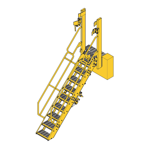
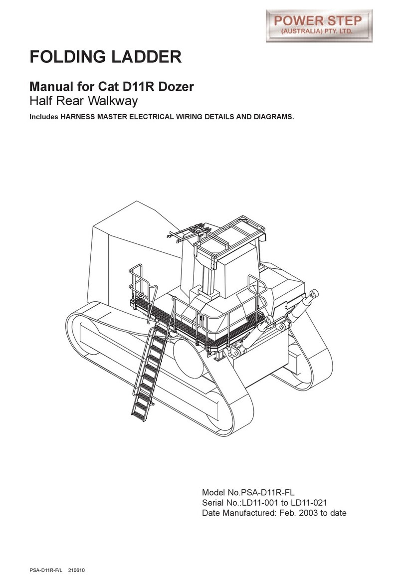
Power Step Cat D10R Dozer User manual

FOLDING LADDER
Manual for Cat D10R Dozer
Complete with Wrap-around Walkways
PSA-D10R FL+RHW 31-3-14
Model No.: PSA-D10R FL+RHWW
Serial No.: LD10RW-001 - ~
Date Manufactured: Oct 2006

Pg2
PSA-D10R FL+RHW 31-3-14
FOLDING LADDER
Caterpillar D10R Dozer
CONTENTS
Page 3Section 1 Installation and Mounting instructions
Installation Drawings
10 Section 2 Electrical System Wiring Diagrams
15 Section 3 Recommended Maintenance procedure
16 Section 4 Operating Procedure
Section 5 Drawings and Repair Parts lists
17 5 Assembly Complete
18 5-1 Ladder Assembly
Parts List
19 5-2 Landing Assembly LHS (+ NG Version)
Parts Lists
23 5-3 Landing Assembly RHS (+ NG Version)
Parts Lists
27 5-4 Landing Assembly Rear (+ NG Version)
Parts List
29 5-5 Spreader Assembly
Parts List
31 5-6 Drive Unit Assembly
Parts List
33 5-7 PROP Assembly
Parts List
34 5-8 Hydraulic Cylinder
Parts List
Valve Diagram
36 5-9 Power Pack
Parts List
39 5-10 Electrical Controls
Parts List
Material Kit Supplied

FOLDING LADDER
Caterpillar D10R Dozer
Pg3
PSA-D10R FL+RHW 31-3-14
NOTE
Follow all on-site/Mine lifting and safety procedures when installing
Power Step Ladder System to the Dozer.
Section 1
Installation and Mounting Instructions
See Drawing 22 053 (Page 4)
1. Remove grille plates from the rear of both mudguards. Remove the light and/or
horn from the rear of the left-side mudguard. Draw out wiring for future re-use.
2. Weld the Mounting Pads to the rear of the mudguards:
against the mudguard vertical inner plate and up against the mudguard top plate
(notch the inclined plate to suit to get the correct protrusion dimension), and
at the outer top corner of the mudguards, this time set against the mudguard plates
rather than in the corner. Fit the gusset piece to tie the Pad to the inclined plate.
3. Measure forward from the back edges of the mudguard plates and down from the
top surface of the mudguard tops (mudguard plate/s not any added non-slip
decking) to locate the side mounting pads. Weld these mounting pads in position.
Welding: Cat SP to AS1554
8 cfw

FOLDING LADDER
Caterpillar D10R Dozer
Section 1 Installation Instruction Drawings - 22 053
Pg4
PSA-D10R FL+RHW 31-3-14

FOLDING LADDER
Caterpillar D10R Dozer
Section 1 Installation Instruction Drawings - 22 054
See Drawings 22 054 - Page 6 & 7
Pg5
PSA-D10R FL+RHW 31-3-14
Procedure
1. Fit Mounting Blocks per Drg 22 053
2. Per REAR VIEW: Fit Spreader Plate 22 287 to rear mounting blocks. Use Washer
Plates 22.281 and washers under bolt heads.
3. Per VIEW 4A & 4B, Isolators: Fit Isolators 21 930 to Rear Spreader Plate. (See also
REAR VIEW). Per SIDE VIEW also fit Isolators 21 930 to Side Mounting Pads. On
left side fit Side Landing 22 017 with Ladder Shaft and Drive already assembled,
supported by Isolators. Fit Isolator Pin Bracket/s to arm at rear of landing beam with
pin to provide torsional restraint. Similarly fit Side Landing 22 016 on right side.
Note that there are two patterns of Isolator Pin Bracket bolted under the beams of
the Side Landings, 22 014 98 (shallow) at the rear and 22 014 99 (deep) at the
front. Both are orientated so the hole for the isolator pin is close to the machine
rather than away from the machine.
4. Fit Ladder. Using Spacers (within Actuator Cylinder Mounting 21 954), adjust drive
so gears are not loaded when ladder is lowered.
5. Per SIDE VIEW, REAR VIEW and VIEW 5, PROP System:
Attach PROP System Mounting Frame 22 0013 atop cabin, on ROPS unless similar
is already fitted by customer. Mount PROP 21 945 using middle holes (of set of 5).
Try Ladder with PROP. Ladder and PROP must align (longways with machine).
Adjust position of isolator mounting pads on frame if necessary then weld pads to
frame with 6cfw across top of frame rhs member ie where visible from above.
Adjust position of PROP (using choice of holes in set of 5) so ladder lies against
buffers when fully raised without loading the drive gears ie, with light manual effort
the ladder can be moved away from the buffers.
6. Per PLAN/SIDE/REAR VIEWS, fit Rear Walkway 22 051 & Handrails.
Pg6
PSA-D10R FL+RHW 31-3-14
FOLDING LADDER
Caterpillar D10R Dozer
Section 1 Installation Instruction Drawings - 22 054 Pg 1

Pg7
PSA-D10R FL+RHW 31-3-14
FOLDING LADDER
Caterpillar D10R Dozer
Section 1 Installation Instruction Drawings - 22 054 Pg2

FOLDING LADDER
Caterpillar D10R Dozer
Section 1 Drive Arrangement - 22 054 Pg 3
Pg8
PSA-D10R FL+RHW 31-3-14

FOLDING LADDER
Caterpillar D10R Dozer
Section 1 Installation and Mounting Instructions (cont.)
Maintenance Notes
Pg9
PSA-D10R FL+RHW 31-3-14
WARNING
Raising the POWER STEP ladder by external means can create a vacuum in the hydraulic
cylinder and create the opportunity to allow air into the hydraulic system, defeating the
inherent safety features of the POWER STEP.
This must be avoided, to maintain safe operation of the POWER STEP.
In instances where the use of external means to raise the ladder must be used, please
follow the following instructions:
Loosen hard plumbed hydraulic lines on cylinder side of lock valve on cylinder.
Raise ladder by available means.
Note: Make necessary arrangements to collect displaced oil, and be aware that air enters
the piston side of the cylinder as ladder is raised.
Lock in raised position.
Re-tighten hydraulic fittings.
SECURE THE LADDER IN THE RAISED POSITION, MECHANICALLY, CHAIN &
TAGOUT THE POWER STEP
To recommission the POWER STEP:
Loosen hydraulic fittings on cylinder side of lock valve.
Note: Collect displaced oil.
Lower ladder to lowest position, using alternate safety approved means, fully retracting
cylinder. Ensure all personnel are clear of step radius.
Operate electrical control switch to purge air from the hydraulic line systems, lock valve
and cylinder.
Tighten the hydraulic fittings either side of lock valve to restriction fitting.
Cycle step unloaded several times to purge all air from hydraulic system.
The Power Step will not operate correctly if there is any air in the hydraulic circuit (due to
the incorrect operation of the lock valve).
NOTE
Follow all on-site/Mine lifting and safety procedures when installing
Power Step Ladder System to the Dozer.

FOLDING LADDER
Caterpillar D10R Dozer
Section 2 Electrical System - Wiring Diagrams Page 1
Pg10
PSA-D10R FL+RHW 31-3-14

FOLDING LADDER
Caterpillar D10R Dozer
Section 2 Electrical System - Wiring Diagrams Page 2
Pg11
PSA-D10R FL+RHW 31-3-14
Non Auto-Raise

Pg12
PSA-D10R FL+RHW 31-3-14
FOLDING LADDER
Caterpillar D10R Dozer
Section 2 Electrical System - Wiring Diagrams Page 3 Auto-Raise
Toggle Switch Operated

Pg13
PSA-D10R FL+RHW 31-3-14
WIRING HARNESS 1
FOLDING LADDER
Caterpillar D10R Dozer
Section 2 Electrical System - Wiring Diagrams Page 4

Pg14
PSA-D10R FL+RHW 31-3-14
WIRING HARNESS 2
FOLDING LADDER
Caterpillar D10R Dozer
Section 2 Electrical System - Wiring Diagrams Page 5

Daily Visually check stairway and structure for damage, loose components,
handrails, etc.
Check for hydraulic oil leaks from hydraulic cylinders, plumbing and hoses.
Notify the appropriate supervisor for any observed damage or malfunction.
500 Hours
Grease the nipples on the rotation shaft and sector gears.
Check main mounting bolts for torque.
Check hydraulic oil level in power pack and top up as necessary. (Stairway in raised
position).
Top up using same hydraulic oil as used in hydraulics of machine.
Thoroughly check all electrical wiring for damage, replace as necessary.
Repeat daily check as above
5000 Hours
Change hydraulic oil in tank of hydraulic power pack (5.0 litres)
It is recommended that the same hydraulic oil be used in the power pack as the
hydraulics of the machine.
Grease 4 grease nipples on rotation shaft and sector gears, all of these are
accessible with the stairway lowered, and accessed from under the stairway.
Check and inspect all main bolts on stairway system.
Retorque if required.
Repeat daily check as above
FOLDING LADDER
Caterpillar D10R Dozer
Section 3 Recommended Maintenance Procedure
Pg15
PSA-D10R FL+RHW 31-3-14
NOTE.
THE RELIEF PRESSURE OF THE POWERPACK IS TO BE SET TO 2800PSI.
IF THE POWERPACK IS REPLACED,THIS RELIEF PRESSURE WILL NEED TO BE
RESET USING INLINE GAUGES.
FAILURE TO DO SO MAYRESULT IN ACCIDENT OR INJURY.

To Lower Ladder (from the machine)
Position machine in a level, safe area, away from the work face, whenever possible.
Apply park brake and lower engine speed to idle.
Check that the area below the Ladder Access System is clear of people and
obstacles, and lower ladder by operating the two position electrical switch adjacent
to the ladder, to the down position by pressing the switch down.
Hold the switch in the down position until ladder is fully lowered.
If the Dozer is parked on uneven ground, the bottom of the stairway may touch the
ground before the ladder is in the fully lowered position.
Should this occur, descend the ladder with caution.
To Raise Ladder
Ascend the ladder onto the landing of the Dozer.
Ensure the area around the ladder is clear of people and standing to the side, clear
of the area the handrails and ladder raises into, operate the electrical switch to the
raise position (up).
Hold the switch in the up position until the ladder is in the fully raised position.
The ladder is now raised and stored.
FOLDING LADDER
Caterpillar D10R Dozer
Section 4 Operating Procedure
Pg16
PSA-D10R FL+RHW 31-3-14
OPERATING NOTES
NOTE: FLOW CONTROL VALVE ADJUSTMENT:
The valve should be positioned to restrict the flow and speed of the Power Step when
lowering. Adjust the knob on top of the valve by turning left or right (clockwise) when the
step is being lowered, until it is lowering at a safe and reasonable speed.
When it is adjusted, lock the adjusting knob by tightening the grub screw located on the
side of the knob.
NOTE: MAGNETIC 'GO' SWITCH ADJUSTMENT:
The switch target trigger area is located on the opposite side and end from the cable entry
point on the switch. Once it is mounted to the switch bracket, adjust the switch in or out
from the stair steel trigger point, to be within 3mm - 10mm from touching each other when
the stair is in the desired rest position.
[DO NOT EXCEED 10mm DISTANCE BETWEEN THE SWITCH AND STRIKER PLATE].
Test by raising and lowering the Power Step a couple of times and adjust again if
necessary.

FOLDING LADDER
Caterpillar D10R Dozer
Section 5 Assembly Complete PSA-D10R-RHW
Pg17
PSA-D10R FL+RHW 31-3-14

FOLDING LADDER
Caterpillar D10R Dozer
Section 5-1 Ladder Assembly
Pg18
PSA-D10R FL+RHW 31-3-14
Item Part No. Part Name Qty
1
2
3
4
5
6
7
8
9
10
PS-22002
PS-22012
PS-21958
PS-21926-01
PS-21926-02
PS-21926-03
CPS-M12X45ZP
CPS-M12X30ZP
CPS-M12NZP
CPS-M12WH
LADDER & HANDRAIL FABRICATION
ROTATION SHAFT
PINION & KEEPER PLATE
LADDER SHAFT PIVOT BUSH-MIDDLE
LADDER SHAFT PIVOT BUSH-NON DRIVE END
LADDER SHAFT PIVOT BUSH- DRIVE END
BOLT-M12 x 45
BOLT-M12 x 30
NUT-M12
WASHER-M12
1
1
1
1
1
1
8
8
16
34
Set

FOLDING LADDER
Caterpillar D10R Dozer
Section 5-2 Landing Assembly LHS PS- 22017A
Pg19
PSA-D10R FL+RHW 31-3-14

FOLDING LADDER
Caterpillar D10R Dozer
Section 5-2 Landing Assembly LHS PS-22017A
See Drawing Page 19
Pg20
PSA-D10R FL+RHW 31-3-14
Item Part No. Part Name Qty
1
2
2A
3A
3B
4
5
6
7
8
9
10
11
12
13
14
15
16
17
18
19
20
21
22
23
24
PS-22017
PS-22010-A
PS-22010-B
PS-22014-98
PS-22014-99
PS-21930A
PS-21976
PS-21941
PS-21941-06
PS-21933
PS-21925
PS-22005-01
PS-22005-03/02
PS-22018-04
CPS-M12X75ZP
CPS-M12X65ZP
CPS-M12X35ZP
CPS-M12X30ZP
CPS-M12X25ZP
CPS-M8X35ZP
CPS-M12NZP
CPS-1/2”NN
CPS-M8NN
CPS-M12WH
CPS-1/2”WH
CPS-M8WH
LANDING ASSEMBLY
HANDRAIL-FRONT-LHS
HANDRAIL-REAR-LHS
ISOLATOR PIN BRACKET-REAR
ISOLATOR PIN BRACKET-FRONT
ISOLATOR MOUNTINGS ASSY.
FRONT PIVOT PIN BRACKET
ANTI VIBRATION BEARING
RUBBER BUSH
ISOLATOR BUSH PIN
MIDDLE BEARING MOUNTING
ANGLE BRACKET
ISOLATOR RUBBER/CLAMP
SIDE MOUNTING PAD
BOLT-M12 x 75
BOLT-SOCKET HEAD-M12 x 65
BOLT-M12 x 35
BOLT-M12 x 30
BOLT-M12 x 25
BOLT-M8 x 35
NUT-M12
NUT-NYLOC-1/2”UNC
NUT-NYLOC-M8
WASHER-HARDENED-M12
WASHER-HARDENED-1/2”
WASHER-HARDENED-M8
1
1
1
1
1
6
1
2
2
2
1
2
2
2
2
2
24
12
20
8
26
4
8
76
4
16
Other Power Step Ladder manuals

Power Step
Power Step PSA-EX3600-FRS User manual

Power Step
Power Step LeTourneau L1850 User manual

Power Step
Power Step Caterpillar 854G User manual

Power Step
Power Step PSA-EX2500-FRS User manual

Power Step
Power Step D10T User manual

Power Step
Power Step PSA-EX5500-FRS User manual

Power Step
Power Step PSA-K930E-FS User manual

Power Step
Power Step PSA-D11R-FL User manual

Power Step
Power Step Komatsu 960E User manual

Power Step
Power Step PSA-773D-FS User manual