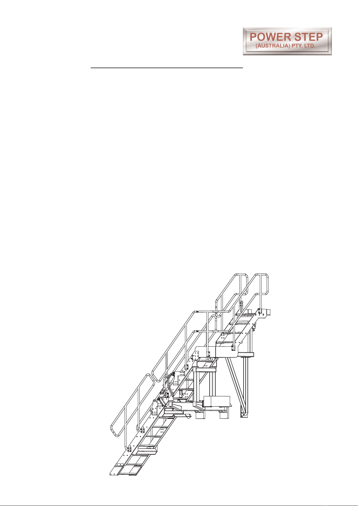
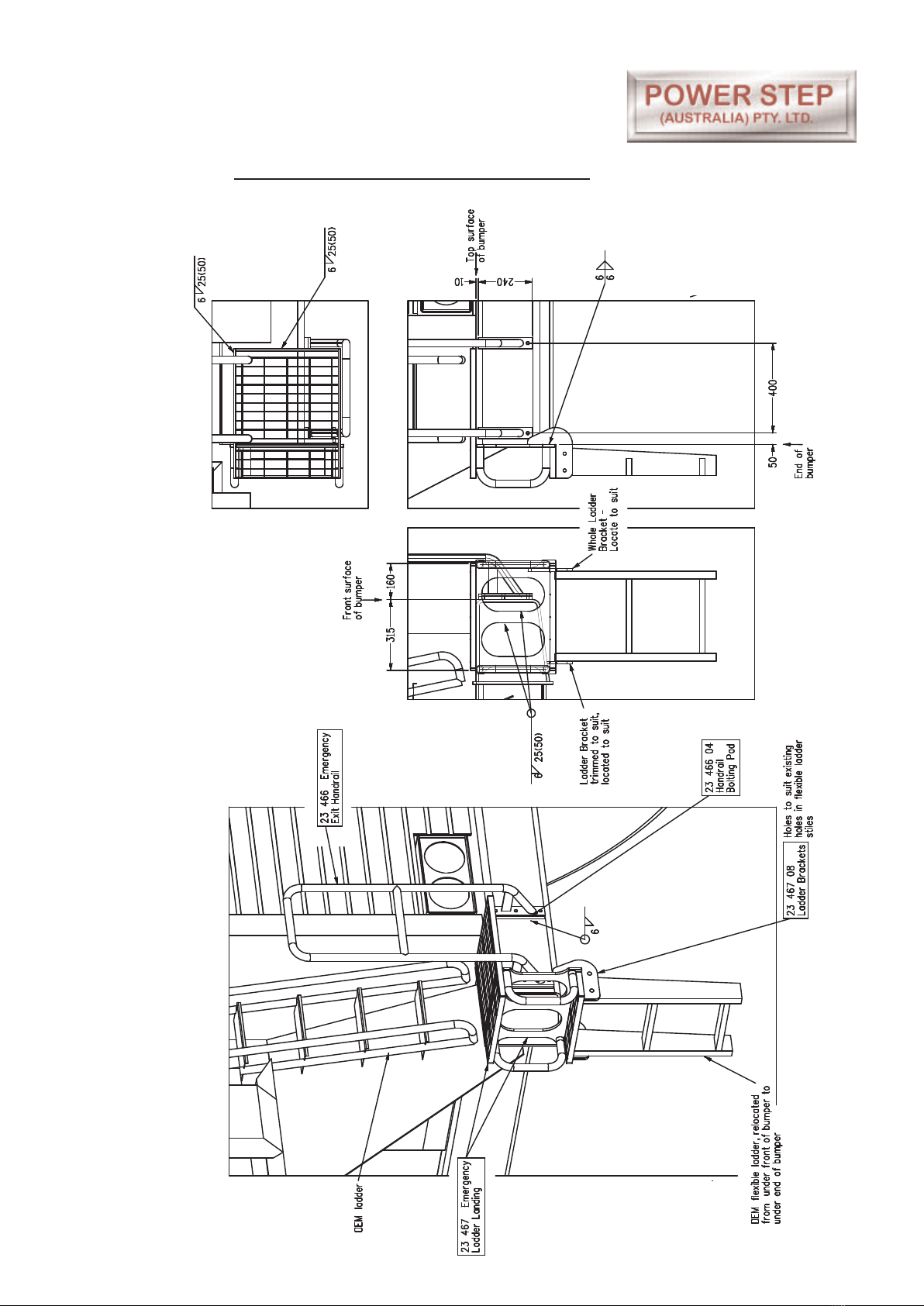
Power Step Cat 789C User manual

PSA789C-ASSY 12-3-10
Operations and Maintenance Manual
Cat 789C
Folding Stair Assembly
Model No. PSA789C-FS
Serial No. 789C-FS004
Date Manufactured: June 09

FOLDING STAIRWAY
Caterpillar 789C Haul Truck
Pg2
PSA789C-ASSY 12-3-10
CONTENTS
Page 3Section 1. Installation and Mounting Instructions
Drawings and procedures
9Section 2. Electrical Installation
12 Section 3. Installation of Hydraulic Lines & Cylinder
14 Section 4. Operating Procedure
15 Section 5. Recommended Maintaintence Procedure
Section 6. Drawings and Repair Parts Lists
16 6 Stair Assembly Complete
17 6-1 Top Stair & landing Assembly
Parts List
19 6-2 Middle Stair Assembly
Parts List
21 6-3 Lower Stair Assembly
Parts List
23 6-4 Emergency Ladder Assembly
Parts List
24 6-5 Hydraulic Cylinder
Parts List
26 6-6 Power Pack
Parts List
28 6-7 Electrical System/Controls
Parts List

FOLDING STAIRWAY
Caterpillar 789C Haul Truck
Section 1. Installation and Mounting Instructions Bolting Pads 23 471
Pg3
PSA789C-ASSY 12-3-10
NOTE
Follow all on-site/Mine lifting and safety procedures when installing
Power Step Ladder System to the Truck
PROCEDURE
See Drawing 23471 Pg. 4.
1. Remove the OEM steel ladder (above the bumper), the bumper-top landing plate
and the flexible below-bumper ladder from the left side of the truck. Remove just
the landing plate and flexible ladder from the left side, leaving the above-bumper
ladder.
2. Locate Bolting Pads 23 468 01 on the front of the bumper as shown in View 1.1
with dimensions per View 2.1 Locate 23 458 04 Bolting Plate on the end of the
bumper. Underlined dimensions (down from cabin landing) rule if there is a
discrepancy between imensions measured down from radiator surround vs dims
from cabin floor. Weld Pads/Plates to bumper per details in Views 2.1, 2.2 & 2.3.
Attach gussets also.
3. Fit 23 459 98 Isolator Mounting as shown in Views 1.1 & 1.2. Location per
dimensions View 2.1

Pg4
PSA789C-ASSY 12-3-10
FOLDING STAIRWAY
Caterpillar 789C Haul Truck
Section 1. Installation Instruction Drawings Bolting Pads
VIEW 4.1
VIEW 1.2
VIEW 2.2 VIEW 2.3
VIEW 3.1
VIEW 1.1
Drawing 23471

FOLDING STAIRWAY
Caterpillar 789C Haul Truck
Section 1. Installation and Mounting Instructions - Stair Set
Pg5
PSA789C-ASSY 12-3-10
PROCEDURE
Refer Drawing 23473 Pg. 6
1. Middle and Top part of stair to be bolted and lifted together but without the top
landing floor panel fitted to the top stair.
Combined assembly is bolted to pads on front of bumper.
Note lifting points for slinging (Painted Red with lift stickers.)
See Views 2 and 3.
2. Fit Mounting Tie 23 459 99 per View 4.
3. Fit top landing floor panel to top of top stair. Trim if necessary. Adjust height to be
level with OEM cabin landing floor.
4. Fit Buffer Socket & Mounting 22 242 (with gusset) in suitable position to receive
Buffer when Stair is raised. Pad 22 242 01 welds to truck bumper behind hinged
stair. First bolt Socket Bracket 22 242 99 to Pad 22 242 01 with bolts in slots so
Bracket is as high as possible relative to Pad. Fit & weld to bumper so Socket sits
on Buffer. Adjust so stair is tight in raised position, not swinging with truck
movement.
Assembled Stair

Pg6
FOLDING STAIRWAY
Caterpillar 789C Haul Truck
Section 1. Installation Instruction Drawings Stair Set
PSA789C-ASSY 12-3-10
VIEW 3
VIEW 2
VIEW 6.1 VIEW 6.2
VIEW 4
Drawing 23473

FOLDING STAIRWAY
Caterpillar 789C Haul Truck
Section 1. Installation Instruction Drawings - Emergency Exit
Pg7
PSA789C-ASSY 12-3-10
PROCEDURE
See Drawing Pg 23474 Pg. 8.
1. Shorten OEM Ladder as required -View 2.2 so that Emergemcy laddder will fit.
2. Weld the Emergency Ladder Landing to the bumper as shown in View 1. Location
and weld details per Views 2.1, 2.2 & 2.3
3. Weld the bolting pads for the Emergency Exit Hand-rail to the front of the bumper,
arrangement and weld details per View 1, location per Views 2.2 & 2.3. Bolt
Handrail to bolting pads.
4. Weld Ladder Brackets to main plate of Emergency Ladder Landing and to bumper
(inner bracket trimmed to suit) in a location to suit the width of the OEM flexible
ladder. Drill holes in brackets to suit holes in flexible ladder and attach ladder to
Brackets.

FOLDING STAIRWAY
Caterpillar 789C Haul Truck
Section 1. Installation Instruction Drawings Emergency Exit 23 474
Pg8
PSA789C-ASSY 12-3-10
VIEW 2.3
VIEW 2.2
VIEW 2.1
VIEW 1

FOLDING STAIRWAY
Caterpillar 789C Haul Truck
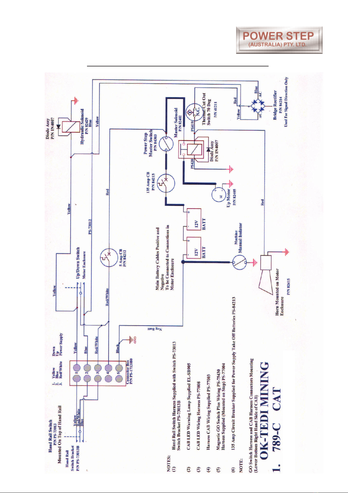
Section 2. Electrical Installation (Cabin & Wiring harnesses)
Refer also to Wiring Diagrams Electrical
Pg9
PSA789C-ASSY 12-3-10
PROCEDURE
Fit Step up/down Warning Beacon in suitable position. (In Cab) as per Photo.
Remove four (4) screws holding Caterpillar fuse panel behind operator's seat. Drill one
hole to insert Caterpillar fuse holder - fit fuse holder, into fuse indicator panel - tighten.
Drill size (12mm or 15/32").
Remove rear access panel from back of cabin and run short conduit through the main
cable gland to inside centre console, ensuring conduit goes underneath control box.
Connect blue wire start from conduit above to blue wire of cabin indicator panel harness.
In rear access, connect black wire, with 10mm eye terminal to machine ground, and blue
wire to outer terminal of newly inserted fuse holder.
Install short blue wire to screw terminal of Caterpillar circuit breaker, and other end to fuse
holder.
Run wiring harness from Power Step Stairway magnetic proximity switch and follow
cabling/hose routing up to air line/ electrical outlet on rear Right Hand Side of cabin.
Drill hole in RH Cabin access panel - route wiring harness in through access panel, and
through to under centre console - connect wires appropriately as colour coded. Hole saw/
drill size (24mm), cable tie harness as appropriate, approximately every 300mm.

FOLDING STAIRWAY
Caterpillar 789C Haul Truck
Section 2 . Electrical System - Wiring Diagram - Harnesses
Pg10
PSA789C-ASSY 12-3-10

FOLDING STAIRWAY
Caterpillar 789C Haul Truck
Section 2. Electrical System - Wiring Harness
Pg11
PSA789C-ASSY 12-3-10

FOLDING STAIRWAY
Caterpillar 789C Haul Truck
Section 3. Installation of Hydraulic Lines and Cylinder
See Drawing Page 13
Pg12
PSA789C-ASSY 12-3-10
NOTES
(Fitment Hinge and Actuator Assembly)
1. The stair hinge is not to be loaded by extending cylinder force, that is the cylinder
must be able to extend to it’s full extention length without being restained by the
assembly. If this is not so when the stair is assembled, loosen the various hinge
assembly bolts and actuator attachment plate bolts and extend the cylinder under
load, allowing everything to re-set. If the cylinder is still loaded alter boltholes etc to
allow appropriate re-positioning.
2. Use hardened flat washers under the heads and nuts of all bolts as supplied.
3. Run Hydraulic Hoses to motor enclosure using clamps supplied
4. Note: The Cylinder and Power Pack have been connected in the workshop and
cycled prior to delivery.

FOLDING STAIRWAY
Caterpillar 789C Haul Truck
Section 3. Installation of Hydraulic Lines and Cylinder
See Pg. 26 Hydraulics Diagram
Pg13
PSA789C-ASSY 12-3-10
See hinge assembly details
CYLINDER HINGE AND ACTUATOR ASSEMBLY
HINGE ASSEMBLYDETAILS
(Refer Parts list on Pg. 24)

FOLDING STAIRWAY
Caterpillar 789C Haul Truck
Section 4. Operating Procedure
Pg14
PSA789C-ASSY 12-3-10
To Lower Stairway (from the machine)
Position machine in a level, safe area, away from the work face, whenever possible.
Apply park brake and lower engine speed to idle.
Check that the area below the Stair Access System is clear of people and
obstacles, and lower Stair by operating the two position electrical switch adjacent
to the stair, to the down position by pressing the switch down.
Hold the switch in the down position until Stair is fully lowered.
If the truck is parked on uneven ground, the bottom of the stairway may touch the
ground before the ladder is in the fully lowered position.
Should this occur, descend the Stair with caution.
To Raise Stairway
Ascend the Stair onto the landing of the truck.
Ensure the area around the Stair is clear of people and standing to the side, clear
of the area the handrails and Stair raises into, operate the electrical switch to the
raise position (up).
Hold the switch in the up position until the Stair is in the fully raised position.
The Stair is now raised and stored.

FOLDING STAIRWAY
Caterpillar 789C Haul Truck
Section 5. Recommended Maintenance Procedure
Pg15
PSA789C-ASSY 12-3-10
Daily
Visually check stairway and structure for damage, loose components,
handrails, etc.
Check for hydraulic oil leaks from hydraulic cylinders, plumbing and hoses.
Notify the appropriate supervisor for any observed damage or malfunction.
500 Hours
Grease 4 grease nipples on pivot & cylinder pins accessible with the stairway
lowered.
Check main mounting bolts for torque.
Check hydraulic oil level in power pack and top up as necessary. (Stairway in raised
position).
Top up using same hydraulic oil as used in hydraulics of machine.
Thoroughly check all electrical wiring for damage, replace as necessary.
Repeat daily check as above
5000 Hours
Change hydraulic oil in tank of hydraulic power pack (5.0 litres)
It is recommended that the same hydraulic oil be used in the power pack as the
hydraulics of the machine.
Grease 4 grease nipples on pivot & cylinder pins accessible with the stairway
lowered, and accessed from under the stairway.
Check and inspect all main bolts on stairway system.
Retorque if required.
Repeat daily check as above

Pg16
FOLDING STAIRWAY
Caterpillar 789C Haul Truck
Section 6. Assembly Complete PSA-789C-FS
PSA789C-ASSY 12-3-10

FOLDING STAIRWAY
Caterpillar 789C Haul Truck
Section 6-1. Top Stair & Landing Assembly PS-23456-A
Pg17
PSA789C-ASSY 12-3-10

FOLDING STAIRWAY
Caterpillar 789C Haul Truck
Section 6-1. Top Stair & Landing Assembly PS-23456-A
See Pg 17
Pg18
PSA789C-ASSY 12-3-10
Item Part No. Part Name Qty
1
2
3
4
5
6
7
8
9
10
11
12
13
14
15
16
17
18
PS-23456
PS-22457
PS-22266-A
PS-23461-A
PS-23463
PS-23458
PS-23459-98
PS-23459-99
PS-21930A
PS-M20X40ZP
CPS-M12X100ZP
CPS-M12X35ZP
CPS-M12X30ZP
CPS-M12X25ZP
CPS-M12ZP
CPS-M20WH
CPS-M25WH
PS-32266-SAN
TOP STAIR FABRICATION
TOP LANDING EXTENSION
STAIR TREADS
HANDRAIL-TOP-OUTER
HANDRAIL-TOP-INNER
LANDING POST FRAME
ISOLATOR MOUNTING
TIE
ISOLATOR & BRACKET
BOLT-M20 x 40
BOLT-M12 x 100
BOLT-M12 x 35
BOLT-M12 x 30
BOLT-M12 x 25
NUT-M12
WASHER-HARDENED-M20
WASHER-HARDENED-M12
NON SLIP NOSING
1
1
3
1
1
1
1
1
1
4
1
6
38
8
45
4
100
5

FOLDING STAIRWAY
Caterpillar 789C Haul Truck
Section 6-2. Middle Stair Assembly PS-23453-A
Pg19
PSA789C-ASSY 12-3-10

FOLDING STAIRWAY
Caterpillar 789C Haul Truck
Section 6-2. Middle Stair Assembly PS-23453-A
See Pg 19
Pg20
PSA789C-ASSY 12-3-10
Item Part No. Part Name Qty
1
2
3
4
5
6
7
8
9
10
11
12
13
14
15
16
17
18
19
20
21
22
23
24
25
26
27
28
29
30
31
32
33
34
PS-23453
PS-23462-A
PS-23460
PS-22266
PS-23452-99-A
PS-23452-98-A
PS-22233-05-C
PS-21107METAL
PS-63009B
PS-22238
PS-23452-07-A
PS-22246
PS-22246-05
PS-22246-04
PS61006-2
PS-75430
PS-M24X65ZP
CPS-M16X30ZP
CPS-M12X50ZP
CPS-M12X35ZP
CPS-M12X30ZP
CPS-M12X25ZP
CPS-M8X50ZPSH
CPS-BSW3/16”X2
CPS-M12NZP
CPS-M8NL
CPS-BSW3/16”NUT
CPS-M24WH
CPS-M16WH
CPS-M12WH
CPS-WS/SPRING
CPS-WS/S3/16”X1/2”
CPS-WS/S3/16”X3/4”
PS-32266-SAN
STAIR STILE FABRICATION
HANDRAIL-OUTER- RH
HANDRAIL-INNER - LH
STAIR TREADS
LEFT SIDE MOUNTING
RIGHT SIDE MOUNTING
FIXED STAIR ACTUATOR ATTACHMENT
POWER PACK ENCLOSURE
CYL-MOUNTING-BUSH
GO SWITCH MOUNTING BRACKET
BRACKETS-POWER PACK ENCLOSURE
HINGE PIN
BUSH
SPACER-THIN
GREASE NIPPLE M6 STR.
GO SWITCH
BOLT-M24 x 65
BOLT-M16 x 30
BOLT-M12 x 50
BOLT-M12 x 35
BOLT-M12 x 30
BOLT-M12 x 25
BOLT-M8 x 50 Socket/Hd
BOLT - (Go Switch)
NUT-M12
NUT-M8-NYLOC
NUT-3/16”S/S NUT
WASHER-HARDENED-M24
WASHER-HARDENED-M16
WASHER-HARDENED-M12
WASHER-SPRING-3/16”
FLAT WASHER
FLAT WASHER
NON SLIP NOSING
1
1
1
5
1
1
1
1
1
1
2
2
2
2
2
1
8
12
12
2
36
4
2
2
52
2
2
8
12
52
2
2
2
5
Table of contents
Other Power Step Tractor Accessories manuals
Popular Tractor Accessories manuals by other brands

Kubota
Kubota VC5045A owner's manual

Craftsman
Craftsman CMXGZBF7124441 instruction manual

BE Ag & Industrial
BE Ag & Industrial BACKHOE BE-BK Series Operations & parts manual

Sulky
Sulky XT160H Original instructions

TigerTough
TigerTough E82219 quick start guide

Avantco
Avantco A37456 Operator's manual for Attachment