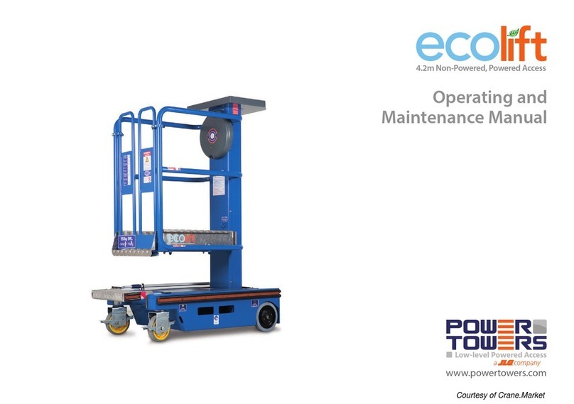
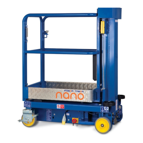
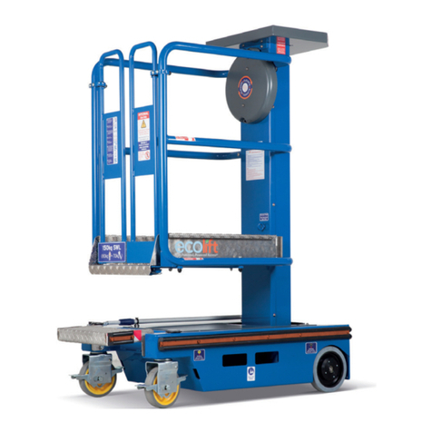
Power Towers pecolift Operating instructions

Operating and
Maintenance Manual
by

CONTENTS
Introduction 2
Operating specifications 3
Working envelope diagram 3
Do’s and Don’ts 4
Primary components 5
Operating procedures (incl. emergency operation) 6-8
Maintenance procedures 9-10
Storage 11
Key spare parts 12
Warranty terms 13
CONTENTS
2
INTRODUCTION
The Power Tower Pecolift is a simple, safe and efficient alternative
to step-ladders,platform/podium steps and small scaffold towers.
Pecolift is the first non-powered, powered access platform. It does not
require batteries (or charging) or connection to an electricity supply. It
works by a unique, patented stored power mechanism which enables
the platform to be elevated with very little effort by the operator.
Pecolift is designed for working internally on flat, level surfaces,
and as it has no batteries, electric motor, electrics or hydraulics it is
very ecologically friendly. It is ideally suited to working in a very wide
range of applications from the very ‘clean’ environments of
hospitals, food and drinks production facilities, pharmaceuticals and
retail, to facilities maintenance, shop-fitting and construction.
The Pecolift is suitable for any application provided it is used within
its specified operating parameters. If used for applications such as
sand blasting, welding, paint spraying or with any other hazardous
materials, measures must be taken to ensure the Pecolift does not
become damaged in any way which may impair safety, or reliability.
Additional protection for the operator may be required in some cases,
which is the responsibility of the operator and/or the operator’s
employer.
The purpose of this manual is to provide essential basic information
required to operate and maintain the Pecolift.

OPERATING SPECIFICATIONS
Working Dimensions
Maximum working height: 3.50 m
Maximum platform height: 1.50 m
Platform dimensions: 720 mm (L) x 600 mm (W)
Working footprint: 985 mm x 700 mm
Safe working load: 150 kg (1 person + tools)
Maximum manual force: 200 N
Maximum gradient for operation: 0 degrees
Maximum wind force: Internal use only, 0 (zero) mph
Maximum wheel force: 125 kg
Maximum castor point load: 125 kg (123kN)
Sound pressure level: Less than 70Dba
Closed Dimensions
Length: 985 mm
Width: 700 mm
Height: 1.550 m
Weight: 155 kg
Lift Cycles Unlimited, subject to maintenance
program being adhered to.
OPERATING SPECIFICATIONS
3

DO’S and DON’TS
4
DO’S
1. Read and adhere to the instructions both on the machine and in
the Instruction Guide or Operating Manual.
2. Ensure pre-operation checks & operations are carried out in the
manner described.
3. Use only on hard, level surfaces able to support the weight
of the machine.
4. Use the Pecolift internally only.
5. Ensure the operator is t and does not suer from a
fear of heights.
6. Ensure guardrail gates are closed before elevation.
7. Ensure work area around the machine is cordoned o from
pedestrians and other trac.
8. Ensure operator is wearing the correct safety equipment.
9. Ensure the platform is correctly positioned so as not to come into
contact with xed or moving objects.
10. Ensure that the safe working load is evenly distributed
on the platform.
11. Ensure the machine is being operated within the PUWER
(Provision and Use of Workplace Equipment Regulations).
DON’TS
1. Never exceed the safe working load (1 person plus tools, 150kg).
2. Never use the Pecolift as a goods lift or crane.
3. Never exceed horizontal forces, (maximum horizontal force 200N).
4. Never use in the vicinity of live conductors.
5. Never try to move the Pecolift on its wheels when elevated.
6. Never extend the height of the platform by using boxes,
steps, ladders etc.
7. Never modify the Pecolift in any way without the full written
approval of the manufacturer.
8. Never attempt to enter or exit the platform unless it is
fully lowered.
9. Never use the Pecolift on sloping or uneven ground.
10. Never operate the Pecolift outdoors, or anywhere it may be
aected by wind.

PRIMARY COMPONENTS
PRIMARY COMPONENT LOCATIONS
5
Flywheel
Spirit
Level
Swivel
Castor
Auto-Lok
Braked Wheel
Emergency
Lowering Tool
Tool Tray
Rubber Foot (Pad)
Gates
Platform
Tray
Flywheel
Handle

OPERATING PROCEDURES
It is essential to be familiar with the correct operating procedures.
The operator must have adequate training for this type of platform.
The Pecolift can be fitted with a safety harness point. If the operator
chooses to wear a safety harness, an approved‘fall restraint’ type harness
should be worn with a very short lanyard.
Operating procedures are divided into three key areas:
1. Pre-operation checks.
What to do before operating the Pecolift.
2. Normal operation.
How to use the Pecolift safely.
3. Emergency operation.
How to lower the Pecolift in the event of operator incapacity.
6

PRE-OPERATION CHECKS
1. Visually inspect the Pecolift for any signs of damage to handrails, platform tray,
chassis and mast lifting structure including mast fixing bolts.
2. Check castor and wheels rotate freely and are undamaged.
3. Check castor (pic 1) and wheel fixings (pic 2) are secure.
4. Check that the front rubber chassis feet (pads) are undamaged
and fixings are secure (pic 3).
5. Check spirit level (pic 4) is intact and bubble is centred to ensure machine is level.
6. Check gates,gate hinges, hinge springs and hinge fixings are undamaged and
that gates open and close correctly (pic 5).
7. Step into basket; check machine sinks down to rest on front
rubber pads (feet) (pic 3a).
8. When standing in the basket: check ‘fly-wheel’operating handle works correctly.
Hold handle firmly and pull operating knob towards you, release,knob should
spring back to lock wheel. Repeat but turn handle once clockwise with
knob held pulled towards you.Wheel should turn freely.Turn once
anti-clockwise to come down (pic 6).
9. Check emergency lowering tool is attached on the chassis.
NORMAL OPERATION
Only use the Pecolift internally, on hard level surfaces. Ensure a person
is available at ground level to assist in case of emergency.
1. Position machine under application.
2. Check spirit level to ensure machine is level.
3. Step into platform through gates, ensure gates close behind you
and check machine is sitting on its rubber pads (feet);
DO NOT ELEVATE IF NOT.
4. Check there are no overhead obstructions.
5. To elevate: pull operating knob towards you and turn clockwise.
To stop, stop turning the handle and release handle knob to lock.
6. To descend repeat but turn handle anti-clockwise.
OPERATING PROCEDURES
7
12
3 4
55
6
The user shall obtain the guidance and approval of the
manufacturer in the event of any special working methods or
conditions outside those specified by the manufacturer.
3a

EMERGENCY LOWERING OPERATION
Never attempt to recover the machine/operator if there is any
possibility the machine is contacting any live wiring/cabling and
is therefore potentially ‘live’.
To lower the platform in the event of the operator being
incapacitated (unable to operate the flywheel handle in the
basket):
1. Locate emergency lowering tool on chassis (pic 2),
remove from fixing.
2. Stand to side of machine, attach‘hook’ end of emergency
lowering tool to fly-wheel handle knob in basket, releasing
handle knob, turn wheel anti-clockwise to bring platform down
(pic 1).
3. Keep clear of structure as it descends.
4. Lower to a platform height of approximately 500mm or less
to recover the operator safely.
OPERATING PROCEDURES
8
Emergency lowering tool located on chassis
Turn wheel anti-clockwise to bring platform down
1
2

Please note that whilst the Pecolift is extremely simple to
maintain, all work must be carried out by a competent person.
DAILY MAINTENANCE
Note: The telescopic mast is a sealed unit which contains a
pressurised cylinder and can only be dismantled by a trained person
authorised by the manufacturer.
The most important regular maintenance to be carried out by the
operator is visual inspection, as per the pre-operation checks.
Daily Checks
The safety critical items to inspect each work session, daily as a
minimum are:
1. Check there is no damage to the following: wheels and rubber
pads (feet) and check that their fixings are secure. These are the
components that connect the machine to the ground; if they are
damaged then operating the machine could be dangerous and
and may result in serious injury.
2. Check that the guard rails are not damaged and all fixings are
secure.
3. Check gates, gate hinges, hinge springs and fixings are secure and
gates close freely. Ensure gates cannot open outwards.
4. Check chassis is not damaged and spirit level is intact and working.
5. Check mast fixings are all present and secure.
6. Check castor mounting allows machine to sink onto its rubber
pads (feet) when stepping on front of platform. Check
machine‘springs’ back up again when weight is removed from
platform and machine is pushed forward.
7. Check fly-wheel handle operates correctly: step into the platform
to do this: (do not attempt to operate the handle from outside
the basket).Pull flywheel handle knob towards you, release.
Ensure handle springs back to lock wheel.Turn wheel one
revolution clockwise then anti-clockwise; ensure handle
moves freely in either direction.
8. Check automatic wheel-brake works by: repeat no. 7; when
platform is elevated approximately 100mm,step out of the
platform and attempt to push the machine, machine should not
move, wheels should be braked.
9. Check emergency lowering tool is attached to chassis and not
damaged.
Monthly Checks
As daily checks (items 1-9).
MAINTENANCE PROCEDURES
9
NOTE: PUWER (The Provision and Use of Workplace Equipment
Regulations 1998) stipulates that suppliers such as hire
companies must ensure their equipment is maintained
correctly and fully serviced. Once on site, it is the hirer/
employer’s responsibility to ensure the machine remains in
serviceable condition. The hirer/employer must also ensure the
operator is properly trained and familiarised with the machine
in order to operate it correctly.

MAINTENANCE PROCEDURES
Six Monthly Checks - LOLER
1. Remove handle cover using suitable security screw tool
and inspect and lubricate gearwheels. Use Omega 73 no. 2 harsh
environment grease or equivalent. Do not use standard gear
grease because it will dry out prematurely and will lead to
premature gear wear. Paint seal screws when refitted.
2. Inspect the drive belt for signs of wear. In order to do this,
remove handle cover as in 1). Stand in the platform and raise
and lower the platform in the normal manner described in
the operating procedures.Whilst the platform is being raised
and lowered, the belt and teeth can be observed through the
inspection panel under the handle cover. Minor scuffing and wear
is acceptable, but there should be no signs of the inner braided
wire or Kevlar cords visible. Paint seal screws when refitted. If
there are any signs of excessive wear, contact the manufacturer or
authorised distributor.
3. The machine should be subjected to the test procedure below.
Note,the dynamic test requirement is achieved by an excess static
load test (190%) which replicates the loads seen during dynamic
movement with 125% SWL due to the necessity to achieve a safe
method of conducting the test.
4. Check the mast interlock is undamaged. Check the casing for signs
of damage and remove the end plate. Check the plunger
is free to move by holding end with long nosed pliers and pulling
outward and then releasing.Ensure plunger springs back freely.
Refit cover and screw. Paint seal screw when refitted.
5. Inspect condition of automatic wheel lock.Look under brush
strip at rear of chassis when platform is elevated so that mast outer
is clear of chassis. Check brake cam plates are undamaged and
that the two attaching screws are tight.With an assistant to lower
the platform, observe the action of the cams and the movement
of the brake pins. Ensure the movement is free and the pins clear
the wheel discs.When the platform is elevated ensure the pins fully
engage the brake discs. Ensure the pockets in the wheels are in
good condition.
6. Check all instruction labels are present and clear. Refer to the key
spare parts.
When replacing components for any reason, only use OEM specification
parts, either supplied from the manufacturer or authorised in writing
by the manufacturer.Warranties and design approvals will be void if
alternative components are fitted.
It is essential to obtain manufacturer’s approval of any alteration
which might affect stability, strength or performance in writing before
proceeding.
When refitting a rear wheel always use a new cotter pin (4mm
diameter x 32mm A2 stainless steel). NEVER REFIT A USED
COTTER PIN.
10
Test Procedure
Place machine on test pad.
Dynamic Test EN280 2001 (E) 6.1.4.3
Place 190% SWL (285kg) in platform
when elevated 100mm from rest.
Function Test to full height EN280 2001
(E) 6.1.4.4 with 110% SWL = 165kg.
Whilst lowering release control handle and
ensure lowering stops immediately.
Fail Pass

11
STORAGE
If the machine is due to be stored for periods in excess of one month,
the following precautions should be taken: ensure the machine is
fully lowered and ideally place a cover over the machine.
Upon removal from storage and prior to returning to use, ensure
machine pre-operation checks are carried out thoroughly, check
LOLER certificate is current.
STORAGE OF Pecolift

Part No.
A Wheel/Brake Sprocket PEL-M-400
B Swivel Castor PEL-M-401
C Spirit Level PT-M-106
D Peco-lift gates (pair) PEL-M-402
E Corner Foot (Pad) PEL-M-403
F Mudguard PEL-M-404
G Tool Box PEL-M-405
H Peco-lift Decal Set 1 PEL-M-600
I Peco-lift Decal Set 2 PEL-M-601
J Peco-lift Decal Set 3 PEL-M-602
K Chassis Cover PEL-M-406
L Emergency Lowering Tool PEL-M-407
M Flywheel PEL-M-408
N Platform Tray PEL-M-800
O Front Cone Rubber Buffer PEL-M-409
12
KEY SPARE PARTS
A B C
D E F
G H JI
K L M N O

WARRANTY TERMS
Your Pecolift is covered by an 18 month parts/components warranty.
The Manufacturer Power Towers Ltd (The Company), undertakes to replace
or repair, free of charge, any defective part/component, which the Company
considers to be due to faulty workmanship or material within 18 months of
the sale date,except for:
The telescopic mast is a sealed unit. If the mast is opened in any way
warranty may be invalid.
Defects arising from neglect, misuse or unauthorised modifications.
Damage caused by abuse,misuse, dropping or other similar damage caused
by or as a result of failure to follow transportation, storage, installation, loading
or operation instructions.
Alterations, additions or repairs carried out by persons other than the
Manufacturer or their recognised distributors.
Transportation or shipment costs to and from the Manufacturer or their
recognised agents,for repair or assessment against a warranty claim, on any
Pecolift or component.
Materials and/or labour costs to renew, repair or replace components due to
fair wear and tear.
Faults arising from the use of non-standard or additional parts, or any
consequential damage or wear caused by the fitting or use of such parts.
Important
Warranty may, at the sole discretion of the Manufacturer, be voided if the
scheduled service/inspections are not carried out in accordance with this
manual.
The Manufacturer and/or their recognised agents, directors, employees or
insurers will not be held liable for consequential or other damages, losses or
expenses in connection with or by reason of or the inability to use the Pecolift
for any purpose.
Modifications
If additional equipment or any third party work, modifications or alterations
are to be carried out on the Pecolift which will involve any welding, drilling
or any form of cutting or distortion of materials, full written approval must be
obtained from the Manufacturer prior to the work being carried out.
13
WARRANTY

TEST RESULTS & NOTES
Description Work Carried out Date
ALTERATIONS & REPAIRS
Description Work Carried out Date

PECO-OP | UK | 01.13
www.powertowers.com 100% British designed and manufactured.
Other manuals for pecolift
1
Table of contents
Other Power Towers Lifting System manuals
Popular Lifting System manuals by other brands

Oshkosh Corporation
Oshkosh Corporation JLG 260MRT Service maintenance manual

RUD
RUD Ice 120 User instructions

Peak
Peak SML-6 Installation and service manual

Faraone
Faraone ELEVAH 40 MOVE PICKING Use and maintenance instructions

AUTOCHAIR
AUTOCHAIR SmartLifter LP Series User & installation manual

Genie
Genie gS-1530/32 Operator's manual