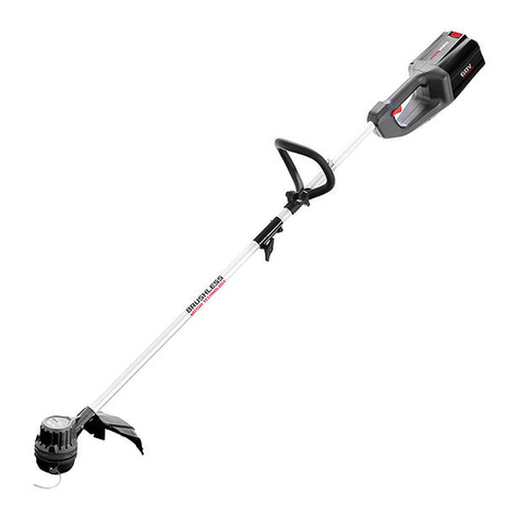
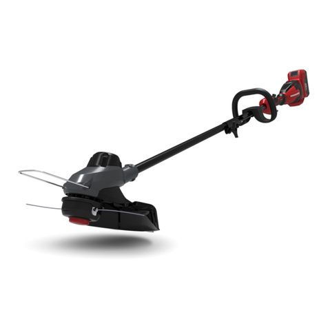
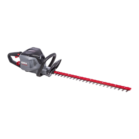
Power works PD60BCB User manual

2102913
PD60BCB
60V battery lawn trimmer an d brush cutter 2 in 1 USER’S MANUAL
60V akku 2 in 1 rasentrim mer und freischneider BEDIENUNGSANLEITUNG
Batería de 60V de la desbrozado ra y cortasetos 2 en 1 MANUAL DE UTILIZACIÓN
Bordatore e decespugliatore 2 in 1 da 60V a batterie MANUALE D’USO
Tondeuse et débroussailleus e 2-en-1 alimentée par batterie 60V MANUEL D’UTILISATION
Aparador de relva e máquina de corta -mato 2 em 1 com bateria de 60V MANUAL DE UTILIZAÇÃO
2-in-1: 60V batterijaangedrev en grastrimmer en struikruimer GEBRUIKERSHANDLEIDING
60V akkukäyttöinen ruohotrimmeri ja pensasleikkuri 2-in-1 KÄYTTÄJÄN KÄSIKIRJA
60V batteridriven grästrimmer och röjsåg, 2-i-1 INSTRUKTIONSBOK
60V batteri til plen- og krattkli pper - 2 i 1 BRUKSANVISNING
60V batteridrevet plæneklipper o g kratrydder 2 i 1
Akumulatorowa podkaszarka do trawy i wykaszarka 60V 2 w 1
60V akumulátorová sekacka trávy a krovinorez 2 v 1
60V akumulátorový strihac trávnika a krovinorez typu 2 v 1
60-voltna baterijska kosilnica in obrezovalnik 2-v-1
60V akkumulátoros fuszegélynyíró és bozótvágó 2 az 1-ben
Aparat de tuns gazonul si de tuns gardul viu 2 în 1 la 60V
"Kaks-ühes" murutrimmer akuga 60 V ja võsalõikur
1
7
13
18
1
24
29
34
39
45
50
55
60
65
70
75
80
85
90
95
100
106
112
117
122
127
132
137
DE
ES
IT
FR
PT
NL
RU
FI
SV
NO
DA
PL
CS
SK
SL
HR
HU
RO
BG
EL
AR
TR
HE
LT
LV
ET
EN
BRUGERVEJLEDNING
NÁVOD K OBSLUZE
KORISNIÈKI PRIRUÈNIK
HASZNÁLATI ÚTMUTATÓ
MANUAL DE UTILIZARE
KULLANICI KILAVUZU
KULLANICI KILAVUZU
NAUDOJIMO VADOVAS
KASUTUSJUHEND

English (original instructions)
EN
DE ES IT FR PT NL RU FI SV NO DA PL CS SK SL HR HU RO BG EL AR TR HE LT LV ET
SPECIFICATIONS
Voltage 60 volts
No load speed 6500 ( ±10% /min
Cutting head Bump feed/Brush-cutter Blade
Cutting Line
Diameter
2.0 mm
Cutting Path
Diameter
356/406 mm (Lawn trimmer)
254 mm (Brush cutter)
Battery pack 2900413/2900913/2900513/290461
3/2904713
Charger 2900313/2904813
Weight with
battery pack
6.6 kg
Lawn Trimmer Measuered sound
pressure level
Measuered sound
power level
91.91 dB(A)
Guaranteed
sound power level
96 dB(A)
Vibration <2.5m/s2
k=1.5m/s2
Brush Cutter
Measuered sound
pressure level
Measuered sound
power level
91.1 dB(A)
Guaranteed
sound power level
96 dB(A)
Vibration <2.5m/s2
k=1.5m/s2
WARNING
The vibration emission during actual use of the power
tool can differ from the declared total value depending
on the ways in which the tool is used; avoid vibration risk
time and shorten trigger time.
DESCRIPTION
1. Switch trigger
2. Rear handle
3. Lock-out trigger
4. Front handle
5. Shaft
6.
7. Cut-off blade
8. Blade
ASSEMBLY
UNPACKING
This product requires assembly.
Carefully remove the product and any accessories
from the box. Make sure that all items listed in the
packing list are included.
WARNING
Do not use this product if any parts on the Packing List
are already assembled to your product when you un-
pack it. Parts on this list are not assembled to the prod-
uct by the manufacturer and require customer installa-
tion. Use of a product that may have been improperly
assembled could result in serious personal injury.
Inspect the product carefully to make sure no breakage
or damage occurred during shipping.
Do not discard the packing material until you have
carefully inspected and satisfactorily operated the
product.
WARNING
If any parts are damaged or missing do not operate this
product until the parts are replaced. Use of this product
with damaged or missing parts could result in serious
personal injury.
WARNING
Do not attempt to modify this product or create acces-
sories not recommended for use with this product. Any
-
sult in a hazardous condition leading to possible serious
personal injury.
1

English (original instructions)
EN
DE ES IT FR PT NL RU FI SV NO DA PL CS SK SL HR HU RO BG EL AR TR HE LT LV ET
WARNING
To prevent accidental starting that could cause serious
personal injury, always remove the battery pack from the
product when assembling parts.
ATTACHING GRASS DEFLECTOR See Figure 2.
WARNING
Avoid contact with the blade. Failure to avoid contact
can result in serious personal injury.
Invert the string trimmer to access the trimmer head.
Using a Phillips head screwdriver, remove the
preinstalled screws (a) from the trimmer head.
Place the guard (b) on to the trimmer head and slide
the guard onto the head by following the track on the
head.
Align the screw holes on the guard with the screw holes
on the trimmer head.
Insert the screws into the trimmer head, fastening the
guard in place.
Place the guard cap (c) on to the guard and slide the
guard cap onto the guard.
Align the screw holes on the guard cap with the screw
holes on the guard.
Insert the screws into the guard, fastening the the
guard cap in place.
WARNING
Do not allow familiarity with products to make you care-
less. Remember that a careless fraction of a second is
WARNING
Always wear eye protection. Failure to do so could result
in objects being thrown into your eyes resulting in pos-
sible serious injury.
WARNING
Do not use any attachments or accessories not recom-
mended by the manufacturer of this product. The use
of attachments or accessories not recommended can
result in serious personal injury.
ATTACHING THE FRONT HANDLE See Figure 3.
Unscrew the central knob 'A', remove the cap 'B' and
the lower support 'C', being careful not to lose the
spring in the support.
Place the handle in the lower support.
Hook the cap 'B' to the lower support 'C' and place the
entire block in its housing on the transmission shaft.
Set the handle bar in the most comfortable working
position and lock it using knob 'A'.
OPERATION
Hold the power head with your right hand on the rear han-
with both hands while in operation. Power head should be
held at a comfortable position with the rear handle about
hip height. Always operate power head at full throttle. If de-
bris becomes wrapped around the attachment, RELEASE
THE SWITCH TRIGGER, and remove the debris.
Use the harness when operation.
TO INSTALL BATTERY PACK See Figure 4.
Place the battery pack in the trimmer. Align raised ribs
on battery pack with grooves in the trimmer’s battery
port.
Make sure the latch on bottom of the battery pack
snaps in place and that battery pack is fully seated and
secure in the trimmer before beginning operation.
TO REMOVE BATTERY PACK See Figure 4.
Release the switch trigger and lock-out trigger to stop
the trimmer.
Press the power button to turn off the trimmer.
Press and hold the battery latch button at the bottom of
the battery pack.
Remove battery pack from the trimmer.
STARTING/STOPPING THE TRIMMER See Figure 5.
Depress the lock-out button and squeeze the switch
trigger.
To stop the trimmer, just release the variable speed
control trigger.
2

English (original instructions)
EN
DE ES IT FR PT NL RU FI SV NO DA PL CS SK SL HR HU RO BG EL AR TR HE LT LV ET
WARNING
Noise. A degree of noise from the machine is not avoid-
able. Route noisy work is to be licensed and limits for
certain periods. Keep rest periods and they may need to
restrict the working hours to a minimum.
For their personal protection and protection of people
working nearby, an appropriate hearing protection shall
be worn;
Vibration. Always wear safety and anti-vibration glove.
carpal tunnel syndrome. If you notice an unpleasant
sensation or skin discoloration during use of the ma-
chine on your hands once you stop working. Place an
adequate work breaks. And continual and regular us-
ers should monitor closely the condition of their hands
WARNING
Contact with the trimmer cutting head while operating
can result in serious personal injury.
CUTTING TIPS See Figure 6.
Keep the trimmer tilted toward the area being cut; this
is the best cutting area.
The trimmer will cut better when moved from left to
right across the area to be cut; it is less effective when
moved from right to left.
Use the tip of the cutting line to do the cutting; do not
force cutting head into uncut grass.
Wire and picket fences cause extra cutting line wear,
even breakage. Stone and brick walls, curbs, and wood
may wear cutting line rapidly.
Avoid trees and shrubs. Tree bark, wood moldings,
siding, and fence posts can easily be damaged by the
cutting line.
Attach metal knob to the rubber hole on the rear handle
when in use, unlock the metal knob when not in use.
ADVANCING CUTTING LINE See Figure 7.
While the string trimmer is operating, the cutting line
gets worn down and becomes shorter. This trimmer
is equipped with bump feed line advancement, which
advances additional line once the head is bumped on the
ground while rotating. The cutting blade will cut the line to
keep an accurate cutting swath.
ADJUSTABLE CUTTING DIAMETER See Figure 8.
The trimmer is currently set at a 14 in. cutting swath. To
adjust to a cutting swath of 16 in.
Remove the battery from the string trimmer.
Remove both screws on the cut-off blade with a Phillips
screwdriver (not included).
Rotate the cut-off blade 180°.
Replace both screws in the cut-off blade.
Note: Set the cut-off blade to 14 in. for greater runtime. Set
the cut-off blade to 16 in. for greater cutting area.
Note: a smaller diameter cutting path will maximize run
time and cutting speed, while a larger cutting path will help
complete the trimming task quicker.
LINE CUT-OFF BLADE See Figure 8.
This trimmer is equipped with a line cut-off blade on the
is trimmed to length by the line cut-off blade. Advance
line whenever you hear the engine running faster than
maintain best performance and keep line long enough to
advance properly.
WARNING
When servicing, use only identical replacement parts.
Use of any other parts may create a hazard or cause
product damage.
WARNING
To avoid serious personal injury, always remove the bat-
tery pack from the tool when cleaning or performing any
maintenance.
GENERAL MAINTENANCE
Before each use, inspect the entire product for damaged,
missing, or loose parts such as screws, nuts, bolts, caps,
etc. Tighten securely all fasteners and caps and do not
operate this product until all missing or damaged parts are
replaced.
Avoid using solvents when cleaning plastic parts. Most
plastics are susceptible to damage from various types of
commercial solvents and may be damaged by their use.
Use clean cloths to remove dirt, dust, oil, grease, etc.
WARNING
based products, penetrating oils, etc., come in contact
with plastic parts. Chemicals can damage, weaken or
destroy plastic which may result in serious personal in-
jury.
3

English (original instructions)
EN
DE ES IT FR PT NL RU FI SV NO DA PL CS SK SL HR HU RO BG EL AR TR HE LT LV ET
Only the parts shown on the parts list are intended to be re-
paired or replaced by the customer. All other parts should
be replaced at an Authorised Service Centre.
WARNING
To avoid serious personal injury, always remove the bat-
tery pack from the tool when cleaning or performing any
maintenance.
SPOOL REPLACEMENT See Figure 9.
Use original manufacturer’s replacement cutting line for
best performance.
Remove the battery pack.
Push in tabs on side of spool cover.
Pull spool cover up to remove.
Remove the old spool.
To install the new spool, make sure the cutting line is
captured in the slot on the new spool. Make sure the
end of the cutting line is extended approximately 15cm
beyond the slot.
Install the new spool so that the cutting line and slot
align with the eyelet in the cutting head. Thread the
cutting line into the eyelet.
Pull the cutting line extending from the cutting head so
the cutting line releases from the slot in the spool.
Reinstall the spool cover by depressing tabs into slots
and pushing down until spool cover clicks into place.
CUTTING LINE REPLACEMENT See Figures 10.
Remove the battery pack.
Remove the spool from the cutting head.
NOTE: Remove any old cutting line remaining on the
spool.
Cut a piece of cutting line approximately 3m long.
Bend the line at the midpoint and hook the loop into the
slot in the center rim of the spool. Ensure line snaps
into position in the slot.
Wind the line evenly and firmly in a clockwise direction.
Once completed, put the line in the slot so it does not
unwind.
Do not wind the line beyond the edge of the spool.
ASSEMBLY THE BRUSH CUTTER See Figure 11.
Remove the battery pack.
Ensure the 'F’ is installed on the shaft of the trimmer.
Insert a suitable screw driver through the two holes.
Place the Brush-cutter Blade 'G' on top of the spacer 'F'
ensuring it is centered.
Place washer 'H on top of the Brush-cutter Blade 'G'
Place cover 'I' over washer 'H'
Using a 19mm or 3/4" wrench tighten the lock-nut 'J'
Counter-clockwise to 44-58" N.M or 32-42 ft/lbs of
torque.
Spin the Brush-cutter Blade 'B' to ensure Brushcutter
Blade is secured tightly.
STORING THE TRIMMER
Remove the battery pack from the trimmer before
storing.
Store it in a place that is inaccessible to children.
Keep away from corrosive agents such as garden
chemicals and de-icing salts.
Store and charge your batteries in a cool area.
Temperatures above or below normal room
temperature will shorten battery pack life.
Store the battery pack where the temperature is below
All batteries gradually lose their charge. The higher the
temperature, the quicker they lose their charge. If you
store your unit for long periods of time without using
it, recharge the batteries every month or two. This
practice will prolong battery pack life.
Secure the trimmer during transport to prevent damage
or injury. Clean and maintenance before storage, use
of guards on cutting attachments with metal blades.
Use of cover for metal blades during transport and
storage.
ENVIRONMENTAL PROTECTION
Environmental protection should be a priority of
considerable importance when using the machine,
for the benefit of both social coexistence and the
environment in which we live. Try not to cause any
disturbance to the surrounding area.
Scrupulously comply with local regulations for the
disposal of packaging, deteriorated parts or any
elements with a strong environmental impact; this
waste must not be disposed of as normal waste, it must
be separated and taken to specified waste disposal
centres where the material will be recycled.
Scrupulously comply with local regulations for the
disposal of waste materials after mowing.
At the time of decommissioning, do not pollute the
environment with the machine, but hand it over to a
disposal centre, in accordance with the local laws in
force.
4

English (original instructions)
EN
DE ES IT FR PT NL RU FI SV NO DA PL CS SK SL HR HU RO BG EL AR TR HE LT LV ET
TROUBLESHOOTING
PROBLEM POSSIBLE CAUSE SOLUTION
String will not advance when using
the bump-feed head.
String is welded to itself. Lubricate with silicone spray.
Not enough string on spool. Install more string. Refer to string re-
placement earlier in this manual.
String is worn too short. Pull string while pressing line release
button.
String is tangled on spool. Remove string from spool and re-
wind. Refer to string replacement ear-
lier in this manual.
Grass wraps around shaft housing
and string head.
Cutting tall grass at ground level Cut tall grass from the top down to
prevent wrapping.
Motor fails to start when switch trigger
is depressed.
Battery is not secure. To secure the battery pack, make
sure the latch on bottom of the bat-
tery pack snaps into place.
Battery is not charged. Charge the battery pack according
to the instructions included with your
model.
The maximum rotational frequency of
the spindle.
Noise value
Double-insulated construction
5

Magyar (Az eredeti útmutató fordítása)
HU
EN DE ES IT FR PT NL RU FI SV NO DA PL CS SK SL HR RO BG EL AR TR HE LT LV ET
Feszültség 60 volts
Maximális sebes-
ség terhelés nélkül
6500 ( ±10%) /min
Vágófej Vágófej ütéses huzalellátása/
2.0 mm
254 mm (Elemes aljnövényzet-
tisztító)
Akkumulátoregység 2900413/2900913/2900513/290
4613/2904713
2900313/2904813
Súly 6.6 kg
Mért hangnyo-
más szint
80 dB(A),
Hangteljesítmény
szintje
91.91 dB(A)
Garantált
zajteljesítmény
szint
96 dB(A)
Rezgés <2.5m/s2
k=1.5m/s2
Mért hangnyo-
más szint
78 dB(A),
Hangteljesítmény
szintje
91.1 dB(A)
Garantált
zajteljesítmény
szint
96 dB(A)
Rezgés <2.5m/s2
k=1.5m/s2
FIGYELMEZTETÉS
tényleges rezgések értéke az alkalmazás módja szerint
bekapcsolva.
LEÍRÁS
1. Ravaszkapcsoló
2. Hátsó fogantyú
3.
4.
5. Tengely
6.
7. Vágókés
8. Kés
ÖSSZESZERELÉS
KICSOMAGOLÁS
A termék összeszerelést igényel
összes tétel megvan.
FIGYELEM
Ne használja ezt a terméket, ha kicsomagoláskor a
-
ket a gyártó nem szerelte a termékre, azok a vásárló
összeszerelt termék használata komoly személyi sérül-
éshez vezethet.
Figyelmesen vizsgálja át a terméket, és bizonyosodjon
meg róla, hogy a szállítás során nem tört el és nem
sérült meg semmi.
a terméket, addig ne dobja ki a csomagolását.
FIGYELEM
Ha bármilyen alkatrész megsérült vagy hiányzik, addig
ne m ködtesse a terméket, amíg nem pótolta azokat. A
termék sérült vagy hiányzó alkatrésszel való használata
súlyos személyi sérüléshez vezethet.
FIGYELEM
Ne próbálja módosítani a terméket vagy olyan
-
kel való használata nem javasolt. Az ilyen módo-
sítás vagy megváltoztatás helytelen használatnak
amelyek komoly személyi sérüléshez vezethetnek.
89

Magyar (Az eredeti útmutató fordítása)
HU
EN DE ES IT FR PT NL RU FI SV NO DA PL CS SK SL HR RO BG EL AR TR HE LT LV ET
FIGYELEM
Mindig szüntesse meg a gyertya tápvezetékének csat-
lakoztatását (azaz húzza ki), ha valamilyen alkatelemet
-
éseket okozhat.
Lásd a 2. ábrát.
FIGYELEM
Ne érjen a késhez! A szabály be nem tartása súlyos
sérüléseket okozhat.
hozzáféréshez.
Csavarja be a csavarokat a vágófejbe, és rögzítse
csúsztassa rá a fedelet a lemezre.
Igazítsa a fedélen található csavarfuratokat a
velük a fedelet.
FIGYELEM
Mindig figyelmesen dolgozzon, akkor is, ha már megis-
egyetlen pillanat figyelmetlenség ahhoz, hogy súlyosan
megsérüljön.
FIGYELEM
Mindig védje a szemét. Ennek a szabálynak a be nem
sérüléseket okozhat.
FIGYELEM
Ne használjon a gyártó által nem javasolt egységeket
vagy tartozékokat. A nem javasolt egységek vagy
tartozékok használata súlyos személyi sérüléseket
okozhat.
Lásd a 3. ábrát.
szeget 'B' és az alsó tartót 'C', ügyeljen arra, hogy ne
Helyezze a marokfogantyút az alsó tartóba.
Rögzítse a szeget 'B' az alsó tartóhoz 'C' és helyezze
Irányítsa a marokfogantyút a legkényelmesebb
munkaállásba és rögzítse a gombbal 'A'.
HASZNÁLAT
Jobb kézzel fogja meg a motoros kasza hátsó fogantyúját,
helyzetben tartsa a motoros kaszát, a hátsó fogantyú
-
-
ladékok tekerednek a hosszabbítónyélre ENGEDJE FEL
A RAVASZKAPCSOLÓT, és távolítsa el.
Használatkor viselje a hevedert.
AKKUMULÁTOREGYSÉG BESZERELÉSE
Lásd a 4.ábrát.
Helyezze az akkumulátoregységet a motoros kaszába.
Állítsa egy vonalba az akkumulátoregységen található
domború bordát a motoros kasza akkumulátortartója
belsejében található szemekkel.
kaszában.
AZ AKKUMULÁTOR ELTÁVOLÍTÁSA Lásd 4. ábra.
leállításához.
A vágó kikapcsolásához nyomja meg a
bekapcsológombot.
Nyomja be és tartsa lenyomva az akkumulátor alján
található reteszgombot.
Vegye ki az akkumulátort a nyíróból.
MOTOROS KASZA INDÍTÁSA/LEÁLLÍTÁSA Lásd 5. ábra.
kioldókapcsolót.
A nyíró leállításához csak engedje fel a változtatható
fordulatszámú kioldókapcsolót.
90

Magyar (Az eredeti útmutató fordítása)
HU
EN DE ES IT FR PT NL RU FI SV NO DA PL CS SK SL HR RO BG EL AR TR HE LT LV ET
FIGYELEM
bocsát ki. A hangos munkavégzés engedélyköteles, és
túl szükség lehet a munkaórák tiszteletben tartására
is. Saját maga illetve a közelben tartózkodó szemé-
A túlzott rezgésszint miatt az ujjai elfehéredhetnek, il-
kellemetlen érzése van, haladéktalanul szakítsa félbe a
gépet rendszeresen használó személyeknek rendszere-
FIGYELEM
A motoros kasza vágófejével való esetleges érintkezés
súlyos személyi sérüléseket okozhat.
JAVASLATOK KASZÁLÁSHOZ Lásd a 6. ábrát.
Az optimális kaszáló helyzetet úgy kapja, ha megdönti
a motoros kaszát a vágási terület felé.
A kaszálás eredményesebb, ha a szerszámot a
munkaterületen balról jobbra mozgatja; kevésbé
eredményes, ha jobbról balra mozgatja.
A kaszáláshoz a huzal végét használja; ne nyomja a
A huzal hamarabb elkopik, teljesen tönkremegy, ha
szögesdróttal és kerítéssel érintkezik. Kövek, téglák,
járdák és fadarabok hamar elkoptatják a huzalt.
Ne érjen fákhoz és bokrokhoz. A huzal megsértheti
a fakérget, a díszléceket, a kerítéspaneleket és
-oszlopokat.
hátsó fogantyú gumis furatára, oldja ki, és távolítsa el a
fém beállítógombot, amikor nem használja..
HUZAL AUTOMATIKUS BETÁPLÁLÁSA Lásd a 7. ábrát.
A szegélyvágó használatakor a vágószál elhasználódik
és rövidebbé válik. A szegélyvágó el van látva egy
szálat.
Lásd 8. ábra.
A szegélyvágó jelenleg 14 in. vágási szélességre van beál-
Vegye ki az akkumulátort a szegélyvágóból.
Forgassa el 180°-kal a vágókést.
Helyezze vissza mindkét csavart a vágókésbe.
Megjegyzés: Állítsa a vágókést 14 in. hosszúságra a
hosszúságra a nagyobb vágási területhez.
Megjegyzés:
-
sében.
HUZALVÁGÓ KÉS Lásd a 8. ábrát.
Az optimális vágáshoz tekerje le a huzalt addig, amíg a
huzalvágó kés a helyes hosszban le nem vágja. Minden
alkalommal tekerje le a vágóhuzalt, amikor úgy észleli,
a motor a szokásosnál többet forog, illetve a kaszálás
FIGYELEM
Alkatrészcsere esetén kizárólag eredeti pótalkatrésze-
ket használjon. Más alkatrészek alkalmazása veszélyt
jelenthet, vagy károsíthatja a készüléket.
FIGYELEM
A súlyos sérülések elkerülése érdekében mindig vegye
karbantartja.
ÁLTALÁNOS KARBANTARTÁS
e károk, hiányzó vagy meglazult részek, mint csavarok,
anyák, nyírócsavarok, zárszerkezetek stb. Húzza meg
indítsa be addig a terméket, amíg az összes hiányzó vagy
sérült részt nem pótolta.
-
ban kapható oldószerek károsítják. A kosz, por, olaj, zsír,
stb., eltávolításához használjon tiszta rongyot.
91

Magyar (Az eredeti útmutató fordítása)
HU
EN DE ES IT FR PT NL RU FI SV NO DA PL CS SK SL HR RO BG EL AR TR HE LT LV ET
FIGYELEM
-
-
jokkal, stb. A vegyszerek károsíthatják, elgyengíthetik
sérüléseket okozhat. Csak a pótalkatrész listán feltün-
tetett egységeket javíthatja meg vagy cserélheti ki az
ügyfél. Az összes többi alkatrész cseréjéhez forduljon
Márkaszervizhez.
-
víthatja, vagy cserélheti ki. Minden más alkatrészt egy hi-
vatalos szervizközpontban kell kicseréltetni.
FIGYELEM
A súlyos sérülések elkerülése érdekében mindig vegye
karbantartja.
UDSKIFTNING AF SPOLE Lásd a 9. ábrát.
Brug kun twist 2mm diameter monofilament-klippetråd.
Tag batteriet af.
Tryk siderne på spoledækslet ind.
Træk spolediametren op og ud.
Fjern den gamle spole.
Når den nye spole monteres, skal man sikre sig, at
tråden er indsat i åbningen i den nye spole. Kontrollér,
at trådenden rager ca. 15 cm ud gennem åbningen.
Montér den nye spole således, at tråden og åbningen
flugter med øjet i trådhovedet. Tråden trådes da ind
gennem øjet.
Træk i tråden, der rager ud af trådhovedet, så tråden
fremføres gennem åbningen i spolen.
Indsæt atter spoleholderen ved at presse tappene ind
i åbningerne og trykke ned, indtil holderen klikker på
plads.
TEKERCS CSERÉJE Lásd a 10. ábrát.
Vegye ki az akkumulátort.
Vágjon le 3 méternyi vágószálat.
Hajtsa be a közepén a szálat, és akassza a hurkot az
hogy a szál befekszik a nyílásba.
Csavarja fel egyenletesen és feszesen a szálat az
óramutató járásának irányába. Ha kész, tegye a szálat
a nyílásba, hogy ne tekeredhessen le.
Ne csavarja fel a szálat az orsó széle mögé.
Lásd a 11. ábrát.
Távolítsa el az akkumulátoregységet.
szerelve a motoros kasza tengelyére.
állította-e.
részére.
Helyezze az ’I’ fedelet a ’H’ alátétre.
19 mm-es vagy 3/4”-os kulccsal húzza meg az óra
járásával ellentétes irányban a ’J’ ellenanyát 44-58”
Nm vagy 32-42 láb/font nyomatékkal.
MOTOROS KASZA TÁROLÁSA
motoros kaszából.
Ne tárolja maró anyagok, mint kertészkedéshez
használt vegyszerek vagy útszóró só közelében.
élettartamát.
Az akkumulátoregységet olyan száraz helyiségben
le az akkumulátor. Amennyiben huzamosabb ideig
nem használja a készüléket, havonta vagy kéthavonta
töltse fel az akkumulátort. Ezzel meghosszabbítja az
akkumulátor élettartamát.
Szállítás közben rögzítse a motoros kaszát, hogy ne
meg, és végezze el a motoros kasza karbantartását,
92

Magyar (Az eredeti útmutató fordítása)
HU
EN DE ES IT FR PT NL RU FI SV NO DA PL CS SK SL HR RO BG EL AR TR HE LT LV ET
ÚTMUTATÓ A HIBAKERESÉSHEZ
MEGHIBÁSODÁS LEHETSÉGES OKOK ELHÁRÍTÁS
A huzal nem jön ki, amikor az automa-
A huzal összeragadt. Szilikonspray-vel kenje meg.
A tekercsen nincs elég huzal.
cseréje” fejezetében leírtak szerint.
A huzal elhasználódott, és túl rövid. -
za ki a huzalt.
A huzal összegubancolódott a
tekercsen. tekerje vissza. Járjon le a kézikönyv
-
tak szerint.
huzaltartó fej körül.
Magas füvet vág a talajhoz túl közel.
hogy ne halmozódjon fel.
Az egység nem indul.
Az akkumulátor nincs rögzítve. Az akkumulátoregység rögzítéséhez
be a helyükre.
Az akkumulátor nincs feltöltve. Töltse fel az akkumulátort a saját
szerszámjára vonatkozó használati
utasítás szerint.
A tengely maximális forgási frekvenciája
Zaj mértéke
KÖRNYEZETVÉDELEM
A környezet védelmét a gép használata során
venni, mivel ez a békés egymás mellett élés és
környezetünk érdeke. Ne zavarjon másokat a
szomszédságában.
elem selejtezésére vonatkozóan; ezeket a
hulladékokat ne helyezze a háztartási hulladékba,
hanem szelektív hulladékkezelés keretében szállítsa
újrahasznosításáról.
Az üzemen kívül helyezéskor ne szennyezze a géppel
93
Other manuals for PD60BCB
1
This manual suits for next models
1
Table of contents
Languages:
Other Power works Trimmer manuals

Power works
Power works STP301 User manual

Power works
Power works P60PHT User manual

Power works
Power works P60LT User manual

Power works
Power works 2100413 User manual

Power works
Power works PTF314 User manual

Power works
Power works XB 20V User manual

Power works
Power works HT60B01PW User manual

Power works
Power works P48ST8 User manual

Power works
Power works PD60BCB User manual

Power works
Power works STF401 User manual