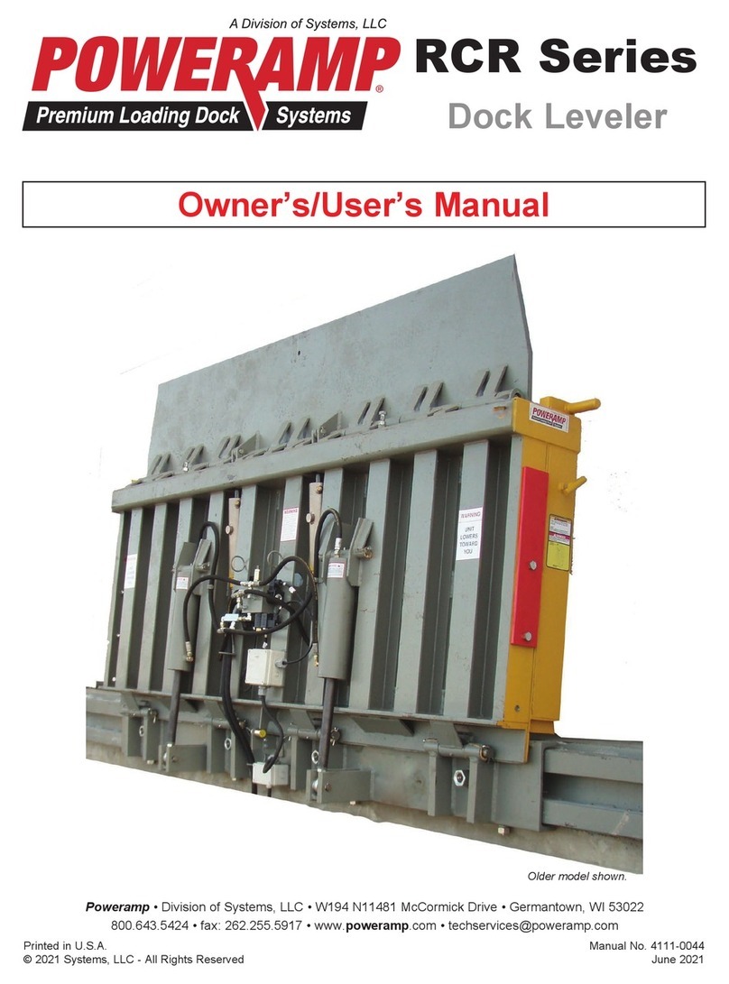
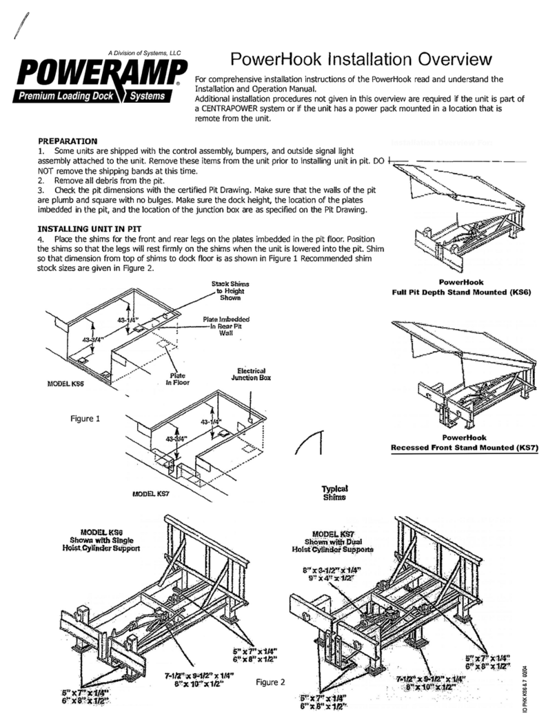
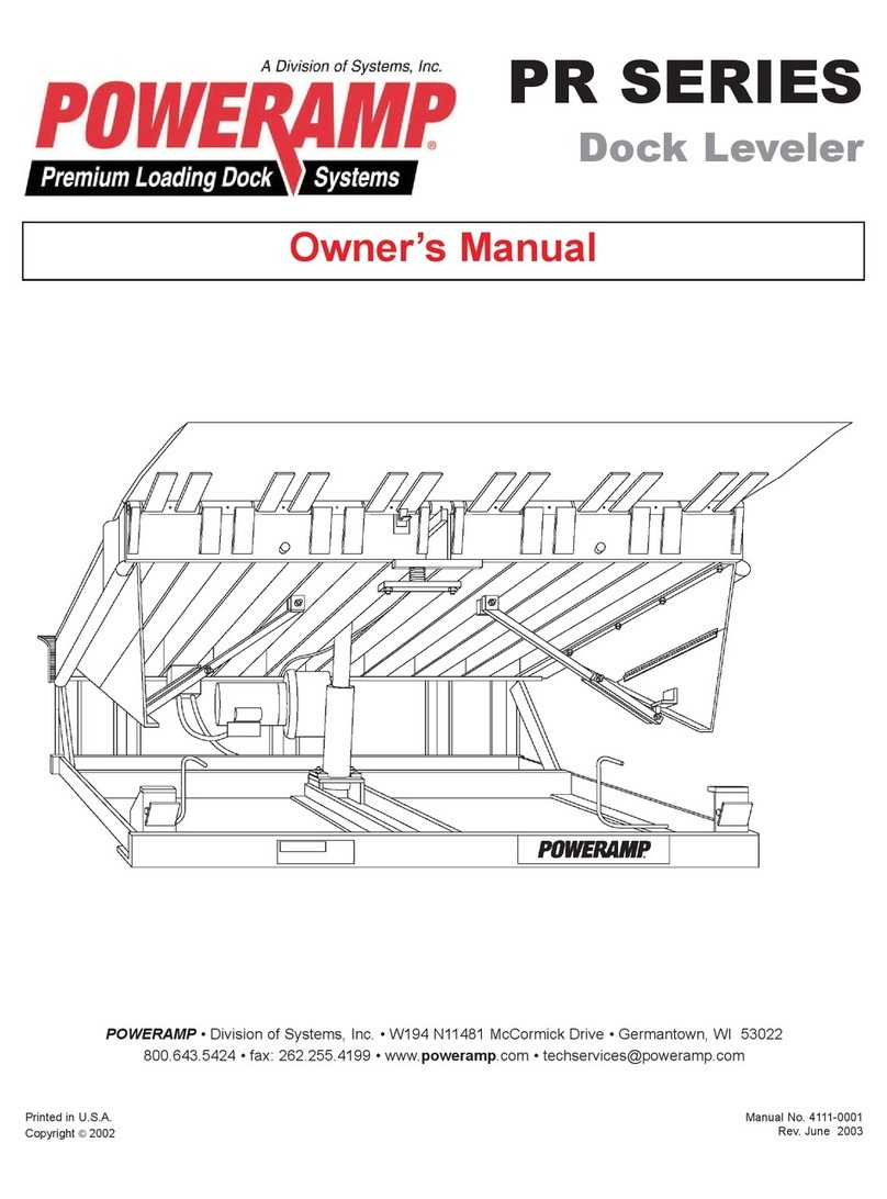
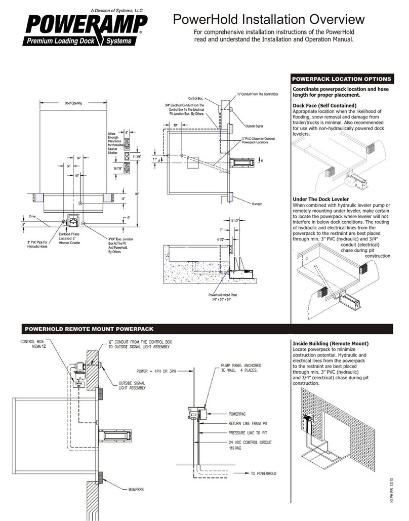
Poweramp PowerLift User manual

Printed in U.S.A.
Copyright © 2017
Manual No. 4111-0078
April 2017
POWERAMP®• Division of Systems, Inc. • W194 N11481 McCormick Drive • Germantown, WI 53022
PowerLift
Truck Leveler
Surface Mount
Owner’s / User’s Manual

Page
Safety
Recognize Safety Information ............................................................. 1
General Operational Safety Precautions ............................................ 1
Operational Safety Precautions........................................................... 2
Maintenance Safety Precautions......................................................... 4
Safety Decal’s........................................................................................ 5
Owner’s User’s Responsibilities ......................................................... 6
Introduction
General Information,............................................................................. 7
Truck Leveler Stock Specifications .................................................... 7
Component Identification..................................................................... 8
Theory ................................................................................................... 8
Installation
Prepare Surface .................................................................................... 9
Prepare Truck Leveler ......................................................................... 10
Install Truck Leveler ............................................................................ 11
Install Control Panel and Wiring ........................................................ 12
Put New Leveler Into Service.............................................................. 14
Operation
Operating Instructions ........................................................................ 16
Maintenance
Service Truck Leveler Safely .............................................................. 17
Periodic Maintenance .......................................................................... 18
Adjustments
Adjust Main System Pressure ............................................................ 20
Adjust Down Speed Control ............................................................... 20
Troubleshooting
Troubleshooting................................................................................... 22
Parts
Electrical ............................................................................................... 24
Control Box .......................................................................................... 25
Power Pack, Hoses, Cylinders ........................................................... 26
Truck Leveler........................................................................................ 28
Miscellaneous
Customer Information ......................................................................... 29
Warranty................................................................................ Back Cover
Table of Contents

1
4111-0078 — April 2017
SAFETY
The use of the word DANGER signifies the
presence of an extreme hazard or unsafe practice
which will most likely result in death or severe
injury.
The use of the word WARNING signifies the
presence of a serious hazard or unsafe practice
which could result in death or serious injury.
The use of the word CAUTION signifies possible
hazard or unsafe practice which could result in
minor or moderate injury.
Do not start the equipment until all unauthorized
personnel in the area have been warned and have
moved outside the operating zone.
Remove any tools or foreign objects from the
operating zone before starting.
Keep the operating zone free of obstacles that could
cause a person to trip or fall.
Read and understand the Owner’s/User’s manual
and become thoroughly familiar with the equipment
and its controls before operating the truck leveler.
Never operate a truck leveler while a safety device or
guard is removed or disconnected.
Never remove DANGER, WARNING, or CAUTION
signs or decal’s on the equipment unless replacing
them.
General Operational Safety PrecautionsRecognize Safety Information
The Safety-Alert Symbol This is the safety alert
symbol. It is used to alert you to the potential
physical injury hazard. Obey all safety messages
that follow this symbol to avoid possible death or
injury.
Safety - Alert Symbol
The use of the word NOTICE indicates information
considered important, but not hazard-related, to
prevent machine or property damage.
Indicates a type of safety sign, or separate panel
on a safety sign, where safety-related instructions
or procedures as described.
O
p
e
r
a
t
i
n
g
Z
o
n
e
TOLERANCES
(UNLESS OTHERWISE NOTED)
FRACTIONAL: 1/32"
DECIMAL:
.00 = .01"
.000 = .005"
ANGULAR: 1
DRAWN BY CHECKED BY
DRAWING NO.
DATE
BDK 4/24/2017
L o a d i n g D o c k E q u i p m e n t
P O W E R A M P
M C G U I R E
D L M
This print is the proper ty of Systems, Inc . and represents a propriet ary article in whi ch Systems, Inc. re tains any and all pa tent and other ri ghts, including ex clusive rights
ofuse and/or manufactureand/orsale. Possessionof this print does notconvey any permissionto reproduce,print or manufacturet he article or articles shown the rein,
such permission to b e granted only by w ritten authoriza tion signed by a n officer or other auth orized agent of Sy stems,Inc. ther eof.
MATERIAL STOCK NO.
ISO VIEW STORED
POSITION
SMTL - 65,000#

24111-0078—April 2017
SAFETY
Stay clear of truck leveling device when transport
vehicle is entering or leaving area.
Do not move or use the truck leveling device if
anyone is under or in front of it.
Keep hands and feet clear of pinch points. Avoid
putting any part of your body near moving parts.
Stay clear of truck leveling device when transport
vehicle is entering or leaving area.
Do not move or use the truck leveling device if
anyone is under, on or in front of it.
Keep hands and feet clear of pinch points. Avoid
putting any part of your body near moving parts.
Chock/restrain all transport vehicles, Never
remove the wheel chocks until loading or
unloading is finished and transport driver has been
given permission to drive away.
Do not use a broken or damage truck leveling
device. Make sure proper service and
maintenance procedures have been performed
before using.
Make sure lip overlaps onto transport vehicle bed
at least 4 in. (102 mm).
Keep a safe distance from both side edges.
Operational Safety PrecautionsOperational Safety Precautions
Learn the safe way to operate this equipment. Read and understand the
manufacturer’s instructions. If you have any questions, ask your supervisor.

3
4111-0078 — April 2017
SAFETY
Do not use truck leveling device if transport
vehicle is too high or too low.
Do not overload the truck leveling device.
Do not operate any equipment while under the
influence of alcohol or drugs.
Do not leave equipment or material unattended on
truck leveling device.

44111-0078—April 2017
SAFETY
ALWAYS disconnect electrical power source and
ground wire before welding on truck leveler.
DO NOT ground welding equipment to any hydraulic
or electrical components of the truck leveler. Always
ground to the truck leveler frame.
Always post safety warnings and barricade the
work area at truck level and dock level to prevent
unauthorized use of the unit before maintenance
is complete.
Hydraulic and electrical power must be OFF when
servicing the equipment. For maximum protection,
use an OSHA approved locking device to lock
out all power sources. Only the person servicing
the equipment should have the key to unlock the
device.
ALWAYS stand clear of truck leveler when working
in front of or behind the truck leveler.
DO NOT grind or weld if hydraulic fluid or other
flammable liquid is present on the surface to be
ground or welded
DO NOT grind or weld if uncontained hydraulic
fluid or other flammable liquid is present. Stray
sparks can ignite spills or leaks near the work area.
Always clean up the oil leaks and spills before
proceeding with grinding or welding.
Always keep a fire extinguisher of the proper type
nearby when grinding or welding.
Maintenance Safety Precautions
1.50"
3.00"
Decal Size: 1.5 x 3
File Name: 1751-0736 Rev A
Arc Flash and
Shock Hazard
PPE [Personal Protection
Equipment] Required
De-energize equipment before
working on or inside. Do not
open cover without appropriate
PPE. Refer to NFPA 70E for
PPE requirements. This panel
may contain more than one
power source.
Hazardous Voltage
Will Result in Death
or Serious Injury
1751-0736 Rev A

5
4111-0078 — April 2017
SAFETY
Decal Size: 4 x 2
File Name: 1751-1018 Rev A
CRUSH HAZARD
DO NOT
DO NOT REMOVE
extend hydraulic cylinder by a means other than
hydraulic power.
hydraulic cylinder until you refer to
owner’s/user’s manual for proper maintenance
procedures.
Failure to comply will result in death or serious injury.
1751-1018 Rev A

64111-0078—April 2017
OWNER’S/USER’S RESPONSIBILITIES
1) The manufacturer shall provide to the initial
purchaser and make the following information
readily available to the owners/users and their
agents, all necessary information regarding Safety
Information, Operation, Installation and Safety
Precautions, Recommended Initial and Periodic
Inspections Procedures, Planned Maintenance
Schedule, Product Specifications, Troubleshooting
Guide, Parts Break Down, Warranty Information,
and Manufacturers Contact Information, as well as
tables to identify the grade(slope) for all variations
of length or configuration of the truck leveling
device and information identifying the maximum
uncontrolled drop encountered when sudden
removal of support while in the working range of the
equipment.
2) When selecting loading truck safety equipment, it is
important to consider not only present requirements
but also future plans and any possible adverse
conditions, environmental factors or usage. The
owners/users shall provide application information
to the manufacturer to receive recommendations on
appropriate equipment specifications and capacity.
3) The Owner/User must see all nameplates, placards,
decals, instructions and posted warnings are in
place and legible and shall not be obscured from
the view of the operator or maintenance personnel
for whom such warnings are intended for. Contact
manufacturer for any replacements.
4) Truck leveling devices may become hazardous
if the manufacturer’s instructions regarding
modifications or adjustments are not followed.
Modifications or alterations of truck leveling devices
shall only be made with prior written approval from
the original manufacturer. These changes shall
be in conformance with all applicable provisions
of the MH30.1 standard and shall also satisfy all
safety recommendations of the original equipment
manufacturer of the particular application.
5) The owner/user should recognize the inherent
dangers of the interface between the loading truck
and the transport vehicle. The owner/ user should,
therefore, train and instruct all operators in the safe
operation and use of the loading truck equipment in
accordance with manufacturer’s recommendations
and industry standards. Effective operator
training should also focus on the owner’s/user’s
company policies, operating conditions and the
manufacturer’s specific instructions provided with
the truck leveling device. Maintaining, updating and
retraining all operators on safe working habits and
operation of the equipment, regardless of previous
experience, should be done on a regular basis and
should include an understanding and familiarity with
all functions of the equipment. Owners/users shall
actively maintain, update and retrain all operators
on safe working habits and operations of the
equipment.
6) An operator training program should consist of, but
not necessarily be limited to, the following:
a) Select the operator carefully. Consider the
physical qualifications, job attitude and aptitude
b) Assure that the operator reads and fully
understands the complete manufacturer’s
owners/users manual.
c) Emphasize the impact of proper operation upon
the operator, other personnel, material being
handled, and equipment. Cite all rules and why
they are formulated.
d) Describe the basic fundamentals of the truck
leveling device and components design as
related to safety, e.g., mechanical limitation,
stability, functionality, ect.
e) Introduce the equipment. Show the control
locations and demonstrate its functions.
Explain how they work when used properly and
maintained as well as problems when they are
used improperly.
f) Assure that the operator understands the
capacity rating, nameplate data, placards and all
precautionary information appearing on the truck
leveling device.
g) Supervise operator practice of equipment.
h) Develop and administer written and practical
performance tests. Evaluate progress during and
at completion of the course.
i) Administer periodic refresher courses. These
may be condensed versions of the primary
course and include on-the-job operator
evaluation.
7) Loading truck safety equipment should never be
used outside of its vertical working range, or outside
the manufacturer’s rated capacity. It shall also be
compatible with the loading equipment and other
conditions related to truck activity. Please consult
the manufacturer if you have any questions as to
the use, vertical working range or capacity of the
equipment. Only properly trained and authorized
personnel should operate the equipment.
8) It is recommended that when the transportation
vehicle is positioned as close as practical to the
truck leveling device and in contact with both
bumpers, there shall be a minimum of 4.00 inches
(100mm) overlap between the front edge of the
lip and the edge of the floor or sill of the transport
7
4111-0078 — April 2017
INTRODUCTION
General Information
PowerLift Series Truck Levelers are available in the
following sizes, weight capacities, and options:
Width:
up to12'6"(3810mm)
Length
Consult Factory
Capacity (CIR*)
50,000 lb (22 680 kg)
55,000 lb (24 948 kg)
60,000 lb (27 216kg)
65,000 lb (22 484 kg)
* CIR (Comparative Industry Rating)
The PowerLift truck has an electrical controls, which
allows operation of the truck leveler functions. Each
PowerLift leveler unit and control panel have been
factory assembled and tested to ensure satisfactory
operation.
To illustrate which connections are to be made
in the field at installation, electrical drawings and
hose drawings are included with each order or by
contacting Technical Services.
Once again, thank you and congratulations on your
purchase of a Poweramp PowerLift Truck Leveler.
Truck Leveler Stock Specifications
Congratulations on your choice of a Poweramp Truck
Leveler. This manual covers the PowerLift Truck
Leveler Surface Mount
Designed by Poweramp to be a marvel of simplicity
and efficiency, your truck leveler, when properly
installed, will provide many years of trouble-
free performance with an absolute minimum of
maintenance. To obtain maximum performance and
longest possible use, a simple program of preventive
maintenance is recommended.
vehicle at all times during the loading and
unloading process.
9) When goods are transferred between the loading
truck and the transport vehicle, this vehicle
shall have the brakes and wheel chocks or
positive restraints that provide the equivalent
protection of wheel chocks shall be engaged. It is
recommended that transport vehicles with air-ride
suspension systems shall have its air exhausted
prior to performing loading and unloading
operation to minimize transport vehicle bed drop.
10) Manufacturer’s recommended maintenance and
inspection of all truck leveling devices shall be
performed in conformance with the following
practices: A planned Maintenance schedule
program must be followed, only trained and
authorized personnel shall be permitted to
maintain, repair, adjust and inspect truck leveling
devices, and only the use of original equipment
manufacturer parts, manuals, maintenance
instructions, labels, decals and placards or their
equivalent. Written documentation of maintenance,
replacement parts or damage should be kept. In the
event of damage, notification to the manufacturer is
required.
11) Loading truck devices that are structurally damaged
or has experienced a sudden loss of support while
under load, such as might occur when a transport
vehicle is pulled out from under the truck leveling
device, shall be removed from service, inspected
by a manufacturer’s authorized representative, and
repaired or replaced as needed or recommended
by the manufacturer before being placed back in
service.

84111-0078—April 2017
Component Identification
A — Lip Approach (Optional) B — Cylinder Towers C —Truck Leveler D — Power Pack E — Control Box
A — Trunnion Hinge Weldment F — Toe Guards
The PowerLift truck leveler uses a dual push button
operation for ease of use.
The truck leveler is operated by:
1.) Depress RAISE button (F) on the control panel
to activate an electric motor which drives the hydraulic
pump. The hydraulic pump forces oil in the truck
levelers main platform cylinders(B), causing the unit to
raise to the desired height of the transport vehicle.
2) Depress the LOWER button(G) on the control
panel which activates a control solenoid that allows
the hydraulic oil to return to the reservoir and lower the
unit.
THEORY
INTRODUCTION
A — Trunnion Hinge Weldment
G
A
F
C
D
B
F
E
F

9
4111-0078 — April 2017
INSTALLATION
Before installing the truck leveler on the surface, the
following must be performed:
1. Remove all debris from the surface and sweep it
clean.
2. Check the entire truck leveler surface for proper
construction according to approved/certified
drawings.
3. Confirm all components are accounted for.
4. Have 4 blocks at least 8 inches tall and able to
hold 1 ton of weight to set the truck leveler on
once it is unloaded from the transport vehicle.
5
72
117
72
144
DRIVE
FINISHED FLOOR
171
167 7/8
99
49 1/2
49 1/2
72
144
TOE GUARDS
TRUNNION HINGE WELDMENT
3/8 4-12
CYLINDER TRUNNION BASE
-2 PER PIT
-USE 5/8" CONCRETE ANCHORS (3 PER TRUNNION)
DIVISION OF SYSTEMS INC., GERMANTOWN WI
DATE
DWG. NO. REV
MATERIAL
DRN BY
CHK BY
R
1.NOTE: DURING PLACEMENT OF CYLINDER TRUNNION
BASES, MAKE SURE THAT THE CYLINDERS ARE
VERTICAL WHEN LEVELER IS IN LOWEST POSITION.
2. ALL MEASUREMENTS ARE IN INCHES
SURFACE MOUNTED TRUCK LEVELER -ADOHR FARMS
14' LONG - INSTALLATION GUIDE
8/31/95
GSD
SMTLIGAF
Orientate the trunnion with the two bolts
toward the dock face.(shown with straps
removed)
Post safety warnings and barricade the work
area at truck level and ground level to prevent
unauthorized use of the truck leveler before
installation has been completed.
Only trained installation professionals with the
proper equipment should install this product.
Truck leveler must be set on 8 inch block when
unloading to protect components under the leveler.
* Refer to OSHA regulation 1910.146. Confine Space
* Refer to OSHA regulation 1910.147. Lockout/Tagout
The truck leveler is heavy. Use chains and a lifting
device with the appropriate lifting capacity and
reach.
Prepare Surface
A
A
B
A—Cylinder Trunnion Base B—Trunnion Hinge Weldment

10 4111-0078—April 2017
Prepare Truck Leveler
INSTALLATION
FIGURE #1
FIGURE #2

11
4111-0078 — April 2017
1. Remove any control panel, parts and bumpers
that may be banded to the truck leveler.
2. Install the truck bumpers as required.
3. Make sure the mounting hardware or lifting hooks
have the appropriate lifting capacity for the truck
leveler, check the Bill Of Landing(BOL) for actual
shipping weight.
4. Attach lifting chains to the four corners of the
truck leveler, (Fig 1.) and to a lifting device (i.e.,
hoist or fork truck) having the appropriate lifting
capacity and reach.
5. (Optional) Place the truck leveler on minimum
8 inch tall wood blocks, if readjustments are
needed to insert the truck leveler into the door
opening (Fig. 2).
6. Once truck leveler is inside the building, or close
INSTALLATION
Following start-up or if the platform is raised using
an external lifting device or the hydraulic system
is opened to atmosphere, air will enter into the
hydraulic system.
Whenever this happens, purge air from hydraulic
system fully.
FIGURE #3
Level the unit front to rear and left to right, shim as
required to obtain a level platform. Weld the shim
and touch up with paint as needed
to the install position, set the unit on the 8 inch
blocks to prep the hydraulic installation.
7. Locate and anchor the hydraulic trunnions with 5/8
x 5 anchor bolts, job specific drawings Torque all
the bolts to the vendor specifications.
8. Remove and position the trunnion hinge weldment.
Anchor to the approach with 5/8 x 5 anchors.
Torque to the vendor specifications(FIG #3)
9. Install the "T" bar from the parts box and partially
install into both main cylinders(FIG #4).
10. Install the long hose(A) from the power pack and
connect to the "T" fitting under the truck leveler.
11. Using an appropriate lifting device, lower truck
FIGURE #4
The truck leveler is heavy. Use chains and a lifting
device with the appropriate lifting capacity and
reach.
DO NOT grind or weld if hydraulic fluid or other
flammable liquid is present on the surface to be
ground or welded.
DO NOT grind or weld if uncontained hydraulic
fluid or other flammable liquid is present. Stray
sparks can ignite spills or leaks near the work area.
Always clean up the oil leaks and spills before
proceeding with grinding or welding.
Always keep a fire extinguisher of the proper type
nearby when grinding or welding.
A

12 4111-0078—April 2017
INSTALLATION
Install Truck Leveler
leveler on to the hydraulic trunnions and the rear
hinge trunnion weldment.(FIG# 5)
FIGURE #5
17. Anchor the power unit in place, using 3/8 x 3 an-
chor bolts, torque the bolts to the vendor specifica-
tions.
18. Mount the control box .
19. Complete the wiring of the motor and field
connections as per drawings supplied.
20. Verify that the reservoir is full.
12. Using the pins provided connect the platform to
the hinge trunnions weldment (Fig #6).
13. Level the platform using the "T" bars. Turn "T"
bars clockwise all the way in then turn counter
clock wise to level the platform left to right.
14. Install the straps on the cylinder trunnions.
15. Disconnect the lifting devices.
16. Locate the power unit and mount the power unit
per the drawing supplied with the unit.
FIGURE #6
NOTE: To ensure normal operation of the truck
leveler, use only Aircraft Hydraulic Fluid designed to
meet or exceed military specification MIL-H-5606-G. It
is recommended that the following hydraulic fluids be
used:
• Ultra Vis Hvi 15
• Aero Shell Fluid 4 or Fluid 41
• Mobile Aero HFA Mil-H5606 G or Aero HF
• Texaco Aircraft Hydraulic Oil 15 or 5606
• Exxon Univis J13
21. These fluid brands can be mixed together.
Mixing with fluids that do not meet or exceed
MIL-H-5606-G may damage the equipment and
WILL void warranty. Use of hydraulic fluids with
equivalent specifications to those listed here are
acceptable.
22. Check all hose routing are secured. Inspect for
leaks on all hose connections.
23. When all welding has been completed, paint all
the welds and shims.

13
4111-0078 — April 2017
INSTALLATION
General Lay out, actual product may differ from pictorial

14 4111-0078—April 2017
INSTALLATION
1. Check that the leveler is flush with the surface
and that the platform lip/ front hinge trunnion
weldment contacts approach evenly.
2. If an excessive transition exists between the truck
leveler and lip/ front hinge trunnion weldment
to the approach, contact Technical Services for
further instructions.
3. Turn the main electrical power ON.
4. Depress the RAISE button and hold until leveler
platform is fully raised.
5. Release RAISE button, the platform will stop and
stay at that position.
Put New Truck Leveler Into Service
6. To lower the platform depress and hold the
LOWER button, the platform will lower to the
stored position.
7. Perform steps 4-6 at least four times make sure
the leveler functions properly, purging any air in
the systems and that there is no binding.
TOLERANCES
(UNLESS OTHERWISE NOTED)
FRACTIONAL: 1/32"
DECIMAL:
.00 = .01"
.000 = .005"
ANGULAR: 1
DRAWN BY CHECKED BY
DRAWING NO.
DATE
BDK 4/24/2017
L o a d i n g D o c k E q u i p m e n t
P O W E R A M P
M C G U I R E
D L M
This print is the proper ty of Systems, Inc. and repr esents a proprietar y article in which Syste ms, Inc. retains any a nd all patent and ot her rights, including exc lusive rights
ofuse and/or manufactureand/or sale.Possessionof this print does not conveyany permission to reproduce,printor manufacture the article or artic les shown therein,
such permission to be granted on ly by written authorizati on signed by an officer or other auth orized agent of Systems,Inc . thereof.
MATERIAL STOCK NO.
ISO VIEW RAISED
POSITION
SMTL - 65,000#
TOLERANCES
(UNLESS OTHERWISE NOTED)
FRACTIONAL: 1/32"
DECIMAL:
.00 = .01"
.000 = .005"
ANGULAR: 1
DRAWN BY CHECKED BY
DRAWING NO.
DATE
BDK 4/24/2017
L o a d i n g D o c k E q u i p m e n t
P O W E R A M P
M C G U I R E
D L M
This print is the proper ty of Systems, Inc. and repr esents a proprietar y article in which Syst ems, Inc. retains any a nd all patent and ot her rights, including exc lusive rights
ofuse and/or manufactureand/or sale.Possessionof this print does not conveyany permission to reproduce,printor manufacture the article or artic les shown therein,
such permission to be granted on ly by written authorizati on signed by an officer or other auth orized agent of Systems,Inc . thereof.
MATERIAL STOCK NO.
ISO VIEW STORED
POSITION
SMTL - 65,000#
NOTE: The truck leveler will lower very slowly with out
the transport vehicle on it.
8. To adjust the down speed, turn the flow control (A)
clock wise to slow the unit down and counter clock
wise to increase the speed.
9. The unit has safety velocity fuses on both main
cylinders incase of a hose break.
NOTE: If the flow control is turned out too far the unit
will lock up under its own weight. Adjust the flow con-
trol clock wise and run the unit again.
A

15
4111-0078 — April 2017
INSTALLATION
This page left intentionally blank

16 4111-0078—April 2017
OPERATION
1. Check to make sure transport vehicle is positioned
squarely against both dock bumpers.
2. Instruct driver to remain at the dock until the
loading or unloading process has been completed.
3. Chock the transport vehicle wheels or use the
vehicle restraint if available.
4. Depress RAISE button (F) on the control panel to
raise to the desired height of the transport vehicle.
5. Depress the LOWER button(G) on the control
panel which lower the unit to the desired height of
the transport vehicle.
6. When loading or unloading is finished, lower the
platform by depressing and holding LOWER
button (G) until the unit is completely stored.
7. Remove chocks from transport vehicle wheels or
release the vehicle restraint if used.
8. Indicate to driver that transport vehicle may leave
the dock.
Stay clear of truck leveler when transport vehicle
carrier is entering or leaving truck area.
DO NOT move or use the truck leveler if anyone is
under, on or in front of leveler.
Keep hands and feet clear of pinch points. Avoid
putting any part of your body near moving parts.
Only trained personnel should operate the truck
leveler.
DO NOT use a broken or damaged truck leveler.
Make sure proper service and maintenance
procedures have been performed on leveler before
using.
Transport vehicle wheels must be chocked unless
the vehicle restraint is used. Never remove the
wheel chocks until loading/unloading is finished
and transport vehicle driver has been given
permission to leave.
Make sure platform lip rests on the transport
vehicle bed with at least 4 in. (102 mm) of overlap.
Maintain a safe distance from side edges of leveler
during the loading/unloading process.
Operating Instructions
The PowerLift Truck Leveler is designed to
compensate for a maximum + 24 in.(610mm)* of
height difference between the loading dock floor
and the approach.
*Service height may vary with design specifications
DO NOT overload the truck leveler.
DO NOT operate any equipment while under the
influence of alcohol or drugs.
DO NOT leave equipment or material unattended
on the truck leveler.
TOLERANCES
(UNLESS OTHERWISE NOTED)
FRACTIONAL:
1/32"
DECIMAL:
.00 =
.01"
.000 =
.005"
ANGULAR:
1
DRAWN BY CHECKED BY
DRAWING NO.
DATE
BDK 4/24/2017
L o a d i n g D o c k E q u i p m e n t
P O W E R A M P
M C G U I R E
D L M
This print is t he property of Systems , Inc. and represents a proprietar y article in which Syst ems, Inc. retains any a nd all patent and ot her rights, including exclusive r ights
of useand/or manufactureand/or sale. Possessionof this printdoes not convey any permissionto reproduce,print or manufacturethe a rticle or articles shown the rein,
such permissio nt ob eg ranted only by written auth orization signed by an office ro rot her authorized agent of Syste ms,Inc. thereof.
MATERIAL STOCK NO.
ISO VIEW RAISED
POSITION
SMTL - 65,000#
24in. (610mm)
F
G

17
4111-0078 — April 2017
OPERATION
Service Truck Leveler Safely
Whenever performing maintenance under the
truck leveler platform, support the platform with the
alternate means. Lock Out/Tag Out the power supply
with OSHA approved lockout/tag out device* (B&C).
Only the person servicing the equipment should have
the capability to remove the lockout/tag out devices.
The Tag out devices* must inform that repairs are in
process and clearly state who is responsible for the
lockout condition.
* Refer to OSHA regulation 1910.146. Confine Space
* Refer to OSHA regulation 1910.147. Lockout/Tagout
A— Operating Zone B —Tag Out Device C —Lock Out Device
When service under the truck leveler is required,
always lock all electrical disconnects in the OFF
position after raising the platform and support
by alternate means This alternate means may
include, but not limited to a boom truck, fork truck,
stabilizing bar or equivalent.
Always stand clear of the truck leveler when in
motion.
Always post safety warnings and barricade the
work area at truck level and dock level to prevent
unauthorized use of the truck leveler before
maintenance is complete.
O
p
e
r
a
t
i
n
g
Z
o
n
e
TOLERANCES
(UNLESS OTHERWISE NOTED)
FRACTIONAL: 1/32"
DECIMAL:
.00 = .01"
.000 = .005"
ANGULAR: 1
DRAWN BY CHECKED BY
DRAWING NO.
DATE
BDK 4/24/2017
L o a d i n g D o c k E q u i p m e n t
P O W E R A M P
M C G U I R E
D L M
This print is the proper ty of Systems, Inc . and represents a propriet ary article in whi ch Systems, Inc. re tains any and all pa tent and other ri ghts, including ex clusive rights
ofuse and/or manufactureand/orsale. Possessionof this print does notconvey any permissionto reproduce,print or manufacturet he article or articles shown the rein,
such permission to b e granted only by w ritten authoriza tion signed by a n officer or other auth orized agent of Sy stems,Inc. ther eof.
MATERIAL STOCK NO.
ISO VIEW STORED
POSITION
SMTL - 65,000#
B
C
A

18 4111-0078—April 2017
Regular maintenance must be performed on a weekly
and quarterly schedule. Follow all safety precautions.
Weekly Maintenance
• Clean from around and on top of truck leveler,
dirt and debris that would cause abnormal
operation
• Check the hydraulic fluid level on the site
glass(A). Fill with only recommended fluids P.12.
• Check hose connection for leaking fluids, replace
or repair as needed.
• Check fluid filter gage replace when indicated on
dial (B).
• Operate the truck leveler through the complete
operating cycle to maintain lubrication.
Quarterly Maintenance
• Perform Weekly Maintenance Items
Lubricate the following areas with white lithium
grease:
• Trunnion Hinge Weldment and pins(C).
• Platform main cylinder pivots(D).
• Verify main systems pressure is set at 2100 psi(E)
See Adjustments.
• Check all anchors are torqued to vendor
specifications.
• Inspect the platform hinge and the lip hinge areas.
Look for cracks in the welds or damage. The
hinge areas must be kept free of dirt and debris.
Build-up of foreign material in the hinge areas will
cause abnormal operation.
• Inspect the area under the platform, look for cracks
in the welds or damage. Build-up of foreign
material in this area may damage components,
causing abnormal operation.
MAINTENANCE
Periodic Maintenance
Table of contents
Other Poweramp Lifting System manuals

Poweramp
Poweramp CentraAir User manual

Poweramp
Poweramp CM Series User manual

Poweramp
Poweramp EH Series User manual

Poweramp
Poweramp PowerHold Installation guide

Poweramp
Poweramp PowerHook Installation guide

Poweramp
Poweramp LMP Series User manual

Poweramp
Poweramp CentraAir User manual

Poweramp
Poweramp PR User manual

Poweramp
Poweramp Bar Lift User manual

Poweramp
Poweramp LHP Series User manual