Powerbuilt 648990 User manual

Bubble Flaring Tool Kit
Appareil à collets battus
Juego de herramientas abocardadoras
6PC.
648990
Distribution & Returns
©2018, Alltrade Tools, LLC
Reno, NV 89508
www.powerbuilt.com
Made in / Fabriqué en / Hecho en Taiwan
FOR WARRANTY / SERVICE
POUR LA GARANTIE / LE SERVICE
PARA GARANTÍA / SERVICIO
1-800-423-3598

1
Bubble Flaring Tool Kit
INSTRUCTIONS
NOTE: It is important to prepare the end of the tubing before flaring as described
in step 1. Failure to do so will ensure unsatisfactory results.
1. Cut the end of tubing off squarely with a tubing cutter. Do NOT attempt to flare tubing that has
been cut with a hacksaw or other device that is not specifically designed for cutting brake tubing.
See figure a.
2. Use a reamer, round file or pocket knife blade to deburr the inside diameter of the tubing. See
figure b. Round off (chamfer) the edge of the outside diameter of the tubing using a small file.
See figure c.
3. If there will not be an opportunity to install a flare nut (if used) from the other end of the tubing at
a later time, slip the required flare nut over the prepared end of the tubing and position it out of
the way.
4. Insert the tubing through the hole in the flaring bar that matches the diameter of the tubing.
Position the tubing so that the end is level with the surface of the flaring bar as shown and
tighten wing nuts. See figure d.
5. Select the correct size flaring adapter and thread securely onto the threaded nut on the steel
flaring yoke as shown. The nipple of the flaring adapter should fit into the inner diameter of the
tubing to be flared. See figure e.
Figure (a) Figure (b)
Figure (c) Figure (d)
Figure (e)

2
6. Position the flaring yoke and adapter directly over the hole in the end of the tubing. See figure f.
Slowly turn the “T” handle of the flaring yoke clockwise while guiding the adapter into the hole
in the tubing. See figure g.
7. Tighten the “T” handle until the tapered surface of the flaring adapter is flush with the tapered
surface of the hole in the flaring yoke. See figure h.
8. Turn the “T” handle of the flaring yoke counterclockwise to loosen until the adapter clears the
newly flared tubing end. Loosen the wing nuts on the flaring bar and remove the tube from the
flaring bar. Examine the bubble flare for cracks, distortion or other faults. If faults are found, cut
off tubing end and repeat flaring process. See figures i and j.
Figure (f) Figure (g)
Figure (h) Figure (i)
Figure (j)

3
APPAREIL À COLLETS BATTUS
MODE D’EMPLOI
REMARQUE : Il est important de préparer l’extrémité du tuyau avant de l’évaser en
suivant les indications de l’étape 1 pour éviter tout résultat insatisfaisant.
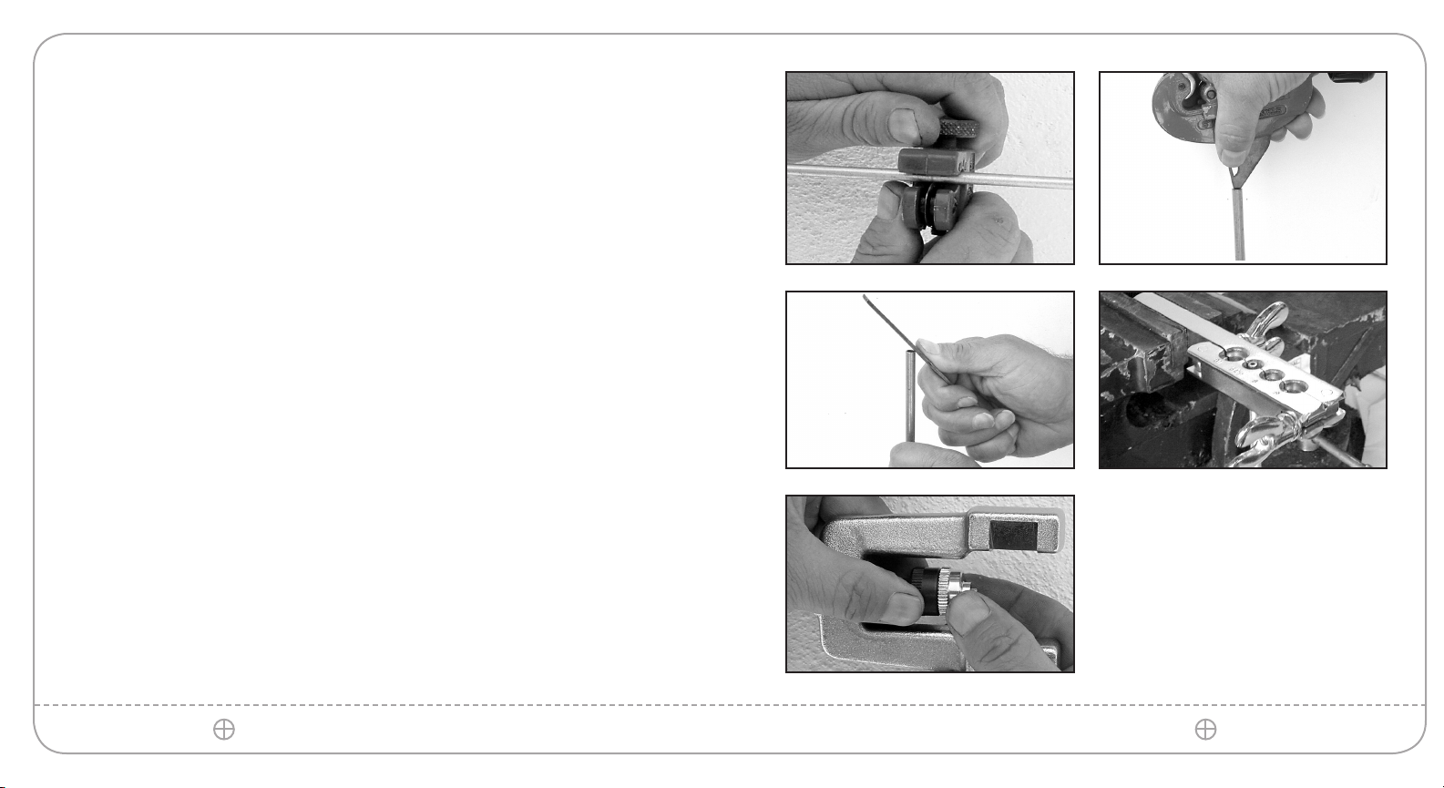
1. Couper nettement l’extrémité du tuyau à l’aide d’un coupe-tube. Ne PAS tenter d’évaser des tuyaux
coupés avec une scie à métaux ou tout autre dispositif qui n’est pas spécifiquement adapté à la coupe
des conduites du système de freinage. Voir figure a.
2. À l’aide d’un alésoir, d’une lime ronde ou d’une lame de canif, ébavurer le diamètre intérieur du tuyau.
Voir figure b. Arrondir (chanfreiner) le rebord du diamètre extérieur du tuyau à l’aide d’une petite lime.
Voir figure c.
3. S’il n’est pas possible d’introduire par la suite un écrou évasé (si utilisé) par l’autre extrémité du
tuyau, glisser en position excentrique l’écrou évasé requis sur l’extrémité du tuyau qui vient d’être
préparé.
4. Insérer le tuyau dans le trou de la barre à collets de même diamètre. Positionner l’extrémité du tuyau à
niveau avec la surface de la barre à collets, comme indiqué, et serrer les écrous à oreilles. Voir figure
d.
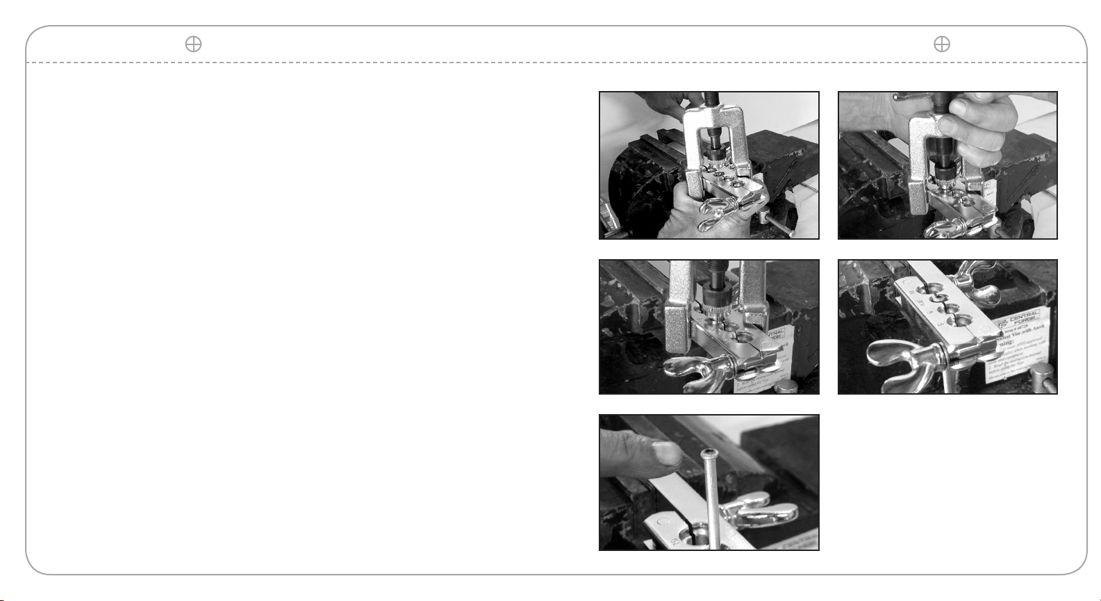
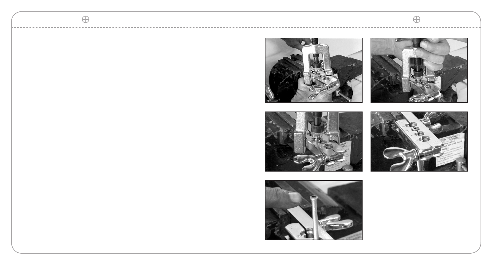
5. Sélectionner un embout d’évasement de la taille requise et visser fermement sur l’écrou fileté de la
fourche à collets en acier, comme indiqué. Le mamelon de l’embout d’évasement doit correspondre au
diamètre intérieur du tuyau à évaser. Voir figure e.
Figure (a) Figure (b)
Figure (c) Figure (d)
Figure (e)

4
6. Positionner la fourche à collets et l’embout d’évasement directement sur le trou à l’extrémité du
tuyau. Voir figure f. Tourner lentement la poignée en « T » de la fourche à collets dans le sens
horaire tout en guidant l’embout dans le trou du tuyau. Voir figure g.
7. Serrer la poignée en « T » jusqu’à ce que la surface conique de l’embout d’évasement soit
alignée sur la surface conique du trou de la fourche à collets. Voir figure h.
8. Tourner poignée en « T » de la fourche à collets dans le sens antihoraire pour la desserrer
jusqu’à ce que l’embout libère l’extrémité du tuyau qui vient d’être évasée. Desserrer les écrous
à oreilles de la barre à collets et retirer le tuyau de la barre. Vérifier l’absence de fissures,
déformations ou autres défauts sur le collet. En cas de défauts, couper l’extrémité du tuyau et
recommencer la procédure d’évasement. Voir figures i et j.
Figure (f) Figure (g)
Figure (h) Figure (i)
Figure (j)

5
JUEGO DE HERRAMIENTAS ABOCARDADORAS
INSTRUCCIONES
NOTA: Es importante preparar el extremo de la tubería antes de abocardarla tal como se
describe en el paso 1. De lo contrario se obtendrán resultados insatisfactorios.
1. Corte el extremo de la tubería uniformemente con un cortatubos. NO trate de abocardar una tubería que
ha sido cortada con segueta u otro artefacto no específicamente diseñado para cortar tuberías de frenos.
Consulte la figura a.
2. Use un escariador, lima redonda o una navaja para eliminar las rebabas en el diámetro interno de la
tubería. Consulte la figura b. Acabe (bisele) el borde del diámetro externo de la tubería con una lima
pequeña. Consulte la figura c.
3. Si posteriormente no se podrá instalar una tuerca cónica (si se usara) desde el extremo opuesto de la
tubería, deslice la tuerca cónica requerida sobre el extremo preparado de la tubería y colóquela de modo
que no estorbe.
4. Introduzca la tubería por el orificio de la barra abocardadora que coincide con el diámetro de la tubería.
Coloque la tubería de modo que el extremo quede nivelado con la superficie de la barra tal como se
muestra y apriete las tuercas de mariposa. Consulte la figura d.
5. Seleccione el adaptador de abocardado correcto y rósquelo firmemente sobre la tuerca en la horquilla de
abocardado tal como se muestra. El niple del adaptador de abocardado debe calzar en el diámetro interno
de la tubería que se va a abocinar. Consulte la figura e.
Figura (a) Figura (b)
Figura (c) Figura (d)
Figura (e)

6
6. Coloque la horquilla y el adaptador de abocardado directamente sobre el orificio en el extremo de la
tubería. Consulte la figura f. Gire lentamente el mango en T de la horquilla en sentido horario mientras
guía el adaptador al interior del orificio en la tubería. Consulte la figura g.
7. Apriete el mango en T hasta que la superficie ahusada del adaptador de abocardado quede a ras con la
superficie ahusada del orificio en la horquilla de abocardado. Consulte la figura h.
8. Gire el mango en T de la horquilla en sentido antihorario para aflojarlo hasta que el adaptador salga del
extremo de la nueva tubería abocardada. Afloje las tuercas de mariposa en la barra abocardadora y retire
el tubo de la barra. Revise si el abocardado métrico presenta grietas, distorsión u otras fallas. Si presenta
fallas, corte el extremo de la tubería y repita el proceso de abocardado. Consulte las figuras i y j.
Figura (f) Figura (g)
Figura (h) Figura (i)
Figura (j)
Table of contents
Languages:
Other Powerbuilt Tools manuals
Popular Tools manuals by other brands

Rose electronics
Rose electronics ALL2GETHER owner's manual

Hilti
Hilti PT 10 operating instructions

Performance Tool
Performance Tool W89307 owner's manual

CAPTELEC
CAPTELEC QUICK FIX instruction manual

ELEY
ELEY 1044 Assembly/installation instructions

Textron
Textron Greenlee Ultra Tugger 6800 Service manual