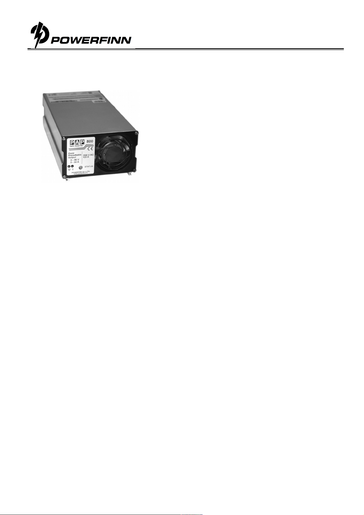
Switched Mode Power Supply
Operating manual PAP800
Perämiehenkatu 6, FIN 24100 Salo, Tel. +358 2
290, Fax +358 2
2918,
[email protected], www.powerfinn.fi
Charging operation
1. Ensure that the power supply is switched off and that the environment meets the conditions as described in
the previous section.
2. Connect the output cables to the load / battery terminals: + cable to the + terminal and – cable to the –
terminal
Note: Do not cut the output cables. In case the cables are shortened, the output voltage is
overcompensated as much as the loss of voltage drops in the cable. The overcompensation may cause
voltage variations depending on the current consumption.
3. Turn the power on by turning the switch to position 1.
4. During normal power supply operation / charging process, the STATUS LED will light continuous orange.
5. To avoid sparking, turn off the power supply before disconnecting the cables.
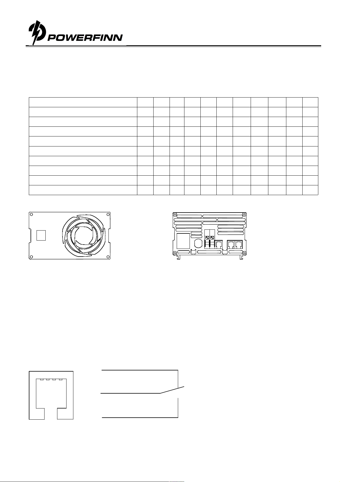
DC Input connection
The power supply input cable is connected as follows:
L negative or positive DC supply input
N positive or negative DC supply input
PE protective earth (required )
The socket outlet shall be installed near the equipment and shall be easily accessible. Maximum 10A maximum
rating of protective device required in building installation. When having unearthed DC mains 2 fuses or 2 pole
circuit breaker required in building installation.
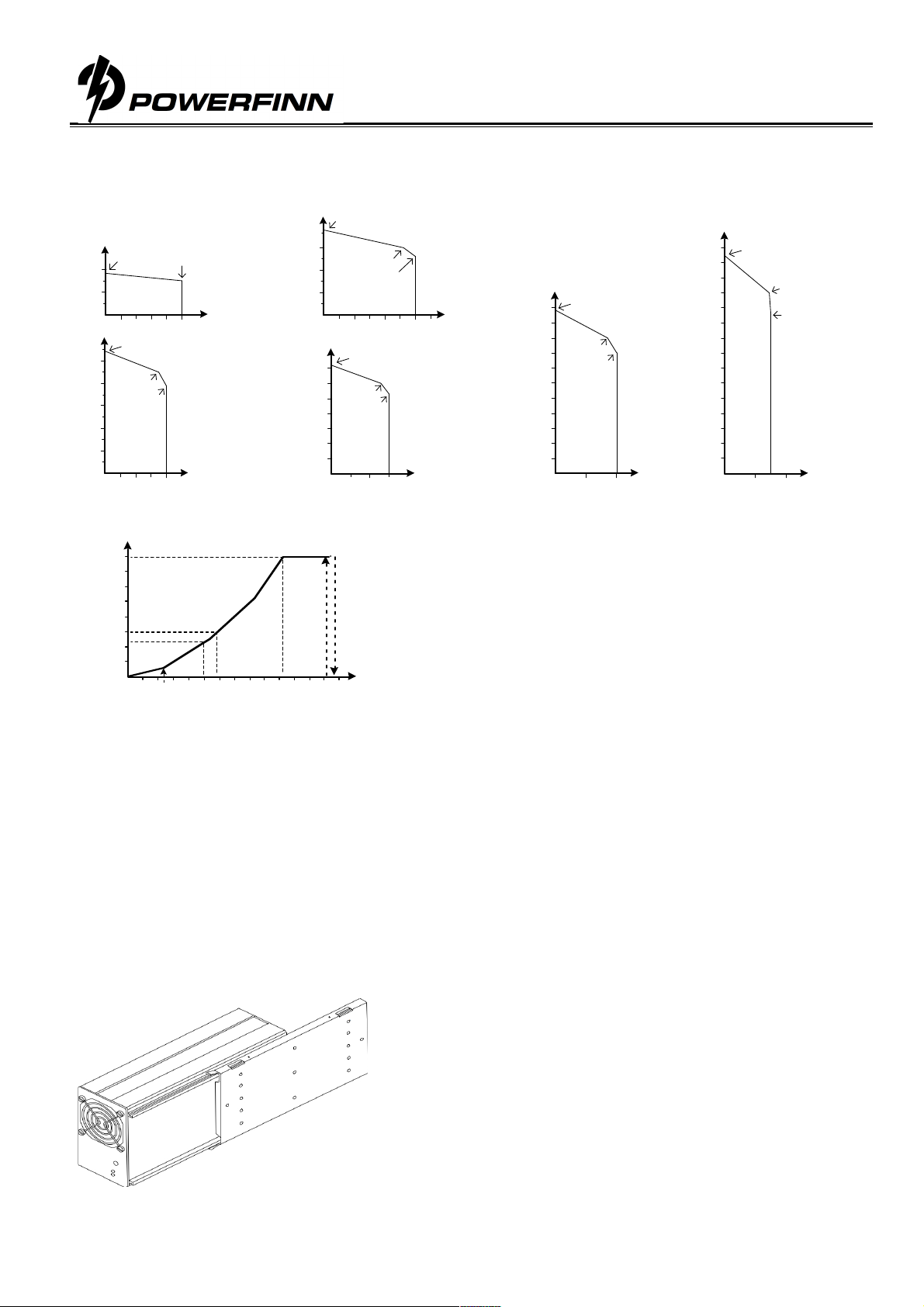
Output voltage and current limit adjustment
Trimmer or analog control adjustable modules, type example PAP800/24 or PAP800/24AI:
The output voltage and output current limit of the power supply can be adjusted as follows:
Trimmer adjustable models: with the multi-turn potentiometers accessible from the front panel.
Analog controllable models by an external 0-5Cdc voltage. See detailed description
Both voltage and current can be adjusted from zero to the maximum value. Maximum 800W output power
is available within the adjustment range.
Temperature compensated models, type example PAP800/24T:
The power supply includes 16 pre-programmed output voltages that are set by the code switch. See the
setting table for this unit. Any of these 16 different voltage settings can be taken in use and additionally be
adjusted within ±5% using the trimmer on the front panel. See the instructions for choosing the
programmed voltage and the fine-tune adjustment.
LED
An orange LED indicates a healthy power supply output voltage.
Overcurrent protection
The output of the power supply is protected against overcurrents and short circuits by an automatic, self-resetting
electronic current limiter.
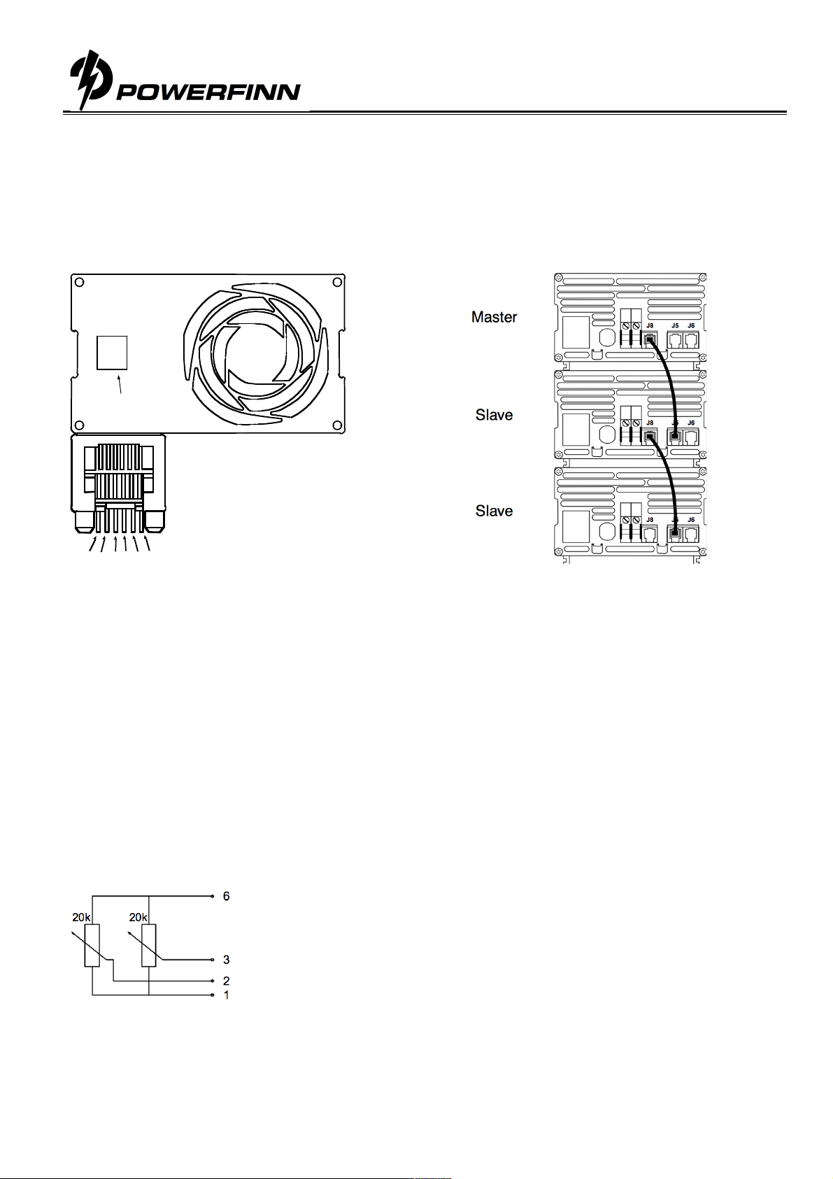
Series/parallel connection
Parallel operation: No restrictions, passive load sharing
Series operation: Up to 500V total voltage
Warning
Dangerous voltages, capable of causing death are present in the power supply. Do not remove the cover. There
are no operator serviceable parts inside the unit. Refer servicing to qualified service personnel only.