PowerFlow 1500 Series User manual

Intelligent Valve Positioner
1500 Series User’s Manual
智能阀门定位器
1500 系列用户手册

Intelligent Valve Positioner 1500 Series User’s Manual
Contents
1 Overview...................................................................................................1
1.1. Product structure..........................................................................1
1.2. Product description and application .............................................2
2. Installation ................................................................................................3
2.1. Mechanical dimensions................................................................3
2.2. Actuator combination ...................................................................5
2.2.1. Actuator of line stroke............................................................5
2.2.2. Actuator of angle stroke.........................................................7
2.3. Interface angle adjustment...........................................................9
3. Connection description........................................................................... 11
4. Technical data.........................................................................................12
4.1. Working data..............................................................................12
4.2. Electrical data.............................................................................12
4.3. Mechanical data.........................................................................12
4.4. Pneumatic data..........................................................................13
5. Operation................................................................................................13
5.1. Interface description...................................................................13
5.2. Operating mode .........................................................................14
5.2.1. Initial mode ..........................................................................14
5.2.2. Automatic mode...................................................................14
5.2.3. Manual mode.......................................................................15
5.3. Function instruction....................................................................15
5.3.1. Auto-tuning ..........................................................................15
5.3.2. Dead band setting................................................................16
5.3.3. Factory setting .....................................................................17
5.3.4. Input signal error detection ..................................................17
5.3.5. Analogue signal output (optional) ........................................17
6. Trouble shooting..................................................................................... 18
7. Attention .................................................................................................18
8. Warranty terms.......................................................................................22
9. Product type selection ............................................................................23

Intelligent Valve Positioner 1500 Series User’s Manual
1
1 Overview
1.1.Product structure
Figure 1. Positioner structure
Protective cover
Electrical connection
Pneumatic connection
Actuator connection
Main body casing

Intelligent Valve Positioner 1500 Series User’s Manual
2
1.2.Product description and application
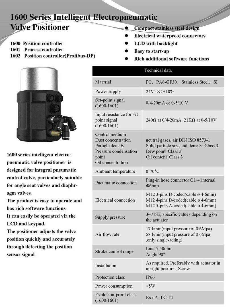
1500 series intelligent valve positioner is a valve stroke controller based on
microprocessor. The valve stroke can be set by external input signal. The
positioner can adjust valve stroke quickly and accurately by using automatic
control algorithm and PWM control technology. The product can be used in
sealed space and controlled automatically and remotely. It is easy to install,
operate, maintain and has low failure rate.
The positioner can combine with different pneumatically actuated valves for
using. As shown in Figure 2.
with diaphragm valve with angle seat valve
Figure 2. Combinations of positioner and pneumatically actuated valves

Intelligent Valve Positioner 1500 Series User’s Manual
3
2.Installation
2.1.Mechanical dimensions
Figure 3. Mechanical dimensions for line stroke

Intelligent Valve Positioner 1500 Series User’s Manual
4
Figure 4. Mechanical dimensions for angle stroke

Intelligent Valve Positioner 1500 Series User’s Manual
5
2.2.Actuator combination
2.2.1. Actuator of line stroke
1. Make sure that the stroke range and the screw thread size of the actuator
which needs to combine meet the requirements.
2. Separately measure the C1 value when the valve is fully closed and C2
value when the valve is fully open by the depth ruler. The values are the
distance between the stem top and the datum clamp face of the actuator.
As shown in Figure 5.
Valve is fully closed Valve is fully open
Figure 5. Actuator measurement
3. Adjust the adjusting nut of the displacement sensor. Then measure the D
value (as shown in Figure 6) by the depth ruler in the state of the
displacement sensor being completely loosened. Calculate the compr-
ession value L1 = D –C1, L2 = D –C2. It is recommended that the
compression value L1 and L2 are both in the reference range which is
showed in Table 1. If L1 value or L2 value is unable to meet the reference
range, adjust the D value according to the actual situation.
Valve
stroke
The datum clamp face
of the actuator

Intelligent Valve Positioner 1500 Series User’s Manual
6
Maximum valve stroke
D range
L1, L2 reference range
5~25 mm
45~51 mm
3~28 mm
25~50 mm
65~71 mm
3.5~53.5 mm
Table 1. The reference range of the compression value
Figure 6. Travel sensor adjustment and measurement
4. Raise the internal valve stem of the actuator to the highest position. Make
the actuator connection of the positioner entering into the thread
connection of the actuator by NO.32 wrench. As shown in Figure 7.
The adjusted D value must ensure that L1 >0, L2 <the maximum
compression value of the displacement sensor. Otherwise, the positioner
cannot match the actuator.
NOTE!

Intelligent Valve Positioner 1500 Series User’s Manual
7
Figure 7. Actuator Combination
5. Power up the positioner, adjust the valve position manually and run the
auto-tuning function in the initial mode. Check that whether the whole valve
stroke range is in the effective range of the displacement sensor (Refer to
the Chapter 5 Section 5.2.1 and Section 5.3.1 for details.). If not, repeat
step 3.
2.2.2. Actuator of angle stroke
1. Fix the mounting body under the positioner. As shown in Figure 8.
2. Connect the feedback pole of the positioner with the axis of the actuator.
As shown in Figure 8.

Intelligent Valve Positioner 1500 Series User’s Manual
8
Figure 8. Graph Installation

Intelligent Valve Positioner 1500 Series User’s Manual
9
Type
H1
H2
L1
L2
PF-1(Default)
20
40
80
100
PF-2
30
50
80/130
100/150
Figure 9. Mechanical dimensions of the mounting body
2.3.Interface angle adjustment
If you need to adjust the interface angle, relax the hexagon screw in place A
(As shown in Figure 7) first. Then adjust the angle clockwise or counter-
clockwise in 180°range. After adjusting the angle, lock the angle by the
hexagon screw.

Intelligent Valve Positioner 1500 Series User’s Manual
10
Figure 10. Graph operation
The positioner has rotation stopper mechanism. If it is restricted to rotate in
one direction, please do not force to rotate continuously.
NOTE!
180°
180°

Intelligent Valve Positioner 1500 Series User’s Manual
11
3.Connection description
Figure 11. Connection
Connection
Pin
Description
Signal Type
X2
1
Analogue signal output +
4 –20 mA
3
Analogue signal output GND
GND
4
NC
NULL
Table 2. Electrical connection description –X2(optional)
Connection
Pin
Description
Signal Type
X3
1
Power supply +
+24 V
2
Power supply GND
GND
3
Set signal input +
4 –20 mA
4
Set signal input GND
GND
Table 3. Electrical connection description –X3

Intelligent Valve Positioner 1500 Series User’s Manual
12
Connection
Description
P
Air supply enter (built-in filter, filter size 20 μm)
R
Air exhaust
C
Check valve
A1
Pilot air outlet 1
A2
Pilot air outlet 2
Table 4. Pneumatic connection description
4.Technical data
4.1. Working data
Ambient temperature: 0~70°C
Protection class: IP66
Vibration resistance parameter: 100Hz
4.2. Electrical data
Connections: cable gland
Supply voltage:
24 V DC ± 10 %, ≥1A. Recommend switching-mode power supply.
Power input: <5W
Input resistance for set-point signal: 120Ω
4.3. Mechanical data
Cover material: Polycarbonate (PC)
Sealing material: Silicone rubber (SI)
Main body material: Polyamide Resin (PA6-GF30)
Error connection of the electrical pin may cause the positioner damage.
NOTE!
The air source pressure bigger than 7 bar may cause positioner damage.
NOTE!

Intelligent Valve Positioner 1500 Series User’s Manual
13
Control stroke range: 5-50 mm
4.4. Pneumatic data
Air pressure range: 3~7 bar, specific values depending on the actuator
Connections: Plug-in hose connector G1/4
Air quality:
ISO 8573-1
Solid particle size and density Class 3
Dew point Class 3
Oil content Class 3
Air flow rate:
17L/min (input pressure of 0.6Mpa)
58L/min (input pressure of 0.6Mpa, only single-acting)
5.Operation
5.1.Interface description
The positioner has a 4-key and 12-led control panel. User can set parameters
and functions by pressing the four keys. 10 blue led lights are used to indicate
the position percent zone of the displacement sensor or the position percent
zone of the valve. They indicate the percent zones of 0-10%, 10-20%, 20-30%,
30-40%, 40-50%, 50-60%, 60-70%, 70-80%, 80-90%, 90-100%. The
“MANUAL” led is used to indicate the operating mode. Led off indicates
automatic mode. Led on indicates manual mode. Led flash indicates initial
mode. “STATUS” led is used to indicate some system running states, such as
system error alarms.

Intelligent Valve Positioner 1500 Series User’s Manual
14
Figure 12. Operating interface
5.2.Operating mode
5.2.1. Initial mode
The positioner is default in the initial mode when it starts up after leaving
factory. In the initial mode, the “MANUAL” led is flash, 10 blue led lights
indicate the position percent zone of the displacement sensor effective stroke.
User can operate keys to open and close the valve. Press key
continuously, the actuator is aerated. Press key continuously, the actuator
is deaerated. Check out and make sure that valve position can move in the
effective range of the displacement sensor and the whole valve stroke range is
in the effective range of the displacement sensor according to 10 blue led and
“STATUS”led.
If the whole valve stroke range is out of the effective range of the displacement
sensor, valve position is held. If the minimum value of the whole valve stroke
range is smaller than the minimum value of the effective range of the
displacement sensor, the “STATUS” led is flash quickly. If the maximum value
of the whole valve stroke range is larger than the maximum value of the
effective range of the displacement sensor, the “STATUS” led is flash slowly.
After system reporting the error, user can’t operate keys.
5.2.2. Automatic mode
After the positioner completes the auto-tuning in the initial mode, system is in
Status light
Mode light
Key 1
Key 2
Key 3
Key 4
Value light

Intelligent Valve Positioner 1500 Series User’s Manual
15
the automatic mode by pressing key to exit. And if the positioner restarts
up, system is default in the automatic mode. In this mode, the positioner
accepts the input signal for set-point value and adjusts the valve stroke
automatically, “MANUAL” led is turned off, 10 blue led lights are used to
indicate the valve position percent zone. The valve is fully close when the
percent of set-point value ≤ 1%, and is fully open when the percent of set-point
value ≥ 99%.
5.2.3. Manual mode
Press key to switch between the automatic mode and the manual mode.
In the manual mode, “MANUAL” led is turned on, 10 blue led lights are used to
indicate the valve position percent zone. User can operate keys to
open and close the valve manually. User also can operate combination keys to
increase the adjustment speed. If after pressing key continuously first,
press key continuously, the valve is quickly open. If after pressing key
continuously first, press key continuously, the valve is quickly close. When
system switches from automatic mode to manual mode or user finishes
adjusting the valve position manually, the percent of current position value is
as the percent of set-point value in the manual mode. The valve is fully close
when the percent of set-point value ≤ 1%, and is fully open when the percent of
set-point value ≥ 99%.
5.3.Function instruction
5.3.1. Auto-tuning
The auto-tuning function can test the related control parameters including the
direction between the aeration state of the actuator and the actual position, the
total valve scale, PWM parameters etc.
Under the any operating mode interface, press key for about 3 seconds to
run the function. During the process of the function running, blue led lights are
scrolling to display the step of the auto-tuning.
After finishing the auto-tuning, all 10 blue led lights are flash. If error appears
during the auto-tuning, “STATUS”led is turned on, and valve position is held.
System will check whether the whole valve stroke range is in the effective
range of the displacement sensor during the auto-tuning process. If the whole
valve stroke range is out of the effective range of the displacement sensor,

Intelligent Valve Positioner 1500 Series User’s Manual
16
valve position is held. If the minimum value of the whole valve stroke range is
smaller than the minimum value of the effective range of the displacement
sensor, the “STATUS” led is flash quickly. If the maximum value of the whole
valve stroke range is larger than the maximum value of the effective range of
the displacement sensor, the “STATUS” led is flash slowly.
During the auto-tuning, the actuator will be detected for air leakage. When the
air leakage of the actuator is detected, the valve position is held, and the
"STATUS" led flashes twice every 2 seconds.
During the auto-tuning, user can press key to exit and turn back to the
previous operating mode.
After finishing the auto-tuning, press key to exit and turn to the specific
operating mode according to the previous operating mode. If the previous
operating mode is automatic mode or manual mode, system turns back to the
previous operating mode. If the previous operating mode is initial mode,
system turns to the automatic mode.
5.3.2. Dead band setting
The function is used to adjust the valve position control accuracy. The system
does not adjust the valve position when the gap between the current position
value and the position set-point value is not bigger than the dead band value.
The minimum value of the dead band is 0.2%, and the maximum value of the
dead band is 5%. Nine blue led lights separately indicate nine dead band
values of 0.2%, 0.4%, 0.6%, 0.8%, 1%, 2%, 3%, 4%, 5% from left to right. In
the automatic mode, press key for about 3 seconds to enter the dead
band setting interface. One led light is flash in order to display the current dead
band value. Press keys to change the dead band value. And the value
is displayed by the blue led flashing. Press key to confirm and exit back to
Although the positioner has ran the auto-tuning function in the factory.
In order to get the control parameters of the actual work environment,
the positioner must run the function again in the actual work
environment.
Make sure that the air supply pressure is in the working range of the
actuator and has no big wave.
Otherwise the auto-tuning may fail or the
test parameters may be error.
NOTE!

Intelligent Valve Positioner 1500 Series User’s Manual
17
automatic mode interface. Press key to exit back to automatic mode
interface without change.
5.3.3. Factory setting
The function is used to recovery the system to factory state. Under the factory
state, the positioner is in the initial mode after starting up, and the dead band
value is the default value 1%. In the automatic mode, press + key for
about 3 seconds to run the function. After finishing the function, system is in
the initial mode. Before matching between the positioner and the actuator,
please make sure that the positioner is in the initial mode after starting up.
5.3.4. Input signal error detection
The function is used to detect the error of 4-20mA input signal. The error
condition is the value of 4-20mA input signal ≤ 3.5mA. Once detecting the error
signal, “STATUS”led is flash. The single-acting power-off safe positioner will
exhaust the actuator cylinder’s air and the single-acting power-off freeze
positioner will keep the valve position and the double-acting positioner will
leave the valve position in a free state.
5.3.5. Analogue signal output (optional)
The positioner outputs 4-20mA analogue signal in the automatic mode and the
manual mode, and dose not output in the initial mode and the running state of
the auto-tuning.
The smaller the dead band setting, the higher the control accuracy getting.
Please set the dead band value in reason. Because the too small value
may cause the solenoid valve in the body to act frequently and lead to long
adjustment time and unstable working state.
NOTE!

Intelligent Valve Positioner 1500 Series User’s Manual
18
6.Trouble shooting
1. LED does not light after the positioner starting up.
Make sure that the 24V DC power supply is normal.
Make sure that the power cables are connected correctly.
2. The positioner is unable to locate position. The valve cannot be fully
opened or fully closed for a long time.
Make sure that the pressure of air supply meets the requirement.
Make sure that the dead band value meets the situation that the valve
position adjustment is stable and has no fluctuation.
Make sure that the pneumatic connections of the positioner and actuator
are not leaking.
7.Attention
1. The power supply voltage of the positioner is 24V DC ±10%. Please check
the power supply before connecting the power cable to the electrical
terminal. Make sure that the power supply is cut off before connecting the
power cable. If the product is damaged by high voltage, it will lose
warranty.
2. Air supply use specification
1> The air pressure should be less than 0.7MPa.
2> Install the filter pressure reducer (5 um filtration accuracy) in front of
the air supply inlet of the positioner to prevent moisture or oil from
infiltrating. In the situation of much oil in the air, it is suggested to
additionally install the oil separator (3 um filtration accuracy) in front of
the air supply inlet of the positioner. It is suggested to use the
combination of SMC brand filter pressure reducer and SMC brand oil
separator. Its model is AC20D-01CG-A. If the product is damaged due
to the oil entering the product without oil separator or filter pressure
reducer being installed, it will lose warranty.
3. After adjustment, the protective cover must be rotated tightly to ensure
IP66 protection class. If the product is damaged by losing the protective
cover or not rotating the protective cover tightly, it will lose warranty.
Table of contents
Other PowerFlow Valve Positioner manuals
Popular Valve Positioner manuals by other brands

Flowserve
Flowserve Logix 3000MD Series Technical bulletin

halstrup-walcher
halstrup-walcher PSW 31 14 Series Original instruction manual

Dresser
Dresser Masoneilan SVI II AP-2 quick start guide

Avid Technology
Avid Technology SmartCal Series Installation and operating instructions

ABB
ABB TZIDC Commissioning instructions

Samson
Samson 3248-1 Mounting and operating instructions

Pepperl+Fuchs
Pepperl+Fuchs PMI360DV-F130-3E2-V15 manual

STI
STI FasTrak Installation and maintenance instruction manual

Balluff
Balluff BIP LD2-T017-04-BP S4 Series user guide

KMC Controls
KMC Controls CMC-1001 installation guide

KSB
KSB SMARTRONIC MA R1310 User instructions

Parker
Parker 404LXR Series product manual