POWERHANDLING PowerHandler A Series Use and care manual

ASSEMBLY, OPERATION, SAFETY
AND MAINTENANCE MANUAL
Manual for All A-Series Models of PowerHandler
Series
A
A25S
A30S
A40S
A60S
* A25S
and A30S are obsolete. Information is For Reference Only

T
TH
HE
E
W
WO
OR
RL
LD
D
L
LE
EA
AD
DE
ER
R
I
IN
N
C
CO
OM
MP
PA
AC
CT
T
M
MA
AT
TE
ER
RI
IA
AL
L
H
HA
AN
ND
DL
LI
IN
NG
G
S
SO
OL
LU
UT
TI
IO
ON
NS
S
2 of 21 Sept/20
TableofContents Page
Cover Page & Table of Contents 2
Instructions upon Receipt of Machine 3
Out of Box Assembly Instructions 4
Air Supply & Line/Connector Requirements 6
General Overview (Rolling Models) 8
A-Series Model Identification (Which Model do you have?) 9
Operation & Safety Manual 10
Handle Shaft Adjustment 10
Maneuvering the PowerHandler (to the Load) 11
Precautions to Take Before Rolling a Load 11
Option: Safety Stop 11
Moving the Load Forward 12
Pulling the Load Backward 12
Trouble Shooting Guide 13
Drive roller turns unengaged, but won’t move the load 13
RPM Test Procedure 15
General Mechanical Maintenance 16
Vane Kit Replacement Procedure –All A-Series 16
Warranty & Guarantee (Machines, Parts, Materials & Labor) 21

T
TH
HE
E
W
WO
OR
RL
LD
D
L
LE
EA
AD
DE
ER
R
I
IN
N
C
CO
OM
MP
PA
AC
CT
T
M
MA
AT
TE
ER
RI
IA
AL
L
H
HA
AN
ND
DL
LI
IN
NG
G
S
SO
OL
LU
UT
TI
IO
ON
NS
S
3 of 21 Sept/20
InstructionsuponReceiptofMachine
Upon receipt, please inspect your box for signs of damage and immediately inform PowerHandling of the
damage.If possible also take digital photos of the damaged box and email them to
sales@powerhandling.com. If there is no physical damage to the outside packaging, place the box on the
ground or work table with the “THIS WAY UP” arrows pointing up and open from the top.
Packaging varies according to the machine, model, etc. In all cases the packaging has been custom designed
to safely and securely protect the machine in transport. Correct packaging is critical in being able to
transport PowerHandlers without damage in transit as the units are extremely dense (very heavy for their
size) and must be securely packed in sturdy packaging that prevents movement of any parts of the machine
within the outer shipping container.
Open the outer and inner boxes to reveal the equipment inside. Ensure all inside boxes have been opened,
as parts are sometimes shipped with machines. Verify all components in the box match the packing slip. If
everything is accounted for, unpack and assemble the machine per the Machine Assembly section of the
manual. If not, contact PowerHandler before continuing.
Please note that damage incurred to a PowerHandler due to incorrect or insufficient packaging is the
responsibility of the sending party. By retaining the original packaging and instructions the unit can be
repacked securely should you need to return the machine at any time for repairs, analysis or upgrade by a
PowerHandling facility.
IMPORTANT NOTE:
ENSURE ALL PACKAGING IS RETAINED
Do not discard packaging. After removal of machine, repack all packaging and instructions into
outer shipping containers and store.By retaining the original packaging and instructions, the unit
can be repacked securely should you need to return the machine at any time for repairs, analysis or
upgrade by a PowerHanding facility.

T
TH
HE
E
W
WO
OR
RL
LD
D
L
LE
EA
AD
DE
ER
R
I
IN
N
C
CO
OM
MP
PA
AC
CT
T
M
MA
AT
TE
ER
RI
IA
AL
L
H
HA
AN
ND
DL
LI
IN
NG
G
S
SO
OL
LU
UT
TI
IO
ON
NS
S
4 of 21 Sept/20
AandT-SeriesOutofBoxAssemblyInstructions
UpperHandleAssembly
◄Step 1
Inspect upper handle tube to ensure it is
smooth and free of damage.
►Step 2
Inspect o-ring installed in the inside diameter of
the lower handle assembly to ensure it is present
and lightly lubricated with a small amount of
grease.
O-RING
◄Step 3
Insert upper handle assembly into lower
handle assembly and adjust to preferred
height and orientation. Tighten clamp
securely.

T
TH
HE
E
W
WO
OR
RL
LD
D
L
LE
EA
AD
DE
ER
R
I
IN
N
C
CO
OM
MP
PA
AC
CT
T
M
MA
AT
TE
ER
RI
IA
AL
L
H
HA
AN
ND
DL
LI
IN
NG
G
S
SO
OL
LU
UT
TI
IO
ON
NS
S
5 of 21 Sept/20
TipPreventer
.
◄Step 1
Remove top bolt on motor side.
►Step 2
Install tip preventer on axle shaft. Install bolt
and spacer into top bolt hole on motor side.
◄Step 3
Install the other side of the tip preventer onto the
opposite axle shaft. Install bolt and spacer into top
bolt hole on non-motor side.

T
TH
HE
E
W
WO
OR
RL
LD
D
L
LE
EA
AD
DE
ER
R
I
IN
N
C
CO
OM
MP
PA
AC
CT
T
M
MA
AT
TE
ER
RI
IA
AL
L
H
HA
AN
ND
DL
LI
IN
NG
G
S
SO
OL
LU
UT
TI
IO
ON
NS
S
6 of 21 Sept/20
AirSupplyandLine/ConnectorRequirements
Generally speaking there is very little maintenance required for your Air-Operated PowerHandler
provided the units are set-up correctly at the outset. Below details the most important items to check in
regard to initial set-up and trouble-shooting, particularly in respect to air supply. For optimal
performance of a PowerHandler, sufficient air supply is essential. The following criteria should be
achieved to ensure sufficient air-flow and performance.
Recommended air pressure and volume
Supplied air pressure should be 6-7 bar (85-100psi) for all models & series of PowerHandler. Above 7 bar
(100 psi) air pressure can damage the vanes of the air motor. The required air volume depends on the
model as larger motors consume more air. See below:
Air Volume: (Litres/min) (Ft3/min)
(44 cfm)
Model
A25S, A30S
A40S, A60S, T40S
1250 lpm
1500 lpm (53 cfm)
In most cases, standard “factory supply air” will accommodate this recommended pressure and flow rate,
however special attention should be paid to air lines and connectors (see below).
Air lines and connectors should not limit air flow / volume
More than 90% of all performance problems users experience with air-operated PowerHandlers are a result
of undersized airlines or connectors.
Additionally, the length of the air line inversely affects air flow and therefore performance. The shorter the air line
the better the performance and a maximum length of 15m (45ft) is recommended for diameters listed in the table
below. If an air line longer than 20m is required, the air lines and connectors should be upsized further. Too
small of a diameter air line (relative to its length) will result in significantly reduced power –evident by both
slower running speeds and less torque.
Please note minimum required internal dimensions of the air lines, connectors and fittings per the table
below:
Model Min. Int. Diameter: Air Line
A25S, A30S
A40S, A60S
12mm (½”)
13-15mm (½”-5/8”)
Connector
12mm (½”)
13-15mm (½”-5/8”)
For safety, an overhead “curly cord” style airline is recommended with the PowerHandler located in its
desired working area. This makes use of the device easier while presenting less of a trip hazard than
having the airlines running across the floor (see photo on next page)
OPTION: SWIVELING AIR LINE CONNECTOR.
PowerHandling offers an inexpensive connector that is sized at
12mm (½”) and swivels 360º for improved maneuverability -
whether the airline is overhead or running down to the floor.

T
TH
HE
E
W
WO
OR
RL
LD
D
L
LE
EA
AD
DE
ER
R
I
IN
N
C
CO
OM
MP
PA
AC
CT
T
M
MA
AT
TE
ER
RI
IA
AL
L
H
HA
AN
ND
DL
LI
IN
NG
G
S
SO
OL
LU
UT
TI
IO
ON
NS
S
7 of 21 Sept/20
The air supply must be clean (i.e. filtered)
Large contaminants in the air supply will clog the screens in the
PowerHandling air valve and at the inlet to the air motor. This
will reduce the air volume delivered to the vanes and result in
reduced torque and speed. Small contaminants in the air
supply will pass through these screens and enter the vanes and
cylinder of the air motor. Some will be immediately exhausted
but others will remain, causing damage and premature wear of
the vanes, bearings and seals along with diminished torque and
speed. If not addressed, the scarring of the inside of the
chamber will require honing of the cylinder or replacement of
the entire motor.
The air supply must be dry (i.e. inline water
traps installed)
Moisture in the compressed air supply will result in corrosion
inside the air motor’s vanes and precipitate the need for
replacement of the vane kit. The effect of moisture will be
diminished torque and speed and ultimately motor failure. A
quick way to check if there is moisture in the air lines is to
remove the muffler and look for moisture and or expelled
corrosion in the muffler.
Lubrication to be provided to the air motor
To maximize the life of your air motor the air supply should be
“continuous oil lubricated”. If this is not available, daily
insertion of a few drops of oil into the air line should be
included in the maintenance procedures of the plant. The
planetary gearbox (gear-sets and bearings) are a sealed unit
and typically will not require any maintenance for the life of
the machine. However, if while maintaining the motor it is
observed the gearbox is not fully packed with grease, please
contact your PowerHandling representative for details on the best course of action.

T
TH
HE
E
W
WO
OR
RL
LD
D
L
LE
EA
AD
DE
ER
R
I
IN
N
C
CO
OM
MP
PA
AC
CT
T
M
MA
AT
TE
ER
RI
IA
AL
L
H
HA
AN
ND
DL
LI
IN
NG
G
S
SO
OL
LU
UT
TI
IO
ON
NS
S
8 of 21 Sept/20
GeneralOverview
PowerHandling’s product line and features are constantly being updated and improved so please check
for more information and updates at www.powerhandling.com.
PowerHandlers are broadly categorized into two types of machines, with an optional third being
a combination of both of these:
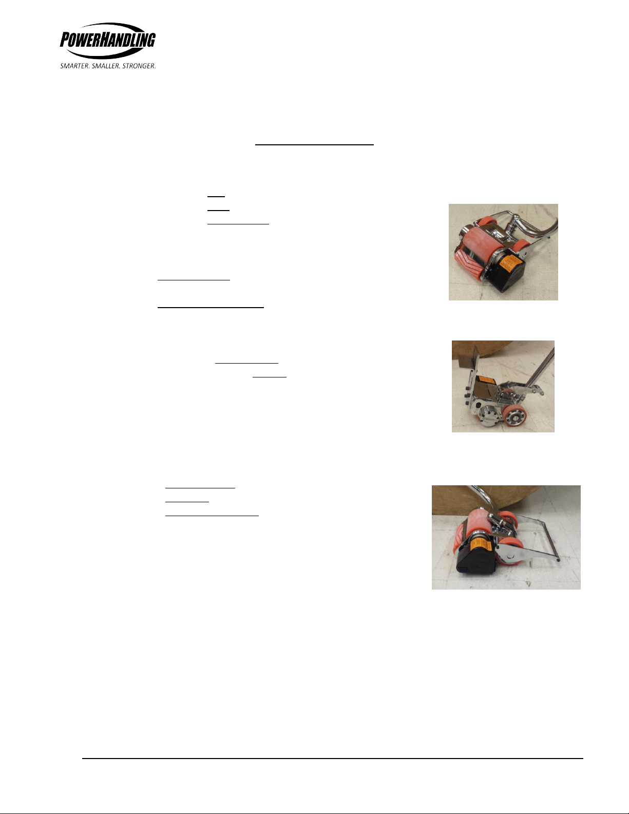
othose that Roll( Fig. 1) (such as paper rolls, cable reels or vehicles) or
othose that Push (such as trolleys, carts etc), or
othose that Roll and Push(Fig. 2) (being a rolling model with a
Hybrid or Pusher Bracket).
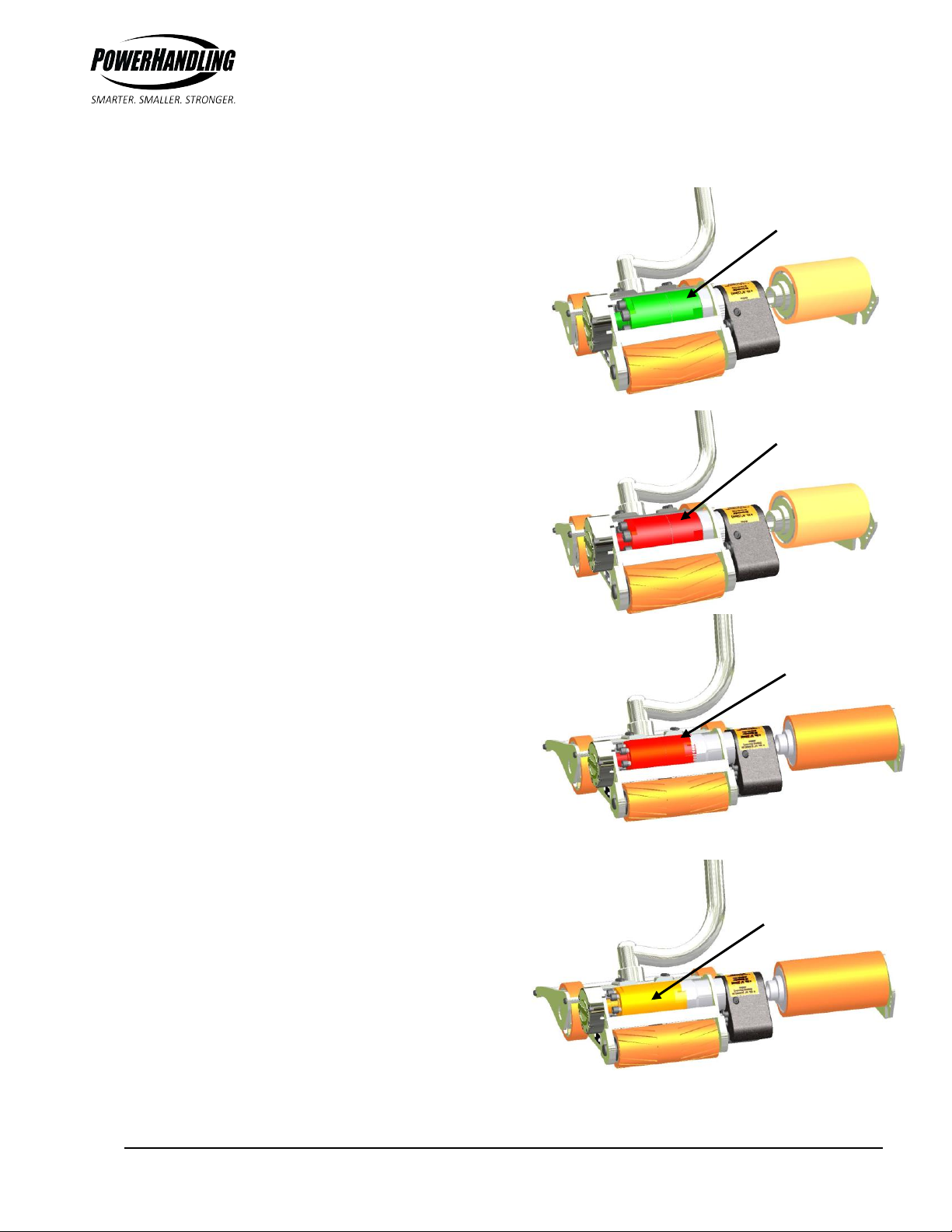
Beyond this distinction there are models powered by:
oCompressed Air –having an airline connected into the back
end of the handle grip throttle; or
oRechargeable Batteries –having two battery packs, one on
the machine and one on a charger (so the machine is never “down” for recharging).
Further model distinctions apply according to:
othe size and power output of the motor, and
othe reduction of the gearing, the latter tailoring a
PowerHandler for higher torque or for higher speed to better
match the requirements of the application. In each case an
increase in one results in a corresponding reduction in the
other.
Finally, models can be further customized according to the handle assemblies and other
attachments, etc. For example ‘Roller’ models can be configured with:
oa Center Straight handle shaft (C), a
oa Swiveling handle shaft (S) or a
oa Swiveling & Pivoting handle shaft (SP)(Fig. 3).
To overcome the inertia of a heavy load, PowerHandlers require a
significant amount of traction –both with the load itself and the ground
on which it’s being moved. Regardless of the amount of power (or
specifically ‘torque’) generated, the load will not move without the
necessary traction.
PowerHandlers gain this traction by directing the weight of the load down onto the drive roller to generate
the traction that is required. In the case of moving cylindrical loads, small diameter / lighter loads can in
fact be more of a problem than larger heavier loads as the weight transfer onto the drive roller is not as
good. This problem will be apparent if the drive roller is observed to slip or spin against the load rather than
wedging in under the load and rotating it. (Please refer to the “Trouble-Shooting” section for suggestions on
how to address this issue).
Fig. 1
Fig. 2
Fig. 3

T
TH
HE
E
W
WO
OR
RL
LD
D
L
LE
EA
AD
DE
ER
R
I
IN
N
C
CO
OM
MP
PA
AC
CT
T
M
MA
AT
TE
ER
RI
IA
AL
L
H
HA
AN
ND
DL
LI
IN
NG
G
S
SO
OL
LU
UT
TI
IO
ON
NS
S
9 of 21 Sept/20
ORANGE GEARBOX
INSIDE
INSIDE
Model Identification (Which Model A-Series do you have?)
The images at right show the four A-Series models with the
drive roller removed to expose the air motors and inline
(color coded) gearboxes
Both the Small A-Series (A25 and A30) and Large A-Series
(A40 and A60) are each available in two versions, with the
only difference being the ratio and torque capacity of the
gearbox.
The lower reduction gearbox (color coded green) is in the
model A25S and provides more speed and less torque.
The higher reduction gearbox (color coded red) is in the
model A30S and A40S and provides more torque and less
speed.
The highest reduction gearbox (color coded orange) is in the
model A60S and provides highest torque and slowest speed.
The difference between the A25 and A30 is about 20% in
respect to performance (both torque and speed) and the
gearbox can be switched out to change to the other model if
this is found to better suit the application.
The difference between the A40 and A60 is about 30% in
respect to performance (both torque and speed) and the
gearbox can be switched out to change to the other model if
this is found to better suit the application
The Large A-Series has a wider body to accommodate the
longer air motor and provide more surface contact for better
grip on larger loads.
The swiveling “S” handle (as shown in the images above) can
be replaced with a straight Centered “C” handle shaft. Other
options available include Hybrid brackets and Pusher
brackets.
A25S
A30S
J30S
A60S
GREEN GEARBOX
INSIDE
RED GEARBOX
INSIDE
RED GEARBOX
INSIDE
A40S
J30S

T
TH
HE
E
W
WO
OR
RL
LD
D
L
LE
EA
AD
DE
ER
R
I
IN
N
C
CO
OM
MP
PA
AC
CT
T
M
MA
AT
TE
ER
RI
IA
AL
L
H
HA
AN
ND
DL
LI
IN
NG
G
S
SO
OL
LU
UT
TI
IO
ON
NS
S
10 of 21 Sept/20
IMPORTANT SAFETY NOTE:
Engaging the throttle with the quick-release clamp still loose
will cause the upper handle shaft to be expelled under
pressure from the lower handle shaft, potentially causing
injury to the operator. Always ensure the quick-release clamp
is tightened securely prior to pulling the throttle.
Figure
1
OperationManual
Handle Shaft Adjustment
The handle shafts of pneumatic PowerHandlers are telescoping, allowing both the height and the
orientation of the handle to be adjusted to suit each individual operator.
1. Release the Quick-Release Clamp at the sliding connection point of the handle shaft.
2. Extend or retract the upper handle shaft according to what is a comfortable working
height for each operator, making allowance for the fact that the unit needs to be tilted
back onto its rear wheels for maneuvering into position.
3. Rotate the handle grip to be pointing to the left, center or right, which will provide
different orientations of the handle grip as the handle shaft
is rotated into each of its four operating positions.
4. If loads are being rolled forwards and only from the
center of the load, the most typical handle orientation
is pointing backwards (position 1 in Figure 2). If the
operator operates the handle with the handle grip
almost always to one side, orient the handle grip to that
side. Figure 2 shows the recommended orientation for
operators using the handle swiveled right.
5. If the unit will be operated with the handle shaft rotated
to both the left and the right sides, we recommend
“motorcycle position” (position 2 in Figure 2).
Each operator may have a different preferred handle grip
orientation. This is easily and quickly adjustable for each
operator at the commencement of the device’s operation.
2
1
Figure 2

T
TH
HE
E
W
WO
OR
RL
LD
D
L
LE
EA
AD
DE
ER
R
I
IN
N
C
CO
OM
MP
PA
AC
CT
T
M
MA
AT
TE
ER
RI
IA
AL
L
H
HA
AN
ND
DL
LI
IN
NG
G
S
SO
OL
LU
UT
TI
IO
ON
NS
S
11 of 21 Sept/20
Maneuvering
To move the machine to the load, take the handle grip in hand
(without depressing the throttle) and tilt the unit back by pushing
down on the handle grip until the front support roller lifts up off the
ground. In this position the device can be easily rolled around on its
rear wheels. When in position to move a load, tilt the unit forward
again so the support roller is down and in contact with the ground
and the drive roller is in contact with the load. Depress the throttle
gradually to smoothly move the load.
Precautions to Take Before Rolling a Load
The PowerHandler should be operated on relatively level and smooth
concrete (or similar) flooring, as is typical for indoor industrial
applications. Operation on sloping (gradient) floors or on uneven
surfaces is a safety risk and not recommended.
Before moving the load, ensure the path over which the load will
travel is not occupied - by either people or obstacles. Also ensure
there is not a slope away from the load which could result in the load
free rolling faster than the PowerHandler. If possible place a “Safety
Stop” on the opposite side of the load to the PowerHandler to ensure
the load cannot move beyond the end of its intended travel.
Operators should refer to the safety procedures of the facility in which the PowerHandler is being used.
All precautions required in ensuring a clear path is available, sufficient warning or safety lock-out is put
into effect and where possible a Safety Stop or similar is in place so as to ensure moving the load will not
result in damage or injury to property or person. Appropriate caution should also be exercised in rolling
loads up inclines due to the risk of the load rolling back onto the operator or other unintended
movement of the load.
OPTION: SAFETY STOP.
PowerHandling offers an inexpensive wedge shaped
safety stop that can be moved to position conveniently
without the operator having to bend down to pick it up
or kick it into position. Its ease of use increases the
likelihood of it being used, increasing operational safety.
The removable handle shaft can be located in either of
two optional locations to suit the requirements of any
paper roll or cable reel stopping application.
HEAVY-DUTY
Wheeled
CHOCK- FOR
CABLE REELS
HEAVY-DUTY
Wheeled
CHOCK- ONLY
FOR PAPER
ROLLS

T
TH
HE
E
W
WO
OR
RL
LD
D
L
LE
EA
AD
DE
ER
R
I
IN
N
C
CO
OM
MP
PA
AC
CT
T
M
MA
AT
TE
ER
RI
IA
AL
L
H
HA
AN
ND
DL
LI
IN
NG
G
S
SO
OL
LU
UT
TI
IO
ON
NS
S
12 of 21 Sept/20
Moving the Load Forward
Once the PowerHandler has been maneuvered into position (just
behind the cable reel, paper roll, wheel or other cylindrical
surface, the operator should lift up on the handle to tilt the unit
forward onto its support roller with the drive roller in contact
with the surface of the load. Then gradually depress the lever of
the variable flow air-valve of the handle grip, accelerating the
load gradually. The further the lever is depressed, the more air
flow to the unit and more speed / torque the unit will generate.
It is generally safest to engage the air flow gradually so as to prevent the possibility of accelerating the
load too rapidly and rolling it beyond the intended travel distance (as a result of the momentum from a
rapid acceleration). This gradual acceleration is also recommended so as to reduce skidding of the drive
roller which can damage either the product being moved or the drive roller. The further the lever is
depressed, the more air flow to the unit and more speed/torque the unit will generate.
Pulling the Load Backward
If your PowerHandler has a pivoting handle system, pulling
backward is not unlike rolling forward. Maneuver your
PowerHandler to either end of the rolling load. Swivel the handle
to the outside of the rolling load and pivot it over the top of the
machine into the pulling position. It is critical that additional
caution is exercised to ensure there are no obstacles to the
operator as they walk backward, pulling the load with them.
Tripping or falling while pulling the load could result in the
operator unintentionally depressing the air-valve lever as they fall, accelerating the load backwards and
onto themselves. To minimize the risk of such circumstance, at a minimum the following additional
precautions should be implemented:
1. The path checked for obstacles or other potential encumbrances to the operator’s travel,
2. The operator walking outboard of the load being rolled backwards, and
3. A Safety Stop to be used to limit the travel of the load.
IMPORTANT SAFETY NOTE:
The PowerHandler does not in itself “control” the load it moves. It rolls the load forwards
but without braking or controlling that movement. Therefore precautions must be taken
to ensure the load does not roll forward further than intended, causing damage or injury
to others. Use of a Safety Stop is one recommended procedure. Note that whatever
method is used, the onus of safety is on the operator to ensure there are no risks involved
with the intended move.

T
TH
HE
E
W
WO
OR
RL
LD
D
L
LE
EA
AD
DE
ER
R
I
IN
N
C
CO
OM
MP
PA
AC
CT
T
M
MA
AT
TE
ER
RI
IA
AL
L
H
HA
AN
ND
DL
LI
IN
NG
G
S
SO
OL
LU
UT
TI
IO
ON
NS
S
13 of 21 Sept/20
TroubleShootingGuide
The Drive Roller turns unengaged but won’t move the load
Determine whether the issue is:
A) TORQUE (drive roller stops turning when engaged with the load) or
B) GRIP or TRACTION (drive roller spins against the load, not moving it),
… and then read the appropriate suggestions for that problem below.
A) TORQUE - The drive roller stops turning when it engages with the
load
This is typically because of insufficient torque being provided to the drive roller and can occur for a
number of reasons.
Check the unloaded rpm of the motor and compare to what it should be (see below). On air
machines power is represented by both torque and speed so an underperforming machine
will turn more slowly, even unloaded.
For additional information on checking the RPM of your machine please see PowerHandling
RPM Test Procedure RPM/RM1.
A25 speed should be 84 rpm.
A30 speed should be 62 rpm.
A40 speed should be 57 rpm.
A60 speed should be 34 rpm.
T40 speed should be 39 rpm.
If the rpm for your model is within 5% of the number shown above the machine should be
performing (i.e. be capable of moving and/or lifting the loads) as per the Data Sheet. If not,
please contact your PowerHandling representative to investigate further.
If the rpm for your model is more than 5% under the number shown above then please
progress through the following trouble-shooting suggestions:
1. The drive roller urethane may have delaminated (i.e. separated) from the drive roll core.
This would give the impression the drive roll is not turning when in fact the core is, but
the polyurethane that should be bonded to it has separated and is not turning with it.
Look at the side of the machine to see if the drive roller core is turning while the
urethane surface is not.
2. The air lines and/or air connectors are not large enough size.
3. The air pressure and/or volume of the air supply are not great enough.
4. The vanes on the motor are blocked by debris or they are too dry.
5. The rotor of the motor has rusted or is otherwise scarred or damaged.

T
TH
HE
E
W
WO
OR
RL
LD
D
L
LE
EA
AD
DE
ER
R
I
IN
N
C
CO
OM
MP
PA
AC
CT
T
M
MA
AT
TE
ER
RI
IA
AL
L
H
HA
AN
ND
DL
LI
IN
NG
G
S
SO
OL
LU
UT
TI
IO
ON
NS
S
14 of 21 Sept/20
6. The muffler/exhaust is not clear, which causes back-pressure. Look for dry oil deposits
or debris in the muffler material that may be inhibiting the exhausting of air. This may
require cleaning and/or if necessary, replacement of the muffler material
7. The sprockets & chains (if applicable) are in poor condition. There’s too much slack in
the chain (stretched chain) or worn/broken sprocket teeth. If parts are damaged,
replace all sprockets & chains together. Do not replace parts separately.
8. The shaft of the motor-gearbox has been damaged (failed key or keyway).
9. There is another mechanical failure or blockage, such as the drive roller is jammed, the
drive chain has broken, a bearing has seized or failed, etc.
B) GRIP - The drive roller spins against the load instead of moving it
This is typically because of insufficient traction between the drive roller and the load being moved and
can occur for a number of reasons, including:
On a brand new machine, there can be a problem with initial grip until the drive roller
becomes “worn in”. This is a temporary condition that can be remedied quickly. The best
way to “wear in” the drive roller is to use it – on loads that do not slip (e.g. larger diameter).
Using it on rolls or other product that does slip will shine up the urethane surface, delaying
the roller wearing in.
The geometry may be accentuating an existing traction problem. Reference the explanation
in the ‘General Overview’ section describing how too small of a diameter load results in less
of the inertial resistance of the load pushing downward (vertical) instead of backward
(horizontal). A small diameter can be moved if there is sufficient friction contact and a large
diameter load can be moved even with very little friction contact, but the combination of a
small diameter and low friction greatly increases the likelihood of slipping. Generally, the
load’s diameter should be > 1000mm (40”).
The drive roller has oil, grease or other low viscosity material embedded into or otherwise
making contact with it, reducing its ability to achieve a friction contact. As the drive roller
makes pressure contact with the support roller while the machine is operating, oil and/or
grease may be picked up from the floor and deposited onto the drive roller in which case the
rollers will need to be cleaned with an appropriate oil dissolving solvent or detergent.
To address low friction issues and reduce the impact of lubricants that end up interfering
with the rollers, the application of Borax (Hydrated Sodium borate –an inexpensive cleaning
agent, ref www.borax.com) to the drive roller can help. All new PowerHandlers and
replacement drive rollers are sent out with Borax already applied.
PowerHandling also offers special low durometer / high grip polyurethane drive rollers for
special applications. These softer rollers will typically not wear as well and so not last as long
at the higher durometer (i.e. harder) polyurethane rollers that PowerHandling provides as
standard.
For more information on servicing your PowerHandler please check the Mechanical
Maintenance Procedures Section.

T
TH
HE
E
W
WO
OR
RL
LD
D
L
LE
EA
AD
DE
ER
R
I
IN
N
C
CO
OM
MP
PA
AC
CT
T
M
MA
AT
TE
ER
RI
IA
AL
L
H
HA
AN
ND
DL
LI
IN
NG
G
S
SO
OL
LU
UT
TI
IO
ON
NS
S
15 of 21 Sept/20
RPMTestProcedure
The first step in troubleshooting most performance problem with a PowerHandler is to check whether the
unit is running at its design speed. This is a quick and simple check to do and requires only a means of
marking the drive roller, a means for counting seconds and about 2 minutes of your time.
Why we want to do this test and why it helps
For pneumatic machines, if insufficient air pressure or volume is being supplied or if there is a mechanical or
other machine problem, it will likely be evidenced by a slower RPM (revolutions per minute). Likewise for
battery-powered machines if the battery is not maintaining the required voltage or other mechanical or
electrical issues exist, the RPM will likely be lower. If a PowerHandler does not appear to roll or lift a load
that it should be able to, the starting point should be “is the machine performing as it should be?”.
Depending on the outcome of this quick test, different paths exist to find the actual solution.
The Test
With the PowerHandler “in situ” – being in the plant and connected to the airline it should operate on (air
machines) or with a fully charged battery pack (battery machines) do the following:
1. Mark the drive roller with the felt tip pen.
2. Pivot the machine back onto its rear wheels, so that the drive roller is out of contact with the
support roller and the support roller is lifted off the ground. (I.e., we want a ‘no-load’ RPM test).
3. Depress the throttle to full/100% speed and the unit has reached its maximum speed, start the
stopwatch as the felt tip mark passes its highest (12 o’clock) position. Then count 10 revolutions and
as the mark again reaches the 12 o’clock position, stop the watch.
4. Immediately repeat above step again and assuming the count is similar, take the average and refer
to the table below to determine the performance of the machine vs. its design speed/RPM.
UNLOADED MACHINE SPEEDS
TYPE MODEL RPM Seconds per 10
Rev's Ft/Min M/Min
AIR
MACHINES
A25 / A30 84 / 62 7.1 / 9.7 72 / 53 22 / 16
A40 / A60 57 / 39 10.5 / 15.4 49 / 34 15 / 10
Interpreting the Results
If the unloaded RPM is within 5% of the values in the table, we consider this acceptable and unlikely to be a
major issue. If it is above 5%, please firstly refer to the trouble-shooting guide in your machine’s Operator
and Maintenance Manual or advise PowerHandling so we can help trouble-shoot the issue. PowerHandling
checks and records the RPM of every machine it builds or repairs (in addition to test running the machine on
a paper roll). This can be used as a comparison to what RPM you measure.

T
TH
HE
E
W
WO
OR
RL
LD
D
L
LE
EA
AD
DE
ER
R
I
IN
N
C
CO
OM
MP
PA
AC
CT
T
M
MA
AT
TE
ER
RI
IA
AL
L
H
HA
AN
ND
DL
LI
IN
NG
G
S
SO
OL
LU
UT
TI
IO
ON
NS
S
16 of 21 Sept/20
AirMotorVaneKitMaintenanceandReplacementProcedures:
◄Figure 1
Using a 5mm Allen wrench,
remove the muffler bolt.
►Figure 2
Gently pry/pull the muffler off the
motor. Some resistance will be felt
due to the integral O-rings.
◄Figure 3
Pull the muffler back until
the air line (Figure 4) is fully
extended.
►Figure 4
Using pliers and a screwdriver or
equivalent, simultaneously press in the
release ring on the air line fitting and pull
the air line out of the fitting.
◄Figure 5
Remove the muffler completely from the air
motor. Note the orientation of the slot in the
motor for later re-assembly.
►Figure 6
Using a 5mm Allen wrench, remove the 6
bolts retaining the bearing housing.

T
TH
HE
E
W
WO
OR
RL
LD
D
L
LE
EA
AD
DE
ER
R
I
IN
N
C
CO
OM
MP
PA
AC
CT
T
M
MA
AT
TE
ER
RI
IA
AL
L
H
HA
AN
ND
DL
LI
IN
NG
G
S
SO
OL
LU
UT
TI
IO
ON
NS
S
17 of 21 Sept/20
◄Figure 7
Remove the bearing housing.
►Figure 8
PowerHandler shown with
bearing housing removed.
◄Figure 9
With a 4mm Allen wrench, remove
the front bolt on the motor side of
the tip preventer.
►Figure 10
Loosen the rear bolt on the motor
side of the tip preventer.
◄Figure 11
Rotate the tip preventer side
plate back.
►Figure 12
Using a 5mm Allen wrench, remove
the muffler retainer bolts.
◄Figure 13
Remove the muffler retainer.

T
TH
HE
E
W
WO
OR
RL
LD
D
L
LE
EA
AD
DE
ER
R
I
IN
N
C
CO
OM
MP
PA
AC
CT
T
M
MA
AT
TE
ER
RI
IA
AL
L
H
HA
AN
ND
DL
LI
IN
NG
G
S
SO
OL
LU
UT
TI
IO
ON
NS
S
18 of 21 Sept/20
◄Figure 14
Using a 5mm Allen wrench, remove
the bolts holding the motor mount
into the machine.
►Figure 15
While supporting the drive roller,
slide the motor mount assembly
out of the PowerHandler.
◄Figure 16
You may need to gently tap the
gearbox from the far side to get it
out of the drive roller.
►Figure 17
Remove the drive roller from the machine and
set aside. If your drive roller is worn, you may
want to replace it as part of your preventative
maintenance cycle.
◄Figure 18
Using a 6mm Allen wrench, remove
the bolts holding the motor and
gearbox in the motor mount.
►Figure 19
Remove the motor mount from
the motor and gearbox.

T
TH
HE
E
W
WO
OR
RL
LD
D
L
LE
EA
AD
DE
ER
R
I
IN
N
C
CO
OM
MP
PA
AC
CT
T
M
MA
AT
TE
ER
RI
IA
AL
L
H
HA
AN
ND
DL
LI
IN
NG
G
S
SO
OL
LU
UT
TI
IO
ON
NS
S
19 of 21 Sept/20
►Figure 21
Unthread the motor from the
gearbox. Please note –this is
a reverse thread.
◄Figure 22
Motor and motor housing shown
removed from the gearbox.
►Figure 23
Remove the motor retention set
screw from the motor housing.
◄Figure 24
Slide the motor out of
the motor housing.
►Figure 25
Motor shown with motor
housing removed.
◄Figure 26
Gently tap the end of the motor
shaft to release the air rotor from
the rotor housing.
◄Figure 20
Motor and gearbox shown with
the motor mount removed.

T
TH
HE
E
W
WO
OR
RL
LD
D
L
LE
EA
AD
DE
ER
R
I
IN
N
C
CO
OM
MP
PA
AC
CT
T
M
MA
AT
TE
ER
RI
IA
AL
L
H
HA
AN
ND
DL
LI
IN
NG
G
S
SO
OL
LU
UT
TI
IO
ON
NS
S
20 of 21 Sept/20
◄Figure 27
The vanes are housed in
slots in the air rotor.
►Figure 28
Remove and replace the vanes.
◄Figure 29
Check the rotor housing for any damage or
grooving that will reduce the life of your vane kit.
Significant roughness on the rotor housing will
require motor replacement.
►Figure 30
When re-assembling the motor,
the shaft end pin is short and the
other end has a long pin.
◄Figure 31
A socket can be used to support the bearing for
tapping/pressing the motor assembly back
together. Verify the motor rotates freely and is
not over-pressed.
►Figure 32
Reassemble the machine in the reverse
order. Care must be taken to align the
motor and gearbox assembly such that the
muffler retention bolt goes in the slot in
the motor housing.
Muffler retention slot
This manual suits for next models
4
Table of contents
Popular Farm Equipment manuals by other brands

Woods
Woods PRECISION SUPER SEEDER Series Operator's manual

Veris
Veris iScan Installation/Removal Guide

enorossi
enorossi 16 Series User and maintenance manual

USC
USC LPX300 Operator's manual

Ziegler
Ziegler CORN CHAMPION S Series Operating and assembly instructions

GREAT PLAINS
GREAT PLAINS Turbo Max 3.0M Assembly manual