Powerlink GXE250-BG User manual

GXE250-BG
OPERATION MANUAL
Biogas Unit
Product No.:1000321484
01-2018
Engine Model:GX13k-LE01G
EN

Biogas Unit
1 Liftingequipment for gensets
WARNING!
Warning! Lifting equipment should be used by trained personnel only. Genset must be lifted
using the lifting lugs on the base frame and a lifting plate or spreader lifting beam.
Preparations before hoisting genset:
When lifting genset, special lifting equipment is required. It is recommended that a lifting
plateor spreader lifting beam of the correct lifting load capacity is used and that chains, hooks,
shackles and eyebolts etc. are checked that they are well within their safe working loads (swl).
The load should be secure, stable and balanced when lifting, therefore an assessment of the
position of its Centre of gravity must be determined to ensure that the lifting point is over it, see
(A, B and C).
Note: When chains are used to lift an engine at an angle, the load on the lifting eye is
increased. An angle of 45° is equal to a 40% increase in load.
The lifting chains etc. must be firmly secured to the load by means of hooks etc. on to the
purpose-designed lifting points, and that the rated included angle is not exceeded.
2 Installation
When install genset the utmost consideration must be given to the type of engine foundation
which must be strong enough to support the weight of the genset and the stresses produced
when the genset is operating.
Undebased/foundation:
The simplest form of mounting is to rigidly bolt and driven the genset directly to an undebased
or bearers. It is essential that all mounting pads on the undebased or bearers are flat, square
and parallel to each other. Undebased or bearers should be designed so that the mounting
pads will not distort in any way and have sufficient rigidity to prevent deflection due to the
weight of the genset, vibrations and various stresses when the genset is running.

Biogas
Type of foundations:
The genset room floor/foundation where the undebased/bearers are fixed is of great
importance as it must:
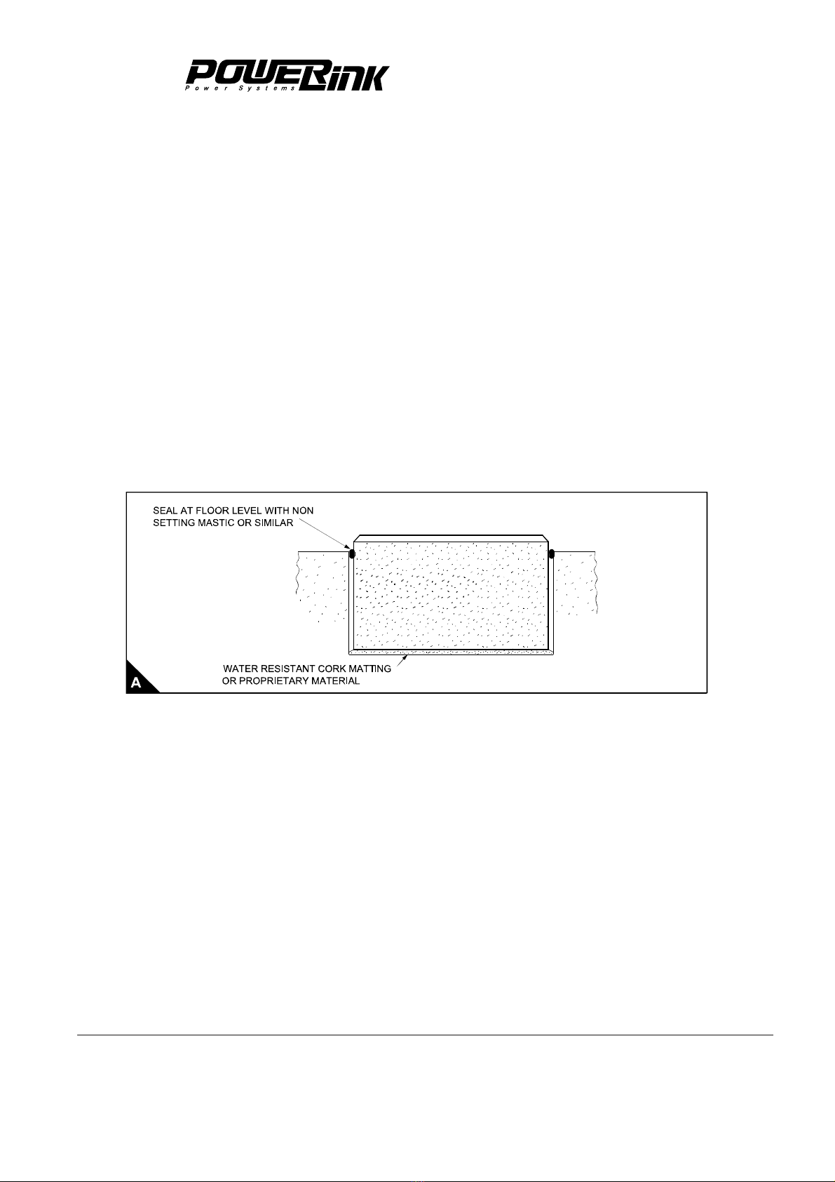
Never use rigid connection between the foundation and genset room.
The surface of the foundation should be oil-water proof, and equipped with drainage
If the genset is set on the floor, the load carrying capacity of floor should be fitted to the static load
and dynamic load of genset.
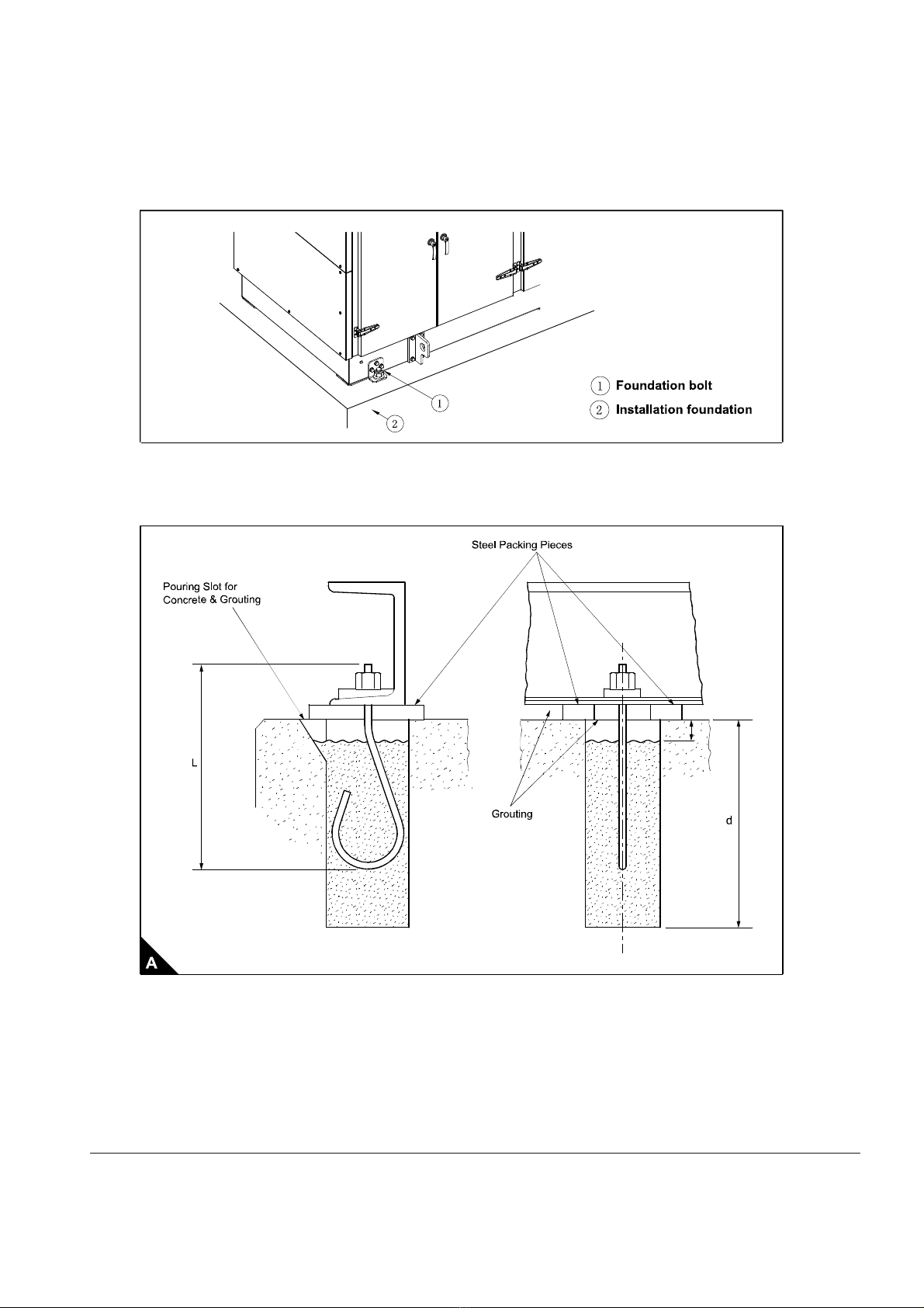
Using shims between the genset mounting feet and the undebased/bearers. The dimensions
of the shims (or packing pieces) should not be less than the mating area of the genset
mounting feet. At least four fitted bolts (minimum quality 8.8 steel) must be used in the genset
mounting feet. Where it is not possible to use a fitted bolt, the mounting feet should be
dowelled to the undebased/bearers using one dowel in each foot at diagonal corners.
The surface of the foundation should be flat. The safe loading capability of the geological
material should be carefully evaluated when selecting the foundation for installing. We advise
adopting concrete as the material of foundation.
SBL=9.81
SB--Weight of the load on the foundation (kg)
TW--Weight of the genset and foundation (kg)
L--Length of the foundation (m)
W—Width of the foundation (m)
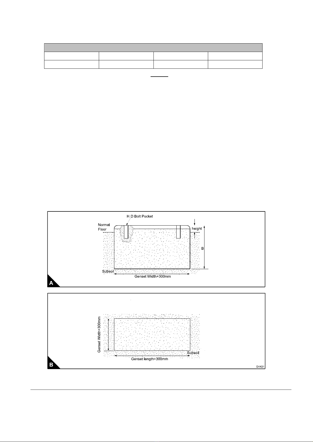
Subsoil-site:
The site subsoil must have a bearing strength capable of supporting the weight of the
complete genset plus the concrete foundation on which it will stand.
If the bearing strength of the subsoil is in doubt advice should be taken from a qualified civil
engineer to enable the type and size of concrete foundations to be determined.
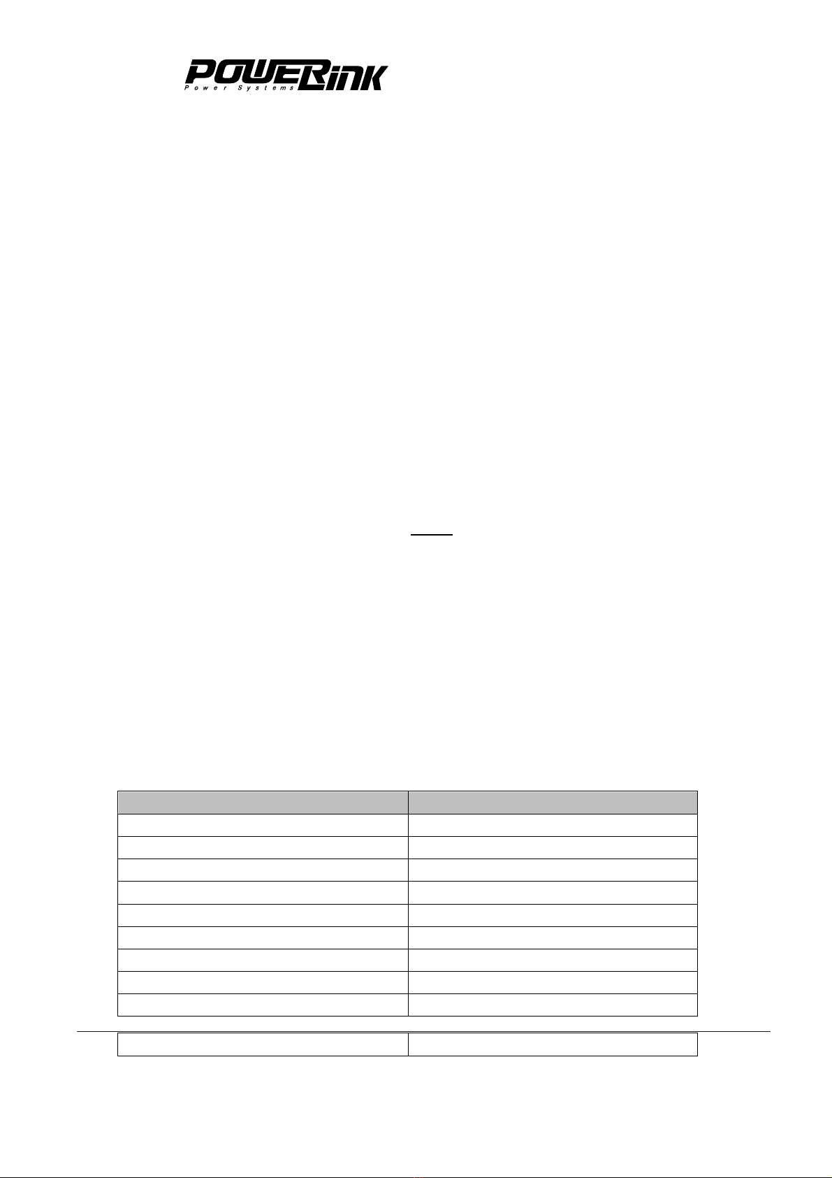
Geological Material Max Load(kg/m²)
Granite 244000-977000
Oil shale 98000-146000
Rock 78000-98000
Soft Rock 49000-98000
Tamped gravel 49000-59000
Pebble and gravel 39000-49000
Tamped sandy clay 28900-39000
Sandy clay 20000-39000
Sand 10000-20000
Soft clay 10000

Biogas Unit
Concrete block/foundation:
Block/Foundation
Length(mm) Width(mm) Depth(m) Height(mm)
Genset Length+300 Genset Width+300 B ≥150
B= 2
B--Depth of foundation (m)
M--Weight of genset (kg)
Ρ--Density of concrete (kg/m³)
L--Length of foundation (m)
W--Width of foundation (m)
After determining the depth of concrete required for the weight and stability of the running
genset, the subsoil has to be checked to see if it will carry the total weight (genset plus
concrete block) and withstand the forces involved.
Fixed concrete block/foundation:
The concrete block/foundation is a proven method and preferred in some circumstances. In
this case the genset set bedplate is tightly bolted to the concrete block. See (A, and B).

Biogas
Floating concrete block/foundation:
The floating block is an effective alternative to the fixed concrete block. The concrete mix,
holding down bolt pockets, surface finish and installation of the set is the same. The block is
pre-cast using a wooden mound.
To isolate and float the block a matting of water resistant cork-like material or similar
proprietary material is placed on the surface of the sub-soil at the bottom of the pit and the
concrete block lowered on to it. The matting should be adequate to support the weight of set
plus concrete block
An air gap of approximately 25 mm should be maintained along all four sides of the block. The
gap at floor level must be sealed with a-non setting mastic or similar material to keep dirt and
water but still allow flexibility, see (A).
All services to the engine, fuel air and water pipes, exhaust system and electric cables must be
fitted with a flexible connection to prevent fractures and possible transmission of harmful
vibrations. Transmission of vibration may culminate as noise at a point remote from the
engine.
Genset Fixation:
The genset mounted on the steel base frame. In order to reduce vibration transmitted to the
foundation while running, the genset is equipped with isolators between the genset and the
base frame.Fix the base frame of the genset with foundation bolts before using the machine.
Each foundation bolts needs to use a hexagonal nut, flat washer and spring washer. The
amount and dimension of foundation bolts should be decided by the installation hole of the
base frame.

Biogas Unit
Check that the bedplate is level without sag or twist. If necessary add shims between the
bedplate and packing plate.Pour and pack the concrete into the bolt hole pockets to within 50
mm of the top. This is to allow for the final grout.
Two typical fixation, see (A and B)

Biogas
Installation procedure for concrete block:
When the concrete block is being poured pockets must be incorporated for the ‘holding down
bolts’ see “Fixed concrete block/foundation (A)”, i.e. See“Two typical fixation (A and B)
hook type or equivalent. At each holding down bolt position removable wooden boxes are
placed. The size of box is to match the size of the bolt used in the installation. When the
concrete is reasonably firm the boxes are removed.
Ensure that the top surface of the concrete block is level and reasonably smooth and free from
blemishes.
Note: After removing the ‘holding down bolt boxes’ leave for 5/7 days to dry out before
positioning the set, see “Two typical fixation (B)” for the method to use the common ‘hook
bolt’.The depth ‘d’ should be a little more than the length of the bolt ‘L’. This is so that the bolt
can be dropped into the hole for the concrete and allow the set to be rolled into position without
obstruction from the bolts.
WARNING!
Use correct lifting equipment. Do not work alone. Always wear protective gear.
When lifting the genset into position it is essential that correct lifting equipment is used having
a tested safe working load well above the weight of the complete set to be lifted. Use the lifting
facilities provided where possible and observe safety precautions regarding suspended loads

Biogas Unit
etc. When the genset is in position pull the bolts up through the holes in the main bedplate. Fit
the washers and nut until approximately a thread length, equivalent, to the nut thickness,
stands proud of the nut.
At each holding down position fit a steel packing plate across the hole and on each side of the
bolt.
Grouting:
The recommended grout mixture is as follows:
Part best quality cement.
2- Parts clean sharp sand.
Grouting mixture is packed into the top of the holding down bolt pockets, around the bolts and
packing pieces, etc., and between the underside flange of the bedplate and the top of the
concrete block, see “Two typical fixation (B).”
Note:Leave for 5/7 days to dry out and set. Check holding bolts and tighten if necessary.
When the set has run for 50/75 hours after the completion of the installation the holding down bolts
should be checked and tightened as necessary.
Trenches:
When designing the foundation block various other areas should be taken into account. Trenches,
particularly for heavy duty electrical cables need to be considered, bearing in mind provision for drainage
to prevent the trench filling up with water.

Biogas
On the larger generating sets these cables have a large bending radius. It may be necessary to cut away
part of the concrete block so that a smooth sweep can be made, see (A).
Concrete raft:
This type of foundation distributes the weight of the genset plus the weight of the concrete raft
over a larger floor area than the fixed concrete block. The unit loading on the subsoil is
minimized and a reduced depth of concrete can be used.

Biogas Unit
3 Summary
A genset consists mainly of power system, lubricating system, gas intake system, heat
exchange system

Biogas
4Genset Structure Overview
Other Powerlink Portable Generator manuals
Popular Portable Generator manuals by other brands

JBM
JBM 53786 instruction manual

Poulan Pro
Poulan Pro PP4300 owner's manual

Ozone Solutions
Ozone Solutions OUV-2800-HF Operation and maintenance instruction

Black Diamond Equipment
Black Diamond Equipment BD201103 Operator's manual

Global
Global MX PrimeGen Service and maintenance manual

Briggs & Stratton
Briggs & Stratton 01655-3 Operator's manual