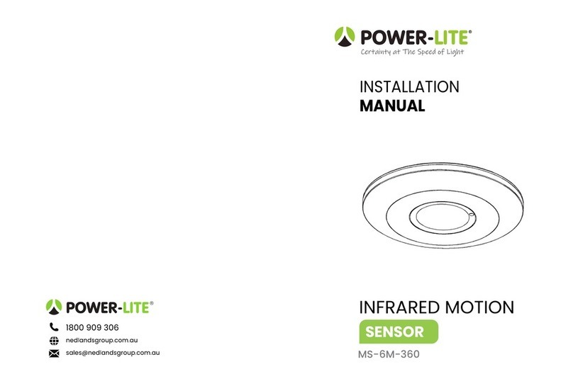
Welcome to using the POWER-LITE Microwave Sensor!
A new saving-energy product; the microwave sensor uses high-frequency electro-magnetic waves
(5.8GHz) and integrated circuit. It gathers automatism,
convenience, safety, saving-energy and practical functions. The wide
detection field depends on detectors. It works by receiving human
motion. When one enters the detection field, it can start the load at once
and automatically identifies day and night. Installation
is very convenient. Detection is possible through doors, panes of glass or thin walls.
Power Sourcing: 220-240V/AC
Power Frequency: 50/60Hz
Ambient Light: <3-2000LUX (adjustable) Time
Delay: Min.10sec±3sec
Max.12min±1min
Rated Load: 2000W max (Incandescent)
Detection Range: 360°
Detection Distance: 16m, adjustable HF
System: 5.8GHz CW radar, ISM band
Transmission Power: <0.2mW Installing
Height: 2-6m
Power Consumption: approx 0.9W
1000W max (Fluorescent & LED) Detection Motion Speed: 0.6-1.5m/s
NOTE: The high-frequency output of the HF sensor is
<0.2Mw- that is just one 5000th of the
transmission power of a mobile phone or the
output of a microwave oven.
Introduction
•Can identify between day time and night time when it is adjusted on the “sun” position
(max). When adjusted on the “3” position (min), it will work under less than 3LUX. As for the
adjustment pattern, please refer to the testing method.
•SENS (sensitivity) adjustable: It can be adjusted according to the location. The detection distance at
low sensitivity can be set to just 2m and high sensitivity of up to 16m, making it suitable for large spaces.
Height-dependent.
•Time-Delay is added continually: When it receives the second induction signal within the first
induction, it will restart to time from the moment.
•Time–Delay is adjustable. It can be set according to the user’s needs. The minimum time is 10sec
±3sec. The maximum is 12min±1min.
Specifications
Function
•Please turn the upper cover anti-clockwise as perthe diagram on the
right.
•Connect the power and the load according to the
connection-wire diagram.
•Fix thebottom on theselected position with theinflated screw.
•Install the upper cover back on the sensor, then you can switch
on the power and test it.
•Turn the TIME knob anti-clockwise on the
minimum (10s). Turn the SENS knob
clockwise on themaximum (+). Turn the
LUX knob clockwise on the maximum
(sun).
•Turn on the power, the light will turn on at
once. After 10sec±3sec later, the light will go out for the first time and then sensing, the load should be
worked.
Thewires come in and
out from the bottom
Thewires come in and
out from the side
16m Detection Distance
Installation
Connection-Wire Diagram
Test


