Powermat Charging Spot 3.1 User manual

Introduction
Installation Guide
Legal Disclaimer
This document contains proprietary and confidential material of Powermat
Technologies Ltd. (“Powermat”). Any unauthorized reproduction, use, or
disclosure of this material, or any part thereof, is strictly prohibited. This
document is solely for the use of Powermat employees and authorized
Powermat customers.
The material furnished in this document is believed to be accurate and
reliable. However, no responsibility is assumed by Powermat for the use of
this document or any material included herein.
Powermat reserves the right to make changes to this document or any
material included herein at any time and without notice.
“Powermat” and the Powermat logo are trademarks of Powermat
Technologies Ltd.
© Copyright 2018 Powermat Technologies Ltd
Confidential © 2018 Powermat Technologies Ltd. All rights reserved
Charging Spot 3.1

Introduction
Table of Contents
1. Introduction
Complementary Documents1.1.
2. Safety, Warnings, Disclaimers
3. Mechanical Schematics and Specifications
Charging Spot Schematics3.1.
Installation Configurations3.2.
Sub-surface vs Surface Mounted3.3.
Charging Spot Specifications3.4.
4. Drilling guidelines
5. Charging Spot Installation
6. Wiring
7. Power Delivery Guidelines
8. TetherBox Installation
9. Final checklist to verify Charging Spots are powered up
10. Network Communication (for Tap to Charge)

Introduction
1. Introduction
This document objective is to help the contractor to install Powermat Wireless
Charging system in the venue.
Complementary Documents1.1.
Before reading this guide, it is recommended to read the below documents
Powermat system components
Store layout guide
Both documents can be downloaded from Powermat sales web page.

Safety, Warnings, Disclaimers
2. Safety, Warnings, Disclaimers
Powermat Charging Spot 3.1 is designed for installation by Powermat certified installers.
Never open or repair the device. It should only be done by an authorized specialist.
Do not install the device under an electrical conductive surface.
Never use the device if it is damaged or wet.
Observe a sufficient distance from warm or wet elements.
Do not use the device outdoors.
Make sure all electrical connections and power supply cables connected are in
accordance with safety guidelines and instruction manual.
Keep all parts out of reach of children.
Never replace damaged power supplies yourself! Disconnect the devices and contact a
specialist.
Compliance with local and regional code
oAll components provided are certified according to rules and regulations
oCompliance with any codes, rules, and regulation as far as wiring, wiring
methods, and techniques lies entirely with the contractor.
oPlease verify with these codes, rules, and regulations before starting any
installation.

Mechanical Schematics and Specifications
3. Mechanical Schematics and Specifications
Charging Spot Schematics3.1.
Installation Configurations3.2.
Powermat’s Charging Spot 3.1 could be installed in either a surface-mounted or a sub-
surface configuration. Due to the required milling accuracy, and necessary permanent
spot marking, Powermat does not endorse on-site sub-surface installations.
Sub-surface vs Surface Mounted3.3.
Surface-Mounted Installation
Sub-surface installation

Mechanical Schematics and Specifications
Charging Spot Specifications3.4.
Parameter
Surface-Mounted
Sub-surface
Hole Profile
Through hole
Partial Cavity
Cavity diameter
2.75” (70mm) Ø
2.75” (70mm) Ø
Top Surface Footprint
Horizontal: 2.9” (74mm) Ø
Vertical: 0.025” (0.65mm) above
surface
Permanent spot position marking
Bottom surface Footprint
Width: 3.83” (97.28mm)
Length: 7.02” (178.31mm)
Thickness: 1.03” (26.16mm)
Width: 3.83” (97.28mm)
Length: 7.02” (178.31mm)
Thickness: 1.03” (26.16mm)
Drill Tools
TCT, bi metal, or diamond grit
hole saw
Hand tool ok (if used with jig)
CNC / routing –shop only
Surface Material
Wood/MDF/ply, Corian, stone
surfaces
Wood/MDF/ply, Corian, stone
surfaces
Substrate*
No substrate ok
No substrate ok
Minimum Thickness
0.5” (12.7mm)
0.5” (12.7mm)(to be verified)
Maximum Thickness
3”
3”
Drilling guidelines
4. Drilling guidelines
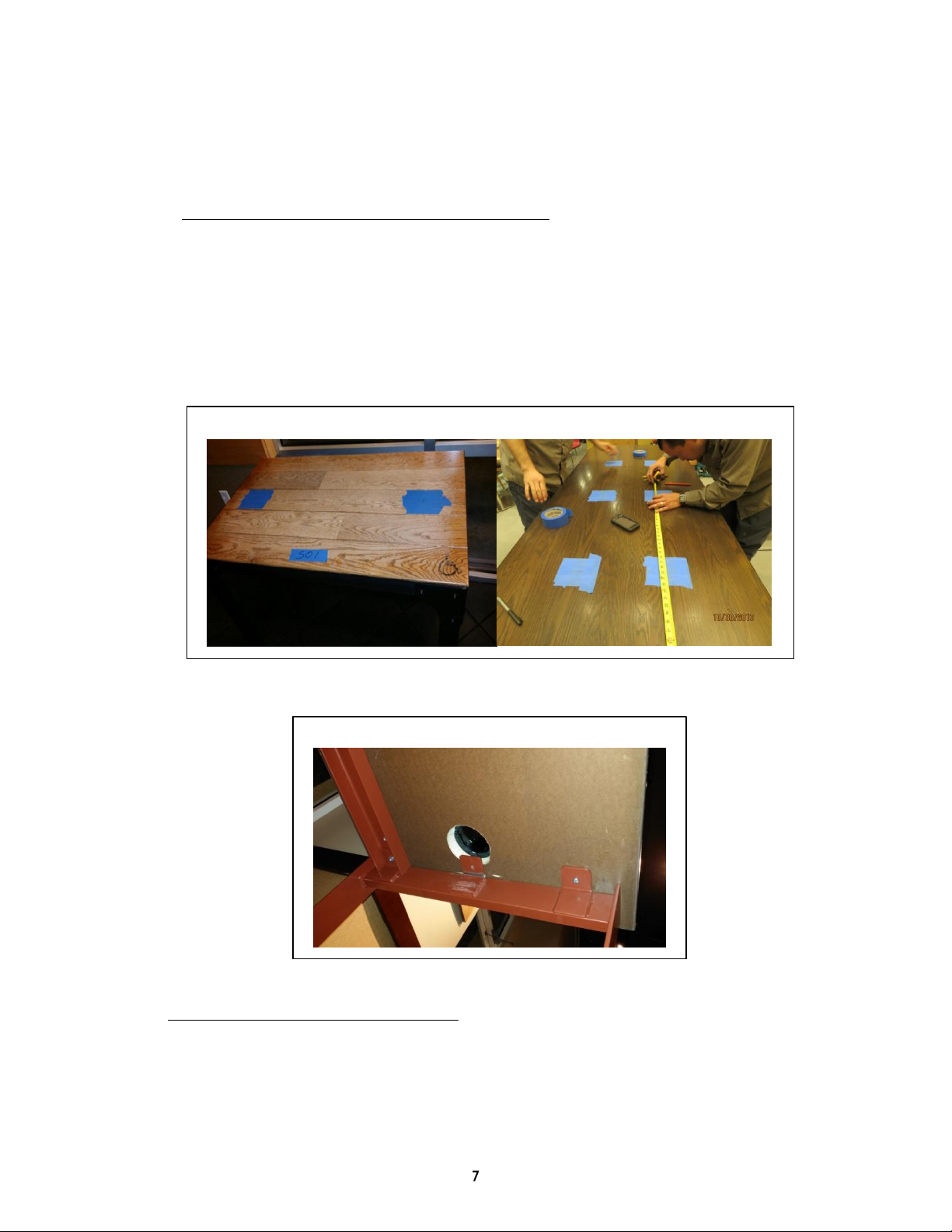
1. Step 1 - mark the spots locations on the table
1. Make sure it’s according to the quantity requested per table
2. Mark all the locations before drilling and make sure all are aligned vertically and
horizontally
3. Make sure not to mark a place above a leg or a bracket
4. When marking the drill locations use painters tape, this will prevent surface
chipping while drilling see Figure 1: Marking the Charging Spots location
Figure 1: Marking the Charging Spots location
Figure 2: Drilling over a bracket
2. Step 2 - Verify again table thickness
The charging spot can be installed in tables between ¾” to 3” (19.05 mm – 76.2 mm)

Drilling guidelines
3. Step 3 –Drilling
General guidelines:
a. Drilling can be done with a hand tool
b. Make sure the hole saw is facing exactly 90 degrees to the surface
c. It is recommended to use a bit as part of the hole saw
d. Make sure drilling area is covered with painters tape to avoid surface chipping
see Figure 1
NOTE: After drilling, make sure to clean burrs and splinters around top ream in order
to ensure proper fit.
NOTE: Charging Spot requires a wooden substrate underneath any stone surface
Table 1: Drilling Requirements Surface Mounted
Drilling Requirement
Value
Hole Profile
Through hole
Hole Diameter
2.75” (70mm) Ø
Drilling Tool
On-site Drilling:
Bi metal hole saw 2.75” / 70mm
Diamond grit hole saw–to be used with a proper
jig
*for on-site hand tools, masking of the hole with
painters tape and the use of a pilot bit is recommended
Off-Site Drilling:
TCT hole saw –with shop bench-press
CNC/ router –shop only
Diamond grit hole saw–to be used with a proper
jig
Table 2: Drill Type Selection
Important note: Charging Spot requires a wooden substrate underneath any stone surface
Figure 3: Hole saw with a drill bit
Surface Materials
Drill types
Wood and wood composites
All drills can be used
Corian
All drills can be used with the exception
diamond grit hole saw
Quartz and Granite
Diamond grit hole saw only

Drilling guidelines
Table 3: Drilling Requirements Sub-surface
Drilling Requirement
Value
Hole Profile
Partial Cavity
Cavity Diameter
2.75” (70mm) Ø
Thickness of surface
above cavity
0.14" (3.5mm)
Drilling Tool
On-site Drilling:
NA
Off-Site Drilling:
CNC/ router –shop only

Charging Spot Installation
5. Charging Spot Installation
In order to power the Charging Spots, they should be connected to a power source.
The system works on a safe DC power, which is converted from the AC power outlet
in the wall by a power adaptor.
1. Charging Spot Kit –Components:
Table 4: Charging Spot Kit components list
Installation Hardware
A. 4 x #6 3/8” screws
B. 4 x #6 1” screws
C. 4 x screw plugs
Charging Spot Assembly Parts
D. 1 x surface-mounted cap
E. 1 x silicone gasket
F. Magnetic module sub-assembly
G. Electronics module sub-assembly
H. Charging Spot Housing
I. 1 x centering spacer ring (for Sub-
surface assembly only)
Table of contents
Other Powermat Batteries Charger manuals

Powermat
Powermat 2X User manual

Powermat
Powermat PMR-NOK1-EU User manual

Powermat
Powermat 2X User manual

Powermat
Powermat 2X User manual

Powermat
Powermat Home & Office Mat User manual

Powermat
Powermat Home & Office Mat User manual

Powermat
Powermat Charging Spot 4.0 User manual

Powermat
Powermat Powermat Wireless Charging User manual

Powermat
Powermat Receiver Back for Nintendo DSi User manual

Powermat
Powermat Powermat Wireless Charging User manual


