Powerohm Resistors PK series User manual

PowerOhm Installation Manual
for “PK” Series
Braking Modules
IMPORTANT: These instructions should be read thoroughly before installation.
All warnings and
precautions should be observed for both personal safety and
for proper equipment performance and longevity. Failure to follow these
instructions could result in equipment failure and/or serious injury to
personnel. Braking modules contain lethal voltages
when connected to the
inverter. It is very important to remove power to the inverter before installing
or servicing this unit. Always allow adequate time (approximately 5 minutes)
after removing power before touching any components. The POWER ON LED
must be completely out and the resistor elements cool before servicing the unit

2 a brand of ICD, Inc.
•Page 2: Table of Contents for Manual HCPMAN0013_R1 (2015-03-31)
•Page 3: Product Overview and Inspection
•Page 4: Environmental Conditions and Electrical Ratings
•Page 5: Equipment Installation
•Page 6: Dimensions and Weight for PKx005 and PKx010
•Page 7: Dimensions and Weight for PKx050
•Page 8: Wire Recommendations
•Page 9: Wire Sizing
•Page 10: Power Connections for PKx005 and PKx010
•Page 11: Power Connections for PKx050
•Page 12: Control Connections
•Page 13: Module Set Up - Jumper Descriptions and Locations
•Page 14: Module Set Up – Factory Jumper Settings
•Page 15: Module Set Up – Voltage Selection and Master/Slave Jumpers
•Page 16: System Integration - Drive DC Bus Connections
•Page 17: System Integration - Single Module Power Connections
•Page 18: System Integration - Master / Slave Power Connections
•Page 19: System Integration - Master / Slave Control Connections
•Page 20: Start Up
•Page 21: Start Up
•Page 22: Troubleshooting
•Page 23: Troubleshooting
•Page 24: Troubleshooting
•Page 25: Troubleshooting
•Page 26: Notes
•Page 27: Notes
•Page 28: Last Page
Table of Contents

3 a brand of ICD, Inc.
AC variable frequency drives are commonly used with various types of motors to
form reliable variable speed drive systems. Problems with these drive systems can
occur when an application requires a deceleration rate faster than what can be
managed by the drive alone, or when motor speeds exceed the synchronous speed
set by the output frequency of the drive (which is called an overhauling load
condition). Both of these conditions create regenerated power which flows from the
motor back into the drive, causing its DC Bus to rise. To manage the regenerated
power and avoid shutting the drive down due to an over-voltage trip, this power must
be dissipated by an external braking resistor.
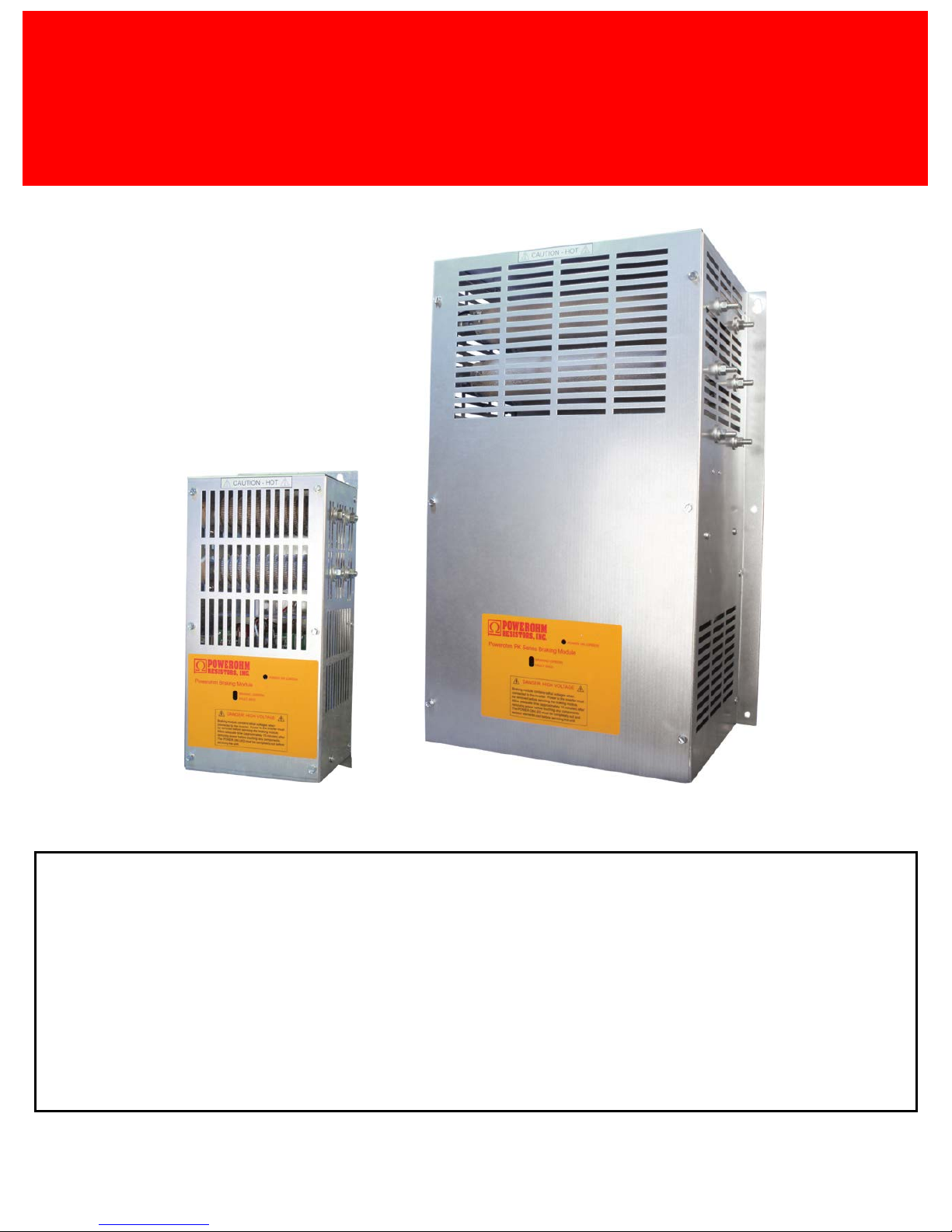
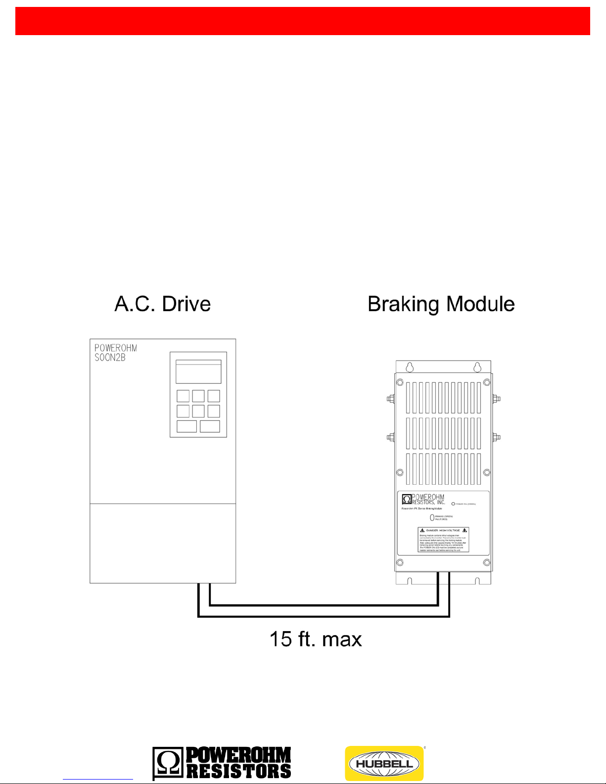
PowerOhm Braking Modules can be used in conjunction with any AC drive to
monitor the DC bus of the drive and activate an internal braking resistor as
needed not only to avoid over-voltage trips, but to greatly improve the performance
of the drive system.
The products covered in this manual are intended to be used with Listed inverter
drives. The input of the DBU is only to be connected across the DC bus of the
inverter drives. Conductors for connection of the DBU shall be according to the
NFPA 70 (National Electric Code) and the drive instructions.
Inspection upon Receipt
Upon receipt of your PowerOhm Braking Module, be sure to carefully unpack the module and
inspect the unit carefully for any shipping damage. The module contains electronics that can be
damaged by static electricity, so handle in accordance with industry standards. Check for loose,
broken or otherwise damaged parts due to shipping. Report any shipping damage immediately
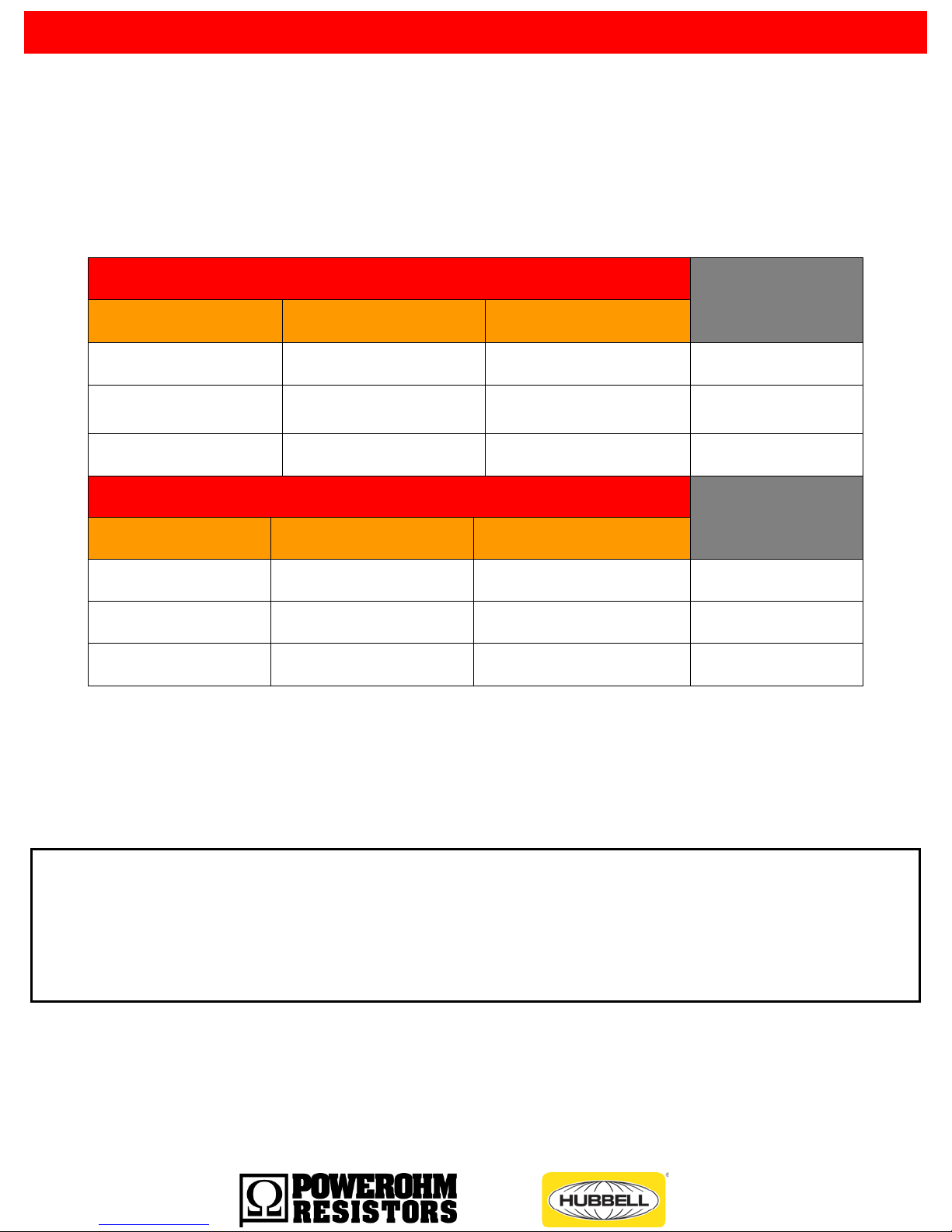
to the freight carrier. Be sure to verify that the part number and ratings listed on the nameplate
match the order specification and the capabilities of the drive system.
The ratings listed on the nameplate are critical – installing and energizing the incorrect
part number could damage the braking module and/or the drive!
Product Overview

4 a brand of ICD, Inc.
The PowerOhm PK Series Braking Module should be installed in an environment protected
from moisture and excessive dust. Dust buildup can reduce the electrical insulation
characteristics of the unit and moisture can cause arching or shorting. Air must be free of
combustible gases and corrosive vapors.
Enclosure: Type 1
Ambient Temperature Range: -10ºC to 40ºC
Maximum Altitude: 3300 feet (1000m)
Maximum Vibration: 10 to 20Hz, 32ft/sec/sec; 20 to 50Hz, 6.5 ft/sec/sec
Electrical Ratings
The PowerOhm PK series Braking Modules have their own internal braking resistors making
installation simpler. They are available in three different voltage classes including 240, 480 and
600 volts. Maximum Ratings are shown in Table 1.
TABLE 1: General Specifications for Series PK Braking Modules
ROCKWELL
Part No. AC Line
Voltage
Res
Value in
Ohms
Turn ON
Voltage
Continuous
Wattage
Capability
% Cont
Duty
Cycle
Internal
Fuse Rating
HCPPKA005
240
28
375vdc
667
11.8
FWP70-10
HCPPKA010
240
13.2
375vdc
1650
10.3
FWP70-15
HCPPKB005
480
108
750vdc
1500
19.8
FWP70-10
HCPPKB010
480
52.7
750vdc
2063
11.1
FWP70-15
HCPPKB050
480
10.5
750vdc
8000
8.7
FWP70-40
HCPPKC005
600
160
940vdc
1500
16.8
FWP70-10
HCPPKC010
600
80
940vdc
2063
10.1
FWP70-15
HCPPKC050
600
15.8
940vdc
8000
8.4
FWP70-40
Fusing is closely coordinated with the PowerOhm Crowbar circuits. ONLY 700vdc rated
FWP, A70QS, or equivalent semiconductor fuses should be used.
•Custom turn on voltage’s are notshown in this manual
Environmental Conditions

5 a brand of ICD, Inc.
Equipment Installation
The PowerOhm PK series Braking Module should be installed on a low vibration surface that is
non-flammable.
Check for physical damage and for loose wires or plugs after installation.
Attention: Installation and removal of this equipment should be done by
qualified personnel
only. Equipment must be installed in accordance
with all applicable national and local electrical codes and regulations.
MOUNTING REQUIREMENTS
To allow proper cooling, it is very important to install convection cooled PowerOhm braking
modules in the vertical position (see Figure 1). A convection cooled model is simply a unit
withouta factory installed cooling fan.
Braking modules should have at least 6 inches clearance on all sides to allow for adequate
cooling. More distance may be required to keep brake module heat from affecting nearby
components. Interconnecting wiring should not exceed 5 feet between modules.
FIGURE 1: Mounting Position for Convection Cooled Modules

6 a brand of ICD, Inc.
Dimensions and Weight
The PowerOhm PK series Braking Modules shown below in Figure 2a and Figure 2b includes
the dimensions of both units
FIGURE 2a: Braking Module Dimensions for Part Numbers
PKA005, PKA010, PKB005, PKB010, PKC005 and PKC010
Weight: The weight is approximately 14 lbs.

7 a brand of ICD, Inc.
FIGURE 2b: Braking Module Dimensions for Part Numbers
PKB050 & PKC050.
Weight: The weight is approximately 45 lbs.

8 a brand of ICD, Inc.
Wiring Recommendations
It is recommended that the AC drive manual and braking module instructions and any other
pertinent documentation be thoroughly reviewed before proceeding. Note that control and
power wiring should be separated to avoid electrical noise and interference problems. The
wiring between the drive and braking module should not exceed 15 feet.
Use CU conductorsonly with insulation rated for 75° C minimum or equivalent.
Important: Always properly ground each component to Power Earth ground (PE). Ground
Brake Module DIRECTLY to AC Drive Module Power ground, and ensure the drive cabinet
has a good ground.
FIGURE 3: Wiring Lengths Between Drive System Components

9 a brand of ICD, Inc.
Wire Sizing
Reference Table 2 for suggested minimum wire sizes only. Keep in mind the duty cycle rating
greatly affects the minimum wire size needed.
TABLE 2:Wire Sizing for Power Interconnections
3
Motor HP at 10% Duty Cycle
WIRE
SIZE
240VAC 480VAC 600VAC
1HP to 50HP
1HP to 75HP 1HP to 75HP 10 AWG
60HP to 100HP
100HP to 150HP
100HP to 150HP 8 AWG
N/A
200HP-250HP
200HP-250HP 6AWG
Motor HP at 30% Duty Cycle
WIRE
SIZE
240VAC 480VAC 600VAC
1HP to 30HP 1HP to 40HP 1HP to 40HP 8 AWG
40HP to 75HP 50HP to 75HP 50HP to 75HP 6 AWG
100HP 100HP to 250HP 100HP to 250HP 4 AWG
Note: 18 AWG wire is sufficient for all control and signal wiring.
ATTENTION: The National Electric Code (NEC) and local regulations
govern the installation and wiring of electrical equipment such as braking
resistors and modules. DC power wiring, AC power wiring, control wiring
and conduit must be installed
in accordance with all applicable codes
and regulations.

10 a brand of ICD, Inc.
Power Connections
Wire Sizing
The PowerOhm PK series Braking Module features a total of 2 power connections and an
earth ground Terminal location and size is dependent on the current capacity of the model. See
reference tables 3a,and 3b for a description of each terminal’s function, torque, type of
connection and wire size.
TABLE 3a: Description of Power Connections for PKx005 and PKx010
Terminal
Designation Terminal
Description
Maximum
Torque
(lb-in)
Connection
Type Tool
Required Maximum
Wire Size
1 DC Bus Negative 20 #6 spade lug #2 Phillips 10 awg
2 N/A N/A N/A N/A N/A
3 N/A N/A N/A N/A N/A
4 DC Bus Positive 20 #6 spade lug #2 Phillips 10 awg
Power Earth
Ground
15 #10 Ring Lug 5/16” socket 10 awg
Power Terminals at bottom of module with cover removed

11 a brand of ICD, Inc.
TABLE 3b: Description of Power Connections for PKx050
Terminal
Designation Terminal
Description
Maximum
Torque
(lb-in)
Connection
Type Tool
Required Maximum
Wire Size
DC -DC Bus Negative 72 5/16” ring lug #2 Phillips 4 awg
DC + DC Bus Positive 72 5/16” ring lug #2 Phillips 4 awg
Power Earth
Ground
15 #10 Ring Lug 5/16” socket 6 awg
Power Terminals at bottom of module with cover removed
Field wiring to studs must be made by a UL listed clamp or closed-loop terminal
connector sized for the wire gauge involved.

12 a brand of ICD, Inc.
Control Connections
The PowerOhm PK series Braking Module features a 10-position terminal block for all signal
and control wiring. All terminations on the block can accept bare wire or fork lugs for a #6 screw.
Reference Table 4 for a description of each terminal.
TABLE 4: Description of Control Connections for All PK Models
Terminal
Number Terminal Description Electrical Ratings Maximum
Torque
(lb-in)
1
Slave Input Pulse (Positive)
24vdc @ 10ma
7
2 Slave Input Pulse (Negative) 24vdc @ 10ma 7
3 Fault Contact Output (NO or NC) 125vac/24vdc @ .5a 7
4 Fault Contact Output (NO or NC) 125vac/24vdc @ .5a 7
5 Master Output Pulse (Positive) 24vdc @ 50ma 7
6 Master Output Pulse i (Negative) 24vdc @ 50ma 7
7 Non-functioning termination N/A 7
8 Non-functioning termination N/A 7
9 120VAC external Enable & Fan .5a @ 125vac 7
10 120VAC external Enable & Fan .5a @ 125vac 7
Note: 18 AWG wire is sufficient for all control and signal wiring

13 a brand of ICD, Inc.
Module Setup
The PowerOhm PK series Braking Module has several jumper settings that are accessible on
the main circuit board. The front cover has to be removed to change the jumper settings.
Warning: Do not make jumper changes while power is applied! Change as required only after
power is removed and the green power indicator is off! Use insulated tools when changing
jumper positions. TABLE 5: Description of Jumper Settings
Jumpers
Jumper Description
JP1-JP5
Set to match the actual on site AC line voltage
JP6
Selects Internal or ExternalBrake Enable
JP7
Selects a Master or Slave configuration
JP8
Selects a NC orNO Fault contact.
FIGURE 4a: Control Board Jumper Locations

14 a brand of ICD, Inc.
FIGURE 4b: Control Board Jumper Positions
Brake Enable Jumper: JP6 selects between internal enable or external enable modes
Internal (Automatic): When the JP6 jumper is in the downward position, the Brake is
Enabled automatically wheneversystem DC Bus voltage is applied.
External: When the JP6 jumper is in the upward position, the Brake is Enabled ONLY
when voltage is applied to control terminals 9 and 10. This position is recommended
so the Brake can be disabled when the drive is not running.
•The PKx050 REQUIRES voltage at terminals 9 & 10 to run the cooling fan so JP6
MUST be set to external for brake module to be enabled.
TABLE 6: Factory Installed Enable Jumper Settings
PowerOhm
Part No. Line
Voltages
JP6
Brake
Enable
JP7
Master
Slave
JP8
Fault
Contact
PKx-005
200-600
Internal
Master NCPKx-010 Internal
PKx-050 External
CAUTION: Do not make jumper changes while power is applied! Change
as required only when power is removed and the green power indicator
is off! Use insulated tools when changing jumper positions.
CAUTION: If the braking module is not disabled when the drive is idle
the DC bus voltage can reach a value high enough to turn on the braking
module, potentially causing the braking resistor to over-heat.

15 a brand of ICD, Inc.
Line Voltage Level Jumpers: The voltage ID box in fig 4a indicates the voltage class, which
determines the DC threshold level for each jumper position. PK series braking modules are
calibrated to the DC voltages shown in the JP4 column in table 7, with JP4 ON. Moving the
jumper to another position changes the DC turn on thresholds as shown in table 7.
TABLE 7: DC Voltage turn on voltages for PK models
Voltage Class JP1 JP2 JP3 JP4 JP5
200vac 323vdc 339vdc 355vdc 375vdc 391vdc
400vac 646vdc 677vdc 709vdc 750vdc 782vdc
600vac 813vdc 853vdc 892vdc 940vdc 980vdc
If the actual drive input AC Line voltage differs from the factory default setting considerably,
and the external enable command is not used, it may be necessary to change the jumper
setting to match the power source.
•Generally speaking, it is best to operate the module with the highest allowable setting
to allow forupward drift of the AC line & DC bus during unloaded conditions
•Drive over-voltage trip leveland reactions to bus rise must be taken into account
•Removing the enable forces the brake to ignore any over-voltage conditions when the
drive is not running
For PK Models the factory setting of JP4 should not be changed unless an extremely high
DC bus is seen or expected,and the external enable command is notused.
Master - Slave Jumper: When the JP7 jumper is in the upward position, the braking module is
in the Slave mode. If the JP7 jumper is in the downward position, the braking module is in
the Master mode. When a single module is used it must be in the Master mode. If multiple
modules are needed, only one unit can be in the Master mode while all other modules are in
the Slave mode.
Fault Contact Jumper: When the module is operating properly and JP8 is in the upward
position the fault contact is Normally Closed (NC). When JP8 is in the downward position the
fault contact is Normally Open (NO). Contacts change state only during a fault condition and
do not change state when the module is powered ON or OFF. If equipped with the standard
crowbar circuitry and the IGBT fails, the fuse will be purposefully blown and the fault contact
will never reset.

16 a brand of ICD, Inc.
System Integration
FIGURE 5: Drive DC BUS Power Connections
Internal/External Chopper: In the example above, the internal and external chopper
connections are shown. Both should never be used at the same time. An external
chopper is needed when a drives internal chopper cannot support the desired duty
cycle, or when the drive has no internal chopper transistor.
Wiring Notes: All DC power wiring should be connected DIRECTLY to the DC bus caps
of the drive as shown in Figure 5. Connecting upstream of contactor or line chokes
may cause an overvoltage or high frequency switching condition and possible damage
the brake and drive.

17 a brand of ICD, Inc.
FIGURE 6: Power Connections for a Single Braking Module
Master - Slave Jumper Settings: In the example above, the braking module is set as
the Master(JP7 is the downward position).
Wiring Notes: All DC power wiring between the drive and braking module should be
twisted (if possible) and run separate from allcontrol wiring.

18 a brand of ICD, Inc.
FIGURE 7: Power Connections for Multiple Braking Modules
Master - Slave Jumper Settings: In the example above, the top braking module is set
as the Master (JP7 is the downward position) and the lower module is in Slave Mode
(JP7 is in the upward position).
•Damage may occur ifboth jumpers are set for master with signal wires connected
Wiring Notes: All Power wiring should be twisted (if possible) and run separate from all
control wiring.

19 a brand of ICD, Inc.
FIGURE 8: Control Connections for Multiple Braking Modules
Master - Slave Jumper Settings: In the example above, the left braking module is set
as the Master (JP7 is the downward position) and the right module is in Slave Mode
(JP7 is in the upward position).
•Damage may occur ifboth jumpers are set for master with signal wires connected
Wiring Notes: All Control wiring between the drive, braking module and braking resistor
must be twisted and run separate from all Power wiring.

20 a brand of ICD, Inc.
Start Up
PRELIMINARY:
•Ensure the DC bus connections are properpolarity.
•Make sure that braking module voltage rating is equivalent to the drive and that all
voltage selection jumpers are in the proper positions.
•Ensure the drives internal braking is disabled.
•Ensure the enable jumper is set according to your application. JP6 is Factory set for
an external enable voltage at control board terminals 9 & 10 for the PKx-050.
THE BRAKE MODULE WILL NOT TURN ON IF THE MODULE IS NOT ENABLED.
•To see the internal LEDs it will be necessary to position yourself directly in front of the
module front cover looking into the cover viewing hole.
•It is good practice to monitor the DC bus under stopped and braking conditions,
making sure the braking setpoint is not too close to the nominal unloaded DC bus
voltage.
•In order to best capture the peak voltage use an oscilloscope or voltmeter with a peak
hold function.
POWER UP: As the DC bus pre-charges the green POWER ON LED illuminates indicating that
DC bus voltage is properly applied to the DC- and DC+ power connections. At this time the
braking and fault LEDs should be OFF. Note unloaded DC bus level.
BRAKING CYCLE: Start the drive and run the motor unloaded. Stop the drive quickly and
monitor the green BRAKE LED. The LED will flash on, the heavier the braking, the more it
flashes. Load motor, then start and stop drive and again monitor braking LED. Note DC bus
level during the peak of the braking cycle. If the unloaded nominal DC bus is within 10% of the
peak DC Bus during braking consider increasing the braking voltage threshold or using a drive
contact to disable the brake while drive is idle.
DECELERATION: While under full load slowly decrease drive decel time while monitoring DC
bus level. Decrease decel time as process allows until DC bus rises near the drive high bus
trip level. Now increase decel time back to a level allowing a comfortable amount of headroom
to prevent nuisance overvoltage trips. (If the drive trips on overvoltage easily or you can’t stop
the drive fast enough, the brake module may be undersized)
This manual suits for next models
8
Table of contents