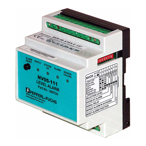
PowerTech PT-1090 User manual

PT-1090
USER MANUAL


Wiring Diagram
Power supply
The power supply is DC15V/2.5A switching power
a.Use 12VDC, 7Ah sealed lead-acid battery, and replace it every 3-5 years.
b.A standard system with a keyboard power consumption of 180mA can support 24
hours.
c.When using without siren, connect a 2.2K resistor to clear the siren fault.
d.The total power supply demand of the keyboard, auxiliary power supply, siren, etc.
does not exceed the maximum power of the host.
e.The maximum charging current of the battery is 350mA.
f.When using wired/bus defense zones, you need to set the defense zone attributes
in the defense zone attribute settings.
Warning: Please insert SIM card before installation, then power on.
BELL
PBUS
A RLY B
+ 12V - A-ZONE-B A-KEY-B + 12V - Z1 COM Z2 Z3 COM Z4 + 12V - Z5 COM Z6 Z7 COM Z8 TAMPER
PGM
Keypad
Siren Single bus interface
Relay
module
Aux power
output
2.2K
2.2K
N.O.
NO
2.2K
NC
N. C.
2.2K
NC
DC15V/2.5A
SIM Card
+ -
POWER WAN LAN2 LAN4LAN1 LAN3 WPS/
RESET
Batt
EGND
SIM
SIM
L E D FL A S H
Card 1
Card 2
Speaker
interface
Pickup
interface
PGM
4G 2G
Mic
+ -
Bus
module

Wired Siren Wiring Instructions
+
+
+
¾ u ¥
¾ u ¥
° ¥ h
° ¥ h
ÏÐÝ-
ÏÐÝ+
î ‚ w- ùŒ5˜Ú =K
° à5· ˜¾ · 5 à Œù
+
+
ÏÐÝ-
- kk+
- kk-
Ð.Ðh
Ê ÛØáê ÜåÜáÚê ÜçÛê ÜåØ×æÜåØáŸ
ãßØÔæØåØÙØåçâç ÛØÙâßßâê ÜáÚÖâááØÖçÜâáà ØçÛâ×-
- kk¹
- kk- ùŒ5˜Ú =K
Siren
Siren
FàÒS5·˜Ï J
FàÒS5·˜ÐJ
¿âêßØéØßÔßÔåàÖ âááØÖçÜâá
Ê ÛØáç ÛØÜáãèçéâßçÔÚØâ ÙçÛØÍ ÂÁ¸ç Øåà ÜáÔß
ÙÔßßæÕØßâê¤ ÉŸÔáÔ ßÔåàê ÜßßÕØçåÜÚÚØåØ×
¨ · °
ùŒ©õ

Z1 ) 53 @ @ ) 53 @ @ ) 53 @ @ ) 53 @ +-4*
Z 08 Expansion Module Description
+12V
GND
B
A
ON
1 2 3 4
Power Indicator
Zone status indicator
Wiring instructions
DIP switch
+12V
GND
B1
A1
Light
Power indicator: always on when power is on;
Zone status indicator: Zone is enabled and flashes slowly when normal
When the zone is faulty, it always lights up.
Dialing code description
Please dial the code according to the table below.
DIP SW# Zone#
Keypad#
1
2
3
4
5
6
7
1111
0111
1011
0011
1101
0101
1001
41~48
49~56
57~64
65~72
73~80
81~88
89~96
DIP SW# Zone#
Keypad#


Content
Foreword 1
Features 2
Led instruction of network alarm platform 2
Insert SIM card 2
Panel led instruction 3
Insert SIM card 3
Remote phone control 4
Take alarm call from alarm panel 4
GSM SMS remote control 5
FC-7602 Dual Zone Expansion Module 5
keypad instructions 7
Wiring instructions 7
Keyboard address setting 7
Function button 8
Led lights 8
Common operation 9
Public zone 11
Duress password 12
Arm/disarm alarm panel 13
Alarm procedure 14
System maintenance 15
Programmable output 16
I. System setting 17
1. Set sys password 17
1.1 Set admin pwd 17
1.2 Set main user code 18
1.3 Set user code 18
2. Set system network 18
2.1 Set DHCP 18
2.2 Set IP 19
2.3 Set gateway 19
2.4 Set subnet mask 20
2.5 Set DNS 20
3. Set CMS 20
3.1 Phone ala center 20
3.1.1 Set CMS line 1 21

3.1.2 Set CMS line 2 21
3.1.3 Set account 21
3.1.4 Enter dial times 21
3.2 Network CMS 22
3.2.1 Set server IP 22
3.2.2 Set server port 22
3.2.3 Set CMS account 22
3.3 SIA platform 23
4. Set voice phone 23
4.1 Voice phone 23
4.2 Phone dial times 23
5. Set SYS options 24
5.1 System time 24
5.2 Entry delay 25
5.3 Exit delay 25
5.4 Bell time 25
5.5 Force arm 26
5.6 Emergency tone 26
5.7 AC power off delay 26
5.8 Door sensor check 27
5.9 WLS sensor loss 27
5.10 Voice prompt 27
6. Set wireless 28
6.1 Set remote 28
6.1.1 Enroll remote 28
6.1.2 Enter remote code 28
6.1.3 Delete remote 29
6.2 Set WLS detector 29
6.2.1 Enroll detector 30
6.2.2 Enter code 30
6.2.3 Delete detector 31
6.3 Set WLS siren 31
6.3.1 Enroll siren 31
6.3.2 Delete siren 32
6.4 RF switch 32
6.4.1 Enroll switch 33
6.4.2 Enter switch code 33
6.4.3 Delete switch 33
7.S et system zone 34

7.1 Set zone type 35
7.2 Set zone siren 36
7.3 Doorbell tone set 36
7.4 Keyboard zone 37
8. Set system area 38
8.1 Password area 38
8.2 Keypad area 39
8.3 Remote area 39
8.4 Zone area 39
8.5 Voice phone area 40
8.6 Slect partition 40
9.S et other 41
9.1 Wired zone 41
9.2 Relay 42
9.3 SIM card set 42
9.3.1 SIM default set 43
9.3.2 SIM card 1 set 43
9.3.3 SIM card 2 set 43
9.4 Timing arm/disarm 44
9.5 Single bus device 44
9.5.1 Device status 45
9.5.2 Device info 45
9.5.3 Device opttion 45
9.5.4 Device restart 46
9.5.5 Restore to fact. 46
9.6 Keypad fault disp 47
10.Advanced set 48
II. WEB IE setting 50
1. Access to the host 50
2. Basic management 51
2.1 System Kanban 51
2.2 System management 52
2.3 Wireless device 53
2.4 Single bus device 54
2.5 Smart control 54
2.6 Scene management 54
2.7 Other settings 56
2.7.1 Wired zone settings 56

2.7.2 Bypass group setting 57
2.7.3 Relay settings 57
2.7.4 Keyboard area settings 57
2.7.5 Keyboard fault display 58
2.8 System log 58
3. Network settings 59
3.1 TCP/IP settings 59
3.2 GPRS settings 60
3.3 Email settings 60
3.4 CMS platform 61
3.5 SIA platform 62
3.6 PSTN alarm platform settings 64
4. System options 64
4.1 Alarm parameter settings 64
4.2 Alert settings 66
4.3 Password settings 67
4 4 Voice call settings 68
4.5 Timing Arm/Disarm 69
5. System maintenance 70
5.1 System information 70
5.2 Time settings 70
5.3 System restart 71
5.4 System backup 72
5.5 System restore 72
5.6 System upgrade 73
5.7 Reset device 73
III. App use 74
1. Download and installation 74
2. Account registration 74
3. Add panel 75
4. Camera binding host 75
5. Add other accessories 76
Technical specifications 77
System maintenance 77
Product function limitation 78

User manual
Congratulations on your obtaining a set of reliable and multi-functional security
products that have been tempered and passed a variety of certifications.
PT-1090 is an intelligent anti-theft alarm control panel that integrates anti-theft, fire
prevention and gas leakage prevention, and is compatible with wired and wireless alarm
methods. Remote operation through the Internet, mobile phone APP, CMS, etc. greatly
facilitates the user's control of security information.
The PT-1090 also uses the most advanced international BUS zone coding technology
and multi-digit random code hopping technology in terms of safety and reliability, which
effectively avoids the interference and false alarms that are difficult to solve by the current
similar systems. The PT-1090 supports the international SIA-2013 network GPRS in the
alarm signal transmission mode, and also adopts the high-speed Contact ID format
commonly used in the world, which makes the system more widely used and more
compatible. This system can be widely used in family districts, villas, shops, enterprises and
institutions and so on. In order to better use this product, please read this manual before
use.
This manual has been checked in detail by the technicians, such as product upgrades
and changes without notice.
Foreword
Warning:
A.Do not disassemble or modify, otherwise it may cause danger and cause damage to
the machine.
B.Do not put other objects into the machine. Metal objects, water and flammable
objects are all prone to short circuit or fire.
C.To avoid injury, do not drop the machine or subject it to strong impact.
D.Do not install the machine near a magnetic field, it may cause unstable operation.
E.Keep dry and clean. Do not set it in a place with oily smoke or steam, high
temperature or a lot of dust.
F.Avoid high temperatures. Please do not install the unit near a heater or other high-
temperature equipment, such as near a spotlight; also do not place it in a place that is
easily exposed to direct sunlight, otherwise it may cause color fading. When cleaning,
please wipe with a soft cloth. To remove dirt, you need to use detergent solution. Wipe
after wringing out.
G.Never use chemicals such as gasoline or paint thinner, otherwise it may cause
damage or paint peeling.
1

Features
User manual
§ Can be divided into 4 independent areas, with 32 wireless zones, 8 wired
zones, 56 expansion zones can be expanded by bus port (including 24
keyboard expansion zones and 32 bus zones), 32 single-bus zones, total
support 128 zones.
§ The device has 1 web administrator account, 1 system administrator
password, 1 main user, and 32 ordinary users.In addition to the system
administrator password, other accounts can log in to the web page to access
the host.
§ Support 8 remote controls, 4 two-way wireless siren, 8 keyboards, 32
appliance switches.
§ Support 2 network alarm receiving platforms and 2 telephone alarm
receiving platforms, which can be set to backup mode and dual alarm mode
§ Support 4 voice phones to send voice and text messages
§ Support mobile APP remote control and alarm information push
§ Timing arm and disarm: 4 groups of timing arm and disarm time, you can
assign any one or several partitions to be effective.
▲Two SIM cards can be inserted, and the priority SIM card can be set.
LED ON——Network is normal
Fast flashing——network failure
Flash once per second——connected 1 platform via network
Flash twice per second——connected 2 platforms via network
Flash once in 3 seconds——connected 1 platform via GPRS
Flash twice in 3 seconds——connected 2 platforms via GPRS
Led instruction of network alarm platform
2

User manual
Panel led instruction
Arm and disarm status LED: Area 1, LED is always ON when armed, LED
is OFF when disarmed, flash once every second when stay armed
Alarm LED:Area 1, flashes when alarming, LED always ON when zone
fault, LED flashes once per second when AC or battery fault
Network LED: LED is always ON when the network is normal, LED is OFF
when the network is fault, and LED falshes quickly when the network is
connected to the platform.
GSM status LED: LED flashes once in 3 seconds when GSM is normal, LED
flashes once in 1 second when GSM is fault , and LED flashes quickly when
GPRS connects to the platform.
Insert SIM card: The telephone card is Micro SIM .
SIM card
holder
A. Push backwards the
lid and pull up.
B. Insert the SIM card .
45451
23466
44566
59798
45451
23466
44566
59798
C. Cover the lid well.
3

You will hear:
Enter password
3
DK~DK~
The alarm panel take the phone call
after finish 7 times ringing(factory
default is 7 times)
2
User call the phone #
of the alarm panel
Remote phone control
Pls enter the user password 1234
(factory default)
123
Take alarm call from alarm panel
4
User manual
Press 1 to arm area
Press 2 to disarm area
Press 3 to stay area
Press 4 to check area status
Press 7 to enable the intercom
Press 8 to listen in
Press 0 to hang up
The alarm panel will call the user when alarm happens. see below diagram.
Door sensor send
alarm signal
Alarm panel make
alarm call
User pick up the
alarm call
You will hear below voice guidance
on the phone call.
Press 1 to cancel alarm
Press 2 to inquiry alarm event
Press 3 to arm area
Press 4 to disarm area
Press 5 to stay area
Press 6 to enable siren
Press 7 to disable siren
Press 8 to live monitoring
Press 9 to PGM control
Press 0 to hang up
1
4

GSM SMS remote control
Arm command:
Enter the sms command on phone #PASSWORD:1234#ARMED AREA X
Disarm command:
Enter the sms command on phone #PASSWORD:1234#DISARM AREA X
Stay arm command:
Enter the sms command on phone #PASSWORD:1234#STAY AREA X
User manual
Note: X is the area #, from 1 to 4. Default use password 1234(no space). You will
receive a reply sms message if the panel accept and proceed your SMS command.
FC-7602 Dual Zone Expansion Module
64 32 16 8 4 2 1
1 2 3 4 5 6 7 8
ON
41+(32+8)→{
Area 1:81
Area 2:82
The starting zone number of the PT-1090 mainframe extended zone is 41.
DIP code example:
→Representative value
→Switch serial number
64 32 16 8 4 2 1
1 2 3 4 5 6 7 8
ON
41+(32+8+2)→{
Areavç
Areavç
→Representative value
→Switch serial number
5
The black square " ■ " is the position of the dial.
1.PT-1090 is a dial-code address code dual-zone module, and the end resistance
of the connected line is 10K.
2. The extended address range of the module is 41~96, and the defense zone
type is disabled by default. When using it, the corresponding defense zone
should be enabled.
3. Wiring method: red wire (DC+), black wire (GND), yellow wire (RS487A),

User manual
6
white wire (RS487B), green wire (NC1), black wire (GND), blue wire (NC2).
4. Operating voltage range: DC8.5~24V.
5. The 1st bit of the DIP switch is the tamper detection switch, ON turns on the
tamper detection, OFF means the tamper detection off; 2~8 are the address
bits, ON is valid, OFF is invalid, the address calculation method is binary, For
example, the address of defense zone 1 is 81: the dial code of positions 3 and
5 needs to be dialed to the ON position, and the address of zone 2 is 82.
The set defense area 1 address is the dial code value + 41, and the defense
area 2 address is the defense area 1 address + 1.

After accessing the new keyboard, the keyboard shows that no address has been
set. Please press and hold for three seconds when disarmed and in the
standby state to enter the keyboard address setting. Up to 8 keyboards can be
added. For example: add keyboard as address 07.
ENTER DEVICE ADDR vç 70
(00--16)
LCD display
User manual
LCD
LED
Touch keys
) URQWYLHZ 5HDUYLHZ
Terminals
1 2 3 4
ON
DIP switch
Wiring instructions
Please follow the wiring diagram below to connect.
Host
connection
port
Touch keyboard connection port
˜›–Š••¢1Œ•˜œŽ• ˜›–Š••¢1˜™Ž—Ž•
Host
connection
port
Touch keyboard connection port
Keyboard address setting
Keypad instructions
Z1
Z2
Z3
COM
N C
N C
N C
Z1
Z2
Z3
COM
B
A
GND
KEY+
KEY-B
KEY-A
12V-
12V+
B
A
GND
KEY+
KEY-B
KEY-A
12V-
12V+
N O
10K
10K
10K
10K
10K
10K
ENTER DEVICE ADDR vç 00
(00--16)
The keyboard beeps twice, indicating that the keyboard
address is successfully set, and the keyboard automatically
returns to the standby interface.
+[07]+
Long press for 3 S
LCD display
7

User manual
Function button
Icon Meaning Instructions
Led lights
Icon Meaning Instructions
Arm
Stay
Disarm
Area
The button can set arm multiple partitions at one time, and can
also arm individual partitions separately.Press and hold for
3 seconds for emergency alarm
The button can set multiple partitions to stay status, and can
also set stay on a single partition.Press and hold for 3 seconds
for medical care
The button can disarm for multiple zones ,or disarm the
individual zones individually.
Press and hold for 3 seconds for fire alarm
With Arm, Disarm, Stay to operate on a single Area.
Up arrow
Down arrow
return key
Enter key
Select upward;long press for 3 seconds to increase
the Volume; event record query
Down select; long press for 3 seconds to decrease
the Volume
Return to previous menu/exit menu
Enter options
On - normal power supply;
Flash - AC power failure;
Slow flash - battery failure;
Off - AC and battery failure
On - configuration parameter check error;
Flash - platform connection and communication failure;
Slow flash - network, GSM, PSTN failures;
Off - No failure
On - all partitions in the management area;
Flash - partition alarm;
Slow flashing - Partial arming and disarming of managed zones
On - all administrative divisions are disarmed;
Flash - The zone of the managed zone is faulty.
Slow Flash - Partition Zones Managed By Bypass
Power
Indicator
Fault indicator
Arming
indicator
Disarm
indicator
8

User manual
Enter project settings:[012345]+ +[0]+
Device restart:[012345]+ +[1]+
Single area arm/disarm: Area password+ +area No.+ / /
Armed password area and keyboard management area and area where the
inputted area intersects.
COMMON OPERATION
Default admin password is 012345, main user password is 1234.If you change
it, please refer to the change.
Support 8 keypad. Pls scan and add keypad after repower the alarm panel.
The keypad will not work if add without repower the alarm panel, in this case, you can
re-scan to add the keypad on a keypad which already work by the command admin
PW[012345]*9#. Each keypad is with a different address.The first time connect the
keypad, it will display fault event. Like battery problem, network problem etc.. , you
can choose the event to display on WEB MENU.
9
User password area
Keyboard password area
Input area
Arm/disarm Crea
Multiple areas arm/disarm: Area password+ / / Arm/disarm
all the areas where the password area and the keyboard management area
intersect.
Keyboard
password area
User password area Input area
Arm/disarm area
9

User manual
One-key arm: Press / ,or press Area No.+ /
Instant Arm: + / , or user password+ + Area No.
Event logs: Press in the standby mode to view the event
log,Up to 800 event records can be stored cyclically.
Enter the bypass zone: the keyboard will display the bypassed
zone after the zone is bypassed,Only the zone belonging to the
password management zone can be bypassed. Only one keyboard is
allowed to enter the bypass setting at the same time. When one
keyboard is in the bypass setting state, an error will be prompted when
the other keyboards try to enter the bypass setting, But when there is a
higher authority request, if you enter the system setting, it will exit the
bypass setting
Zone bypass: User password+ ; the zone can be bypassed only
when the password has full control authority of the zone.
Bypass group: Main user password+ + +[1-4](area)
+
Recording: [012345]+ + [8] + enter the recording control
interface, Press # to start recording,Press * to stop recording,When you
stop recording, press to exit the recording interface, and it will
automatically exit if there is no operation for 10 seconds.
Recording playback: When the voice call is answered, the recording will be
played automatically, and then the operation prompt tone will be played.
Version display and device scan: [012345]+ + [9] + display
the system version and rescan the new devices added by the keyboard
terminals.
Keyboard key tone adjustment: in the standby mode, long press /
, the keyboard emits a "di~di~" sound to increase/decrease a volume.
Forgot password: 1 minute after the system is powered on, the defense
zone will not alarm. Wait for the detector to initialize. Enter [000000]+
+[0]+ on the keyboard, or log in with the password “000000” on the web
page to repair the user’s forgotten password.
Note: Area 1 is the main area. When area 1 is disarmed, the device can enter
the setting state. Only when the keyboard has the authority to manage area1
can enter the system setting.
10
Table of contents
