manuals.online logo
Brands
  1. Home
  2. •
  3. Brands
  4. •
  5. Honeywell
  6. •
  7. Security System
  8. •
  9. Honeywell Fire-Lite Alarms ES-50XC User manual

Honeywell Fire-Lite Alarms ES-50XC User manual

DF-60954:C • 7/16/2018 — Page 1 of 4
ES-50XC
Intelligent Addressable FACP
with Communicator
Addressable Fire Alarm Control Panels
Canadian DF-60954:C
General
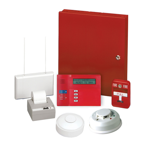
The ES-50XC is the latest intelligent addressable fire alarm control
panel (FACP) from Fire•Lite Alarms and is a direct replacement for
the MS-9050UD/LSC. The ES-50XC comes with a pre-installed
commu-nicator and supports up to 50 addressable devices in any
combina-tion of detectors or modules. With an extensive list of
powerful features, the ES-50XC programs just like Fire•Lite’s other
address-able products, yet
fits into app lications previously served
only by con-ventional panels.
The pre-installed IPOTS-COM is a dual technology (POTS and IP)
communicator. The POTS transmits system status (alarms, troubles,
AC loss, etc.) to a Central Station via the public switched telephone
network. The IP communicator’s internet monitoring capability sends
alarm signals over the Internet saving the monthly cost of two dedi-
cated business telephone lines. Although not required, the second-
ary telephone line may be retained providing backup communication
over the public switched telephone line. Optional cellular reporting is
available using the CELL-MODC or CELL-CAB-FLC.
Remote and local programming of the control panel is possible using
the FS-Tools Upload/Download utility. Programming databases can
be uploaded/downloaded via the panel’s USB port (and USB cable)
or via an ethernet connection using the IPOTS-COM communicator.
The USB port also allows for the download or upload of the entire
program, history file, walk-test data, current status and system volt-
ages by means of a USB flash drive.
The power supply and all electronics are contained on a circuit board
supported on a new quick install chassis and housed in a metal cab-
inet. Available accessories include local and remote upload/down-
load software, remote annunciators, and reverse polarity/city box
transmitter (4XTMF).
Features
• ULC Listed
• Pre-installed IPOTS-COM Ethernet IP and POTS (Plain Old Tele-
phone Service) Central Station Communicator
• Optional CELL-MODC or CELL-CAB-FLC GSM Central Station
Communicator over AlarmNet
• Auto-programming (learn mode) reduces installation time.
Reports two devices set to the same address
• Two independently programmable, built-in Style Z (Class A) or
Style Y (Class B) NAC circuits
• Selectable strobe synchronization for System Sensor, Wheelock,
and Gentex devices
• Notification Appliance Circuit End of Line resistor matching
• Four programmable function keys for ease of maintenance
• Two programmable relays and one fixed trouble relay
• Built-in Programmer
• Integral 80-character LCD display with backlighting
• Real-time clock/calendar with automatic daylight savings control
• History file with 1,000 event capacity
• Addressable sounder base
• Control module delay timer
• Automatic detector sensitivity testing
• Automatic device type-code verification
• Point trouble identification
• Waterflow selection per module point
• Alarm verification selection per detector point
• Maintenance alert warns when smoke detector dust accumulation
is excessive
• One-person audible or silent walk test with walk-test log and print-
out
• System alarm verification selection per detector point
• Up to 16 ANN-BUS annunciators- 8 per each ANN-Bus
• Remote Acknowledge, Alarm Silence, Reset and Drill via
addressable modules or remote annunciator
• Upload/Download of program and data via USB with optional FS-
Tools Programming Utility
DCL COMMUNICATION LOOP
• LiteSpeed™ polling protocol for faster DCL response time
• DCL operates up to 10,000 ft. (3,000 m) in LiteSpeed mode with
twisted, unshielded wire
• Single addressable DCL loop which meets Class B and Class A
requirements
• 50 addressable device capacity (any combination of addressable
detectors and modules)
• Compatible with Fire•Lite’s addressable devices (refer to the DCL
Wiring Manual #51309)
NOTIFICATION APPLIANCE CIRCUITS (NACS)
• Two independently programmable output circuits. Circuits can be
configured for the following outputs:
–StyleY(Class B)
–StyleZ(Class A)
• Silence Inhibit and Autosilence timer options
• Continuous, March Time, or Temporal code for main circuit board
NACs with two-stage capability
• Selectable strobe synchronization per NAC
• 2.5 A special application, 250mA regulated, total power for NACs
NOTE: Maximum or total 24VDC system power shared between all NAC
circuits and the ANN-BUS is 2.7 A
PROGRAMMING AND SOFTWARE
• Autoprogramming (learn mode) reduces installation time
• Custom English labels (per point) may be manually entered or
selected from an internal library file
• Two programmable Form-C relay outputs
• 50 software zones
Page 2 of 4 — Canadian DF-60954:C • 7/16/2018
• Continuous fire protection during online programming
• Program Check automatically catches common errors not linked
to any zone or input point
•OFFLINE PROGRAMMING: Create the entire program in your
office using FS-Tools, a Windows®-based software package, and
upload/download system programming locally. Offline program-
ming requires an ethernet connection. FS-Tools is available on
www.firelite.com.
User interface
LED INDICATORS
• Fire Alarm (red)
• AC Power (green)
• Supervisory (yellow)
• Trouble (yellow)
• Ground fault (yellow)
• Battery fault (yellow)
• Disabled (yellow)
• Maintenance (yellow)
• Communication (yellow)
• Alarm Silenced (yellow)
• F1-F4 Function Keys (yellow)
KEYPAD
• 16 key alpha-numeric pad
• Acknowledge
• Alarm Silence
• Drill (Manual Evacuate)
• Reset (lamp test)
• Four (4) programmable function keys
Product Line Information
ES-50XC: Addressable Fire Alarm Control Panel with one DCL loop.
Includes main circuit board with display, pre-installed communicator,
chassis with transformer, dress panel, backbox with door, plastic bag
containing screws, cables, key, etc., manual.
FS-Tools: Programming software for Windows®-based PC com-
puter. Available for download at www.firelite.com.
CELL-CAB-FLC/CELL-MODC: Optional GSM communicators.
TR-CE: Optional trim ring for semi-flush mounting.
BB-2F: Optional cabinet for one or two modules.
BB-6F: Optional cabinet for up to six modules mounted on CHS-6
chassis.
BB-26: Battery backbox, holds up to two 25 AH batteries and CHG-
75.
BB-55F: Battery box, housestwo 55 AH batteries
CHS-6: Chassis, mounts up to six multi-modules in a BB-6F cabinet.
CHG-75: Battery charger for lead-acid batteries with a rating of 25to
75 AH.
CHG-120F: Remotebattery charging system for lead-acid batteries
with a rating of 55 to 120 AH. Requires additional BB-55F for mount-
ing.
BAT Series: Batteries, see data sheet DF-52397.
PRN Series: ULC listed compatible event printer. Uses tractor-fed
paper.
OPTIONAL MODULES
4XTMF Reverse Polarity Transmitter Module: Provides a super-
vised output for local energy municipal box transmitter, alarm and
trouble. Includes a disable switch and disable trouble LED.
COMPATIBLE ANNUNCIATORS
ANN-100: Remote LCD annunciator mimics the information dis-
played on the FACP LCD display. Recommended wire type is un-
shielded.
ANN-I/O: LED Driver Module provides connections to auser sup-
plied graphic annunciator. (See DF-52430.)
ANN-LED: Annunciator Module provides three LEDs for each zone:
Alarm, Trouble, and Supervisory. Ships with red enclosure. (See
DF-60241.)
ANN-RLED: Provides alarm (red) indicators for up to 30 input zones
or addressable points. (See DF-60241.)
ANN-RLY: Relay Module provides 10 programmable Form-C relays.
Can be mounted inside the cabinet. (See DF-52431.)
ANN-S/PG: Serial/Parallel Printer Gateway module provides a con-
nection for a serial or parallel printer. (See DF-52429.)
ADDRESSABLE DEVICES
All feature a polling LED and rotary switches for addressing.
SD365A: Addressable low-profile photoelectric smoke detector. Lite-
Speed only.
SD365A-IV: Addressable low-profile photoelectric smoke detector.
Ivory. LiteSpeed and CLIP mode.
SD365TA: Addressable low-profile photoelectric smoke detector
with thermal sensor. LiteSpeed only.
SD365TA-IV: Addressable low-profile photoelectric smoke detector
with thermal sensor. Ivory. LiteSpeed and CLIP mode.
SD365RA: Remote test capable addressable photoelectric smoke
detector for use with DNRA duct detector housing. LiteSpeed only.
SD365RA-IV: Remote test capable addressable photoelectric
smoke detector for use with DNRA duct detector housing. Ivory. Lite-
Speed and CLIP mode.
H365A: Low-profile 135°F fixed thermal sensor. LiteSpeed only.
H365A-IV: Low-profile 135°F fixed thermal sensor. Ivory. LiteSpeed
and CLIP mode.
H365RA: Low-profile, intelligent, rate-of-rise thermal sensor. Lite-
Speed only.
H365RA-IV: Low-profile, intelligent, rate-of-rise thermal sensor.
Ivory. LiteSpeed and CLIP mode.
H365HTA:Low-profile intelligent 190°F/88°C fixed thermal sensor.
LiteSpeed only.
H365HTA-IV:Low-profile intelligent 190°F/88°C fixed thermal sen-
sor. Ivory. LiteSpeed and CLIP mode.
Legacy Devices
CP355A: Addressable low-profile ionization smoke detector.
SD355A/SD365A: Addressable low-profile photoelectric smoke
detector.
SD355TA/SD365TA: Addressable low-profile photoelectric smoke
detector with thermal sensor.
SD355RA/SD365RA: Remotetestcapable addressable photoelec-
tric smoke detector for use with DNRA duct detector housing.
H355A/H365A: Fast-response, low-profile heat detector.
H355RA/H365RA: Fast-response, low-profile heat detector with
rate-of-rise option.
H355HTA/H365HTA: Fast-response, low-profile heat detector that
activates at 190°F/88°C.
AD355A: Low-profile, intelligent, “Adapt” multi-sensor detector
(B350LP base included).
B200SA: Programmable, addressable sounder base.
B200SRA: Addressable sounder base.
BEAM355A: Intelligent beam smoke detector.
BEAM355SA: Intelligent beam smoke detector with integral sensitiv-
ity test.
D355PLA: InnovairFlex low-flow non-relay duct-detector housing;
includes SD355RA/SD365RA.
DNRA: InnovairFlex low-flow non-relay duct-detector housing.(Order
SD355RA/SD365RA separately.)
Canadian DF-60954:C • 7/16/2018 — Page 3 of 4
MMF-300A: Addressable Monitor Module for one zone of normally-
open dry-contact initiating devices. Mounts in standard 4.0" (10.16
cm.) box. Includes plastic cover plate and end-of-line resistor. Mod-
ule may be configured for either a Style B (Class B) or Style D (Class
A) IDC.
MDF-300A: Dual Monitor Module. Same as MMF-300A except it
provides two Style B (Class B) only IDCs.
MMF-301A: Miniature version of MMF-300A. Excludes LED and
Style D option. Connects with wire pigtails. May mount in device
backbox.
MMF-302A: Similar to MMF-300A. Addressable Monitor Module for
one zone of conventional two-wire detectors. Requires resettable 24
VDC power. Refer to the Device Compatibility Document for listed
compatible devices and quantity limitation.
CMF-300A: Addressable Control Module for one Style Y/Z (Class B/
A) zone of supervised polarized Notification Appliances. Mounts
directly to a 4.0" (10.16 cm.) electrical box. Notification Appliance
Circuit option requires external 24 VDC to power notification appli-
ances.
CRF-300A: Addressable relay module containing two isolated sets
of Form-C contacts, which operate as a DPDT switch. Mounts
directly to a 4.0" (10.16 cm.) box, surface mount using the SMB500.
BG-12LX: Addressable manual pull station with interface module
mounted inside.
I300A: This module isolates the DCL loop from short circuit condi-
tions (required for Style 6 or 7 operation).
ISO-6A: Six-fault isolator module. Mount one or two modules in a
BB-2F cabinet (optional). Mount up to six modules on a CHS-6 chas-
sis in a BB-6F cabinet.
SMB500: Used to mount all modules except the MMF-301A and
M301A.
MMF-300-10A: Ten-input monitor module. Mount one or two mod-
ules in a BB-2F cabinet (optional). Mount up to six modules on a
CHS-6 chassis in a BB-6F cabinet.
MMF-302-6A: Six-zone interface module. Mount one or two mod-
ules in a BB-2F cabinet (optional). Mount up to six modules on a
CHS-6 chassis in a BB-6F cabinet.
CMF-300-6A: Six-circuit supervised control module. Mount one or
two modules in a BB-2F cabinet (optional). Mount up to six modules
on a CHS-6 chassis in a BB-6F cabinet.
CRF-300-6A: Six-relay control module (Form-C relays). Mount one
or two modules in a BB-2F cabinet (optional). Mount up to six mod-
ules on a CHS-6 chassis in a BB-6F cabinet.
NOTE: For more information on Compatible Addressable Devices for
use with the EX-50XC, see the following data sheets (document num-
bers): AD355 (DF-52386), BG-12LX (DF-52013), CMF-300-6
(DF-52365), CRF-300-6 (DF-52374), CMF/CRF Series (DF-52130),
CP355 (DF-52383), H355 Series (DF-52385), I300 (DF-52389),
ISO-6 (DF-60485), MMF-300 Series/MDF-300 (DF-52121),
MMF-300-10 (DF-52347), MMF-302-6 (DF-52356), SD355/SD355T
(DF-52384), and the DCL Wiring Manual (51309).
NOTE: Legacy 300 Series detection devices such as the CP300A/
CP350A, SD300A(TA)/SD350A(TA) and older modules such as the
M300A, M301A, M302A, C304A, and BG-10LX are not compatible with
LiteSpeed polling. If the DCL contains one of these devices, polling must
be set for standard CLIP protocol. Please consult factory for further infor-
mation on previous 300 Series devices.
ADDRESSABLE DEVICE ACCESSORIES
End-of-Line Resistor Assembly (R-47K and R-3.9K): The
47k ohm assembly supervises the MMF-300A, MDF-300A,
MMF-301A, and CMF-300A module circuits. The 3.9k ohm
assembly supervises the MMF-302A module circuit. These
resistors are included with each module.
Power Supervision Relay: Supervises the power to 4-wire smoke
detectors and notification appliances.
Wiring Requirements
While shielded wire is not required, it is recommended that all DCL
wiring be twisted-pair to minimize the effects of electrical interfer-
ence. Refer to the panel manual for wiring details.
Page 4 of 4 — Canadian DF-60954:C • 7/16/2018
This document is not intended to be used for
installation purposes. We try to keep our product
information up-to-date and accurate. We cannot
cover all specific applications or anticipate all
requirements. All specifications are subject to
change without notice.
For more information, contact Fire•Lite Alarms.
(888) 289-1114
10 Whitmore Road
Woodbridge, Ontario LZL 7Z4
www.firelite.com
LiteSpeed™ is a trademark and Fire-Lite® Alarms and System Sensor® are
registered trademarks of Honeywell International Inc. Microsoft® and Windows® are
registered trademarks of the Microsoft Corporation.
©2018 by Honeywell International Inc. All rights reserved. Unauthorized use of this
document is strictly prohibited.
SYSTEM SPECIFICATIONS
System Capacity
• Intelligent Digital Communication Loops ....................................1
• Addressable device capacity ....................................................50
• Programmable software zones .................................................50
• Annunciators.............................................................................16
Electrical Specifications
AC Power: Operates in either 120 or 240 VAC, 50/60 Hz, 1.75 A,
auto-sensing-no switch required. Wire size: minimum 14 AWG (2.00
mm2) with 600 V insulation. Nonpower-limited, super-vised.
Battery: Two 12 V 18 AH lead-acid batteries. Battery Charger
Capacity: 7-18 AH (EX-50XC cabinet holds maximum of two 18 AH
batteries.)
Digital Communication Loop: Supervised and power-limited.
Notification Appliance Circuits: Terminal Block provides connec-
tions for two NACs, Style Y (Class B) or Style Z (Class A). Special
Application power. Power-limited, supervised circuitry. Maximum sig-
naling current per circuit: 2.5 amps special application, 250mA regu-
lated. End-of-Line Resistor: 4.7k ohm, ½ watt (P/N 71252 UL listed)
for Style Y (Class B) NAC; system capable of 1.9 kΩ- 22 kΩELR
range. Refer to the Fire•Lite Device Compatibility Document for
listed compatible devices.
Two Programmable Relays and One Fixed Trouble Relay: Con-
tact rating: 2.0 A@ 30 VDC (resistive), 0.5 A@ 30 VAC (resistive).
Form-C relays, non-power-limited, non-supervised.
Cabinet Specifications
Door: 19.26" (48.92 cm.) high x 16.82" (42.73 cm.) wide x 0.72"
(1.82 cm.) deep. Backbox: 19.00" (48.26 cm.) high x 16.65" (42.29
cm.) wide x 5.25" (13.34 cm.) deep. Trim Ring (TR-CE): 22.00"
(55.88 cm.) high x 19.65" (49.91 cm.) wide.
Shipping Specifications
Weight: 26.9 lbs. (12.20 kg.) Dimensions: 20.00” (50.80 cm.) high
x 22.5” (57.15 cm.) wide x 8.5” (21.59 cm.) deep.
Temperature and Humidity Ranges
This system meets requirements for operation at 0 – 49°C and at a
relative humidity 93% ± 2% RH (non-condensing) at 32°C ± 2°C.
However, the useful life of the system's standby batteries and the
electronic components may be adversely affected by extreme tem-
perature ranges and humidity. Therefore, it is recommended that this
system and its peripherals be installed in an environment with a nor-
mal room temperature of 15 – 27°C.
Agency Listings and Approvals
The listings and approvals below apply to the basic ES-50XC control
panel. In some cases, certain modules may not be listed by certain
approval agencies, or listing may be in process. Consult factory for
latest listing status.
•ULC: S624

Other Honeywell Security System manuals

Honeywell VISTA-21iP User manual

Honeywell

Honeywell VISTA-21iP User manual

Honeywell Optiflex Interactive User manual

Honeywell

Honeywell Optiflex Interactive User manual

Honeywell Galaxy Dimension User manual

Honeywell

Honeywell Galaxy Dimension User manual

Honeywell LYNX Touch L7000 Series User manual

Honeywell

Honeywell LYNX Touch L7000 Series User manual

Honeywell Lynx Plus Series Operating instructions

Honeywell

Honeywell Lynx Plus Series Operating instructions

Honeywell VISTA 21iPLTE User manual

Honeywell

Honeywell VISTA 21iPLTE User manual

Honeywell 3516 User manual

Honeywell

Honeywell 3516 User manual

Honeywell TCPA2B User manual

Honeywell

Honeywell TCPA2B User manual

Honeywell sixsiren User manual

Honeywell

Honeywell sixsiren User manual

Honeywell Domonial User manual

Honeywell

Honeywell Domonial User manual

Honeywell WAVE2EX - Ademco Two Tone Siren Assembly instructions

Honeywell

Honeywell WAVE2EX - Ademco Two Tone Siren Assembly instructions

Honeywell LYNX Touch Security System User manual

Honeywell

Honeywell LYNX Touch Security System User manual

Honeywell Galaxy 2 Series User manual

Honeywell

Honeywell Galaxy 2 Series User manual

Honeywell nfs2-3030 User manual

Honeywell

Honeywell nfs2-3030 User manual

Honeywell LYNX Touch Security System User manual

Honeywell

Honeywell LYNX Touch Security System User manual

Honeywell ADEMCO LYNXR Series Assembly instructions

Honeywell

Honeywell ADEMCO LYNXR Series Assembly instructions

Honeywell Lyric User manual

Honeywell

Honeywell Lyric User manual

Honeywell X-618 User manual

Honeywell

Honeywell X-618 User manual

Honeywell Ademco VISTA-32FB Operating instructions

Honeywell

Honeywell Ademco VISTA-32FB Operating instructions

Honeywell INTELLIGUARD 9000 User manual

Honeywell

Honeywell INTELLIGUARD 9000 User manual

Honeywell 2202 User manual

Honeywell

Honeywell 2202 User manual

Honeywell Fire-Lite Alarms ES-200X Owner's manual

Honeywell

Honeywell Fire-Lite Alarms ES-200X Owner's manual

Honeywell PROSiXSIRENO Assembly instructions

Honeywell

Honeywell PROSiXSIRENO Assembly instructions

Honeywell Home SI800MS User manual

Honeywell

Honeywell Home SI800MS User manual

Popular Security System manuals by other brands

ABB SAS-W1.1E System manual

ABB

ABB SAS-W1.1E System manual

Elk Products ELK-6030P Installation and setup guide

Elk Products

Elk Products ELK-6030P Installation and setup guide

X10 VT38A owner's manual

X10

X10 VT38A owner's manual

Ampac FireFinder PLUS Installation, comissioning & operation

Ampac

Ampac FireFinder PLUS Installation, comissioning & operation

Eminent EM8660 manual

Eminent

Eminent EM8660 manual

Ultra Start 500 Series owner's guide

Ultra Start

Ultra Start 500 Series owner's guide

Defender CA6000 owner's manual

Defender

Defender CA6000 owner's manual

Meridian Euro user manual

Meridian

Meridian Euro user manual

Robotics Technologies Bus-Scan ALERT Installation & operation manual

Robotics Technologies

Robotics Technologies Bus-Scan ALERT Installation & operation manual

Vipro AVM100 user manual

Vipro

Vipro AVM100 user manual

Apollo 51000-357 installation guide

Apollo

Apollo 51000-357 installation guide

Memco C100 LVAS installation guide

Memco

Memco C100 LVAS installation guide

Ansul 100/30 Operation and maintenance manual

Ansul

Ansul 100/30 Operation and maintenance manual

chinavasion CVSL-I194 user manual

chinavasion

chinavasion CVSL-I194 user manual

Siemens MI291A maintenance

Siemens

Siemens MI291A maintenance

Teknim VAS 740 F Mounting and User Manual

Teknim

Teknim VAS 740 F Mounting and User Manual

Vanderbilt GMAS6 installation manual

Vanderbilt

Vanderbilt GMAS6 installation manual

Sentrol ZXLCD user manual

Sentrol

Sentrol ZXLCD user manual

manuals.online logo
manuals.online logoBrands
  • About & Mission
  • Contact us
  • Privacy Policy
  • Terms and Conditions

Copyright 2025 Manuals.Online. All Rights Reserved.