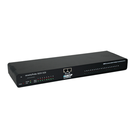
AKCP SecurityProbe 5ES-X20 User manual

www.AKCP.com
SecurityProbe
5ES-X20/X60
User Manual
Help Version updated till firmware 403H
Copyright © 2011, AKCP Co., Ltd..

securityProbe 5ES securityProbe 5ES-X20 Manual
Updated until firmware 403H - 2 -
1) Introduction
1. What is securityProbe 5E Standard?
2. How to use this manual
3. Package Contents
4. Front and Rear Panels
2) Installation
1. Setting the IP address
2. Testing the IP address
3. Firmware upgrade
4. Multi User Groups and Management
5. Services and Security
6. Setting up a sensor
i) Notification thresholds
ii) Advanced sensor settings
7. Expansion Ports
3) Notifications
1. Adding a notification
2. SNMP trap
3. E Mail
4. SMS notification
4) Mapping
1. Adding a map
2. Monitoring via map interface
5) Filters
1. Sensor filters
2. Syslog filters
6) Making my unit visible to the internet
7) FAQ

securityProbe 5ES securityProbe 5ES-X20 Manual
Updated until firmware 403H - 3 -
1) Introduction
What is securityProbe 5E “Standard”?
The securityProbe-5ES Standard integrates over 10 years of environmental monitoring
experience with the latest technology to push the boundaries of disaster protection. Now
you can sense and see problems before they lead to business disruptions. It is a high
speed, accurate, intelligent monitoring device, featuring a completely embedded host and
Linux Operating System. The design is based on our successful securityProbe 5E, but
without the camera inputs. This gives you everything you need and nothing you don't!
AKCP has prided itself on bringing a low cost, easy to use monitoring solution to market with
the securityProbe-5ES.
What’s the difference between the securityProbe 5ES and
the securityProbe 5ES-X20?
The securityProbe 5E-X20 has the 8 RJ-45 intelligent sensor ports AND has 20 extra dry
contact inputs, where the securityProbe 5E only has the 8 RJ-45 sensor ports. More on
these extra dry contacts in the sections below.
How to use this manual
This manual is meant to provide the user with a step by step guide on how to configure
and set up their unit. It utilizes screen shots in an effort to make things simpler for the
user to follow. It is split up into sections that form “mini tutorials”. These cover the basic
set up and common configurations of the unit, and give an introduction to its most useful
features.
At the end of the manual there is a FAQ section that provides some further in-depth
information regarding specific set ups and answers some commonly asked questions. If
you need any further information or help with using your unit then please contact us on
support@akcp.com and one of our technical support staff will be only to pleased to help
you with any information you require.
Package Contents
Your Securityprobe-5ES package contains the following items:-
1x Product CD
1x 5ft Crossover cable
1x THS00 with 5 ft straight cable
1x 7.0 –9 V, 2.5 A power supply
2x Brackets for rack mounting
1x Blue quick-start guide.

securityProbe 5ES securityProbe 5ES-X20 Manual
Updated until firmware 403H - 4 -
Front and rear panels
securityProbe 5ES
Fig 1. Front panel
The front panel has several LEDs which display the units status and notify you as to its
activity.
1. Power LED
When the unit is powered up the power LED will be lit continuously. If the power LED
is flashing then it indicates a problem with the CPU. If you notice this then please
2. Ethernet LED
The Activity and Link LEDs indicate network connectivity and activity. The Link LED
will light up when there is a network connection present. The activity LED will flash
when there is network traffic being sent or received by the unit.
3. Status / Online LEDs
These are numbered 1 –8. They are used to indicate the connectivity status of the
sensors connected to each port. These LEDs also can be used to indicate system
status when undertaking various operations.
1. The LEDs will indicate the progress of an upgrade. The red LEDs will move
from left to right to indicate activity, and the green LEDs will indicate overall
progress of the upgrade. When all the red lights are off and all green are on
the upgrade / recovery process is complete.
2. These lights will indicate if the unit is operating in safe mode. This is when
the unit loads the Operating System (OS) with a minimal set of drivers. If
your device enters safe mode after rebooting then please contact us on
support@akcp.com
3. The unit may enter recovery mode if a firmware upgrade has been
incomplete. This will be indicated by the unit displaying a continuously lit row
of red LEDs. If this happens please contact us on support@akcp.com
4. Mic
The mic is a small hole for access to the internal microphone. This can be used as a
sound sensor (or an external mic can be used)

securityProbe 5ES securityProbe 5ES-X20 Manual
Updated until firmware 403H - 5 -
5. Expansion Ports
There are four expansion ports numbered from E1 –E4. These are expansion Ports
for connecting either the 8port expansion or 16 dry contact expansion modules.
6. Removable SD slot
This slot so where you can place your SD card which can store data such as pictures
taken from the CCTV camera, sounds recorded from the internal microphone, and
also the current firmware of the unit.
Fig 2. Rear panel.
The rear panel of the unit is home to various ports and connections. The functions of
these are as follows :-
1. Reset button
The black tact switch button is used to perform the following functions
1. A single press will announce the IP address of the unit. This is audible
through the internal speaker. It also broadcasts the IP address to the IPset
program.
2. Turns off password checking when accessing the web based interface (hold
down for 7 seconds)
3. To reboot the unit into the firmware upgrade mode (hold down for 12
seconds)
2. Sensor ports
There are 8 RJ45 ports numbered from 1 –8. These are for connecting AKCP
intelligent sensors to the unit.
3. USB port
The unit is equipped with one USB 1.1 port. This can be used, for example, to
connect a USB GPRS/GSM compatible modem, a USB WiFi dongle or USB
Bluetooth dongle.
4. Mic Out
This is used to connect an external microphone for voice modem applications.

securityProbe 5ES securityProbe 5ES-X20 Manual
Updated until firmware 403H - 6 -
5. Audio in / out
The in is used to connect an external microphone, the output for external speakers.
6. RS485 Port
Used for Modbus connectivity. We support Modbus master or slave.
7. Power Connector
This is a 7.5V DC plug. We recommend you using a 7.0 –9 V, 2.5 A power supply.
8. Ethernet Port
This RJ45 port is used to connect your unit to the network.
9. External ground
The EXT. GND can be used to external ground the unit.
securityProbe 5ES-X20
securityProbe 5ES-X20 20 Extra Dry Contact Inputs
The 20 extra dry contact inputs on for example, the securityProbe 5ES-X20, (or
securityProbe 5ES-X60) can be configured as inputs only up to 5 Volts in normal
operation. In opto-isolation mode they can input up to 30 Volts DC. This will protect these
inputs and the unit from high voltages and spikes.
Opto-isolators provide complete electrical separation between the securityProbe 5ES-
X20 and the dry contact. The base units are therefore protected against possible large
voltage spikes caused by lightning for example.
The figure below shows the JUMPERS (on the dry contact board) set up to provide opto-
isolators support. Opto-isolators provide complete electrical separation between the
securityProbe 5ES-X20 and the dry contact.
Please refer to the rear panel of the securityProbe 5ES above for the other connections
on the rear panel as they are exactly the same in functionality.

securityProbe 5ES securityProbe 5ES-X20 Manual
Updated until firmware 403H - 7 -
The OID for the extra dry contact inputs is:- .1.3.6.1.4.1.3854.1.2.2.1.18.1.3.<port>
Extra dry contact input practical applications:
The extra dry contact inputs can be used to monitor many types of equipment, for example, you
can run the connection from warning lights on alarm panels to the dry contact inputs, so that
when the warning light on the alarm panel is activated, the dry contact is triggered in the units
web interface, thus allowing you to send notifications via emails or SNMP traps.
securityProbe 5ES-X20 extra dry contact web interface setup
First login to the securityProbe 5ES-X20 web interface, then navigate to the Sensors Page, then
click on the Dry Contact Ports link in the left hand column. You can now click on the dry contact
port to setup that port as shown in the screen shot above.

securityProbe 5ES securityProbe 5ES-X20 Manual
Updated until firmware 403H - 8 -
In the Normal tab settings we can see that the sensor is currently Offline, so to enable the dry
contact port we would click on the Offline button.
Now we can see the dry contact input is now Critical and we can set how we require the Normal
State to be in as shown above. Either in the Closed GND or Open +5VDC. We can also rename
our normal and critical state of the input.

securityProbe 5ES securityProbe 5ES-X20 Manual
Updated until firmware 403H - 9 -
Now we can see that the dry contact input now is in the normal state as shown in the screen shot
above.
If we click on the Advanced Tab, we can set the graphing to on, the sensor URL, set the Filter
Status and enable the Calendar. (More on the Sensor URL and Filter Status in sections #)

securityProbe 5ES securityProbe 5ES-X20 Manual
Updated until firmware 403H - 10 -
2) Installation
1. Setting up the IP address
Every unit is shipped with the default IP address of 192.168.0.100 First we will go through
the process of changing this IP address to fit your own network configuration.
Ensure the following items are available to you before starting:-
1. RJ45 CAT5 crossover cable with RJ45 male connection
2. A PC with Ethernet card or LAN socket.
3. Power socket for the unit to connect to
a) Connect the unit via the Ethernet port of the unit to your computers LAN or Ethernet
port with a CAT5 crossover cable.
b) Open a web browser and type the default IP address, hit enter.
In some cases your computer might not be able to connect to this default IP address. In
this situation you need to set up your computers routing table to allow access to this. See
the appendix on how to setup this.
c) You will now be presented with the following screen. The default password for Admin
is “public”. To make your unit secure and change the password.

securityProbe 5ES securityProbe 5ES-X20 Manual
Updated until firmware 403H - 11 -
d) Next the home page will be displayed. It will look similar to this.
e) Click on “Ethernet network” from the list on the left frame of the page.

securityProbe 5ES securityProbe 5ES-X20 Manual
Updated until firmware 403H - 12 -
Note. The unit ships with DHCP disabled. If you wish to use a DHCP server to obtain the
IP address then see the “Using DHCP” section of the FAQ>

securityProbe 5ES securityProbe 5ES-X20 Manual
Updated until firmware 403H - 13 -
2. Testing the new IP address with the “ping” command
Once you have assigned the new IP address use the “ping” command to test the unit.
This can also be used as a diagnostic tool in order to check whether your unit is
connected to the network.
After hitting “enter” you will get an MS DOS prompt window that will show the ping results
(as below). If unsuccessful you will get a message saying “request timed out”. This
indicates either an incorrect IP address or a unit that is not connected to the network.

securityProbe 5ES securityProbe 5ES-X20 Manual
Updated until firmware 403H - 14 -
3. Firmware upgrade
Ensure you are running the latest firmware. You will also need to download the latest firmware
from our website ( http://www.akcp.com/company/firmwareupdate.htm ). Log into our webpage
using your MAC address, this is found on a sticker on the base of the unit. After the download
navigate back to the web based interface (units IP address. This manual will refer to the
DEFAULT IP address, 192.168.0.1 you need to substitute this for your own IP address if you
have changed it)
a)
This tutorial provides you the information needed to upgrade the firmware.
To get to the starting point of this tutorial:
Log in as administrator
Click on the settings tab

securityProbe 5ES securityProbe 5ES-X20 Manual
Updated until firmware 403H - 15 -
b)
c) You will then be presented with this pop up :-
Click OK. The unit will then reboot in safe mode. After reboot you will be redirected to the safe
mode web interface. This can take some time, so please be patient. The page will display the
following message while rebooting
d) Once the unit has rebooted you will be viewing the following page. Follow these
instructions.

securityProbe 5ES securityProbe 5ES-X20 Manual
Updated until firmware 403H - 17 -
Multi-users and groups setup
Login to the securityProbe or securityProbe 5E with the Administrator password, the default
will be “public” if you have not changed this yet.
Click on the Settings page, then System Administrator then User & Group Management as
shown in the screen shot below:
Note:The following screen shots may appear small and hard to read. Please use the
zoom feature in your PDF reader program to increase the size of the page to better view
these screen shots.
1) Group Setup
This will take you to the Groups page shown below:-
Now click on the “Add” button to add your groups as shown in the screen shot above.

securityProbe 5ES securityProbe 5ES-X20 Manual
Updated until firmware 403H - 18 -
Enter your group name for example we have added a group named “System Guest” and entered
our description.
Now check the objects within the web interface that this group will be able to Modify and View.
Then click the “Finish” button to save your group.
Now you can see the new group “System Guest” has been added to our group list as shown in
the screen shot above.

securityProbe 5ES securityProbe 5ES-X20 Manual
Updated until firmware 403H - 19 -
If you wish to modify your group settings, highlight the group you wish to modify by clicking on it,
then click on the “Properties” button as shown in the screen shot above.

securityProbe 5ES securityProbe 5ES-X20 Manual
Updated until firmware 403H - 20 -
2) User Setup
Click on the Users tab then click the “Add” button to add the new Users to your groups as shown
above.
Now enter your User details as shown above. In our example we have entered Bob Smith as our
Guest into our “System Guest” group. We have also added the option so that this user cannot
change his login password. After addition your users for each group click the “Finish” button to
save each user.
This manual suits for next models
1
Table of contents
Other AKCP Security System manuals
Popular Security System manuals by other brands

Visonic
Visonic PMASTER20G2 Installer's guide

RS
RS 408-735 manual

ACR Electronics
ACR Electronics THUNDERBIRD S.S.A.S. Product support manual

ADT
ADT On-The-Go Emergency Response System Quick installation guide

myCam
myCam VPG-OAP1080KIT Installation and operating instructions

WiLife
WiLife DVS-800i user guide