Powerware 3110 User manual

POWERWARE®3110
250 VA600 VA
User's Guide
www.powerware.com
B

Powerware is a registered trademark of Powerware Corporation.
Copyright 2001 Powerware Corporation, Raleigh, NC, USA. All rights reserved. No part of this document may be
reproduced in any way without the express written approval of Powerware Corporation.

i
Powerware®3110 User's Guide 05147486 B (English) Uncontrolled Copy
TABLE OF CONTENTS
1 Installation 1. . . . . . . . . . . . . . . . . . . . . . . . . . . . . . . . . . . . . . . . . . . . . . . . . .
Inspecting the Equipment 1. . . . . . . . . . . . . . . . . . . . . . . . . . . . . . . . . . . . . . . . . . . . . . . . . . . . . .
Safety Precautions 1. . . . . . . . . . . . . . . . . . . . . . . . . . . . . . . . . . . . . . . . . . . . . . . . . . . . . . . . . .
Quick Startup 2. . . . . . . . . . . . . . . . . . . . . . . . . . . . . . . . . . . . . . . . . . . . . . . . . . . . . . . . . . . . . .
UPS Top and Side Panels 3. . . . . . . . . . . . . . . . . . . . . . . . . . . . . . . . . . . . . . . . . . . . . . . . . . . . . .
2 Features 5. . . . . . . . . . . . . . . . . . . . . . . . . . . . . . . . . . . . . . . . . . . . . . . . . . . . .
Communication Port 5. . . . . . . . . . . . . . . . . . . . . . . . . . . . . . . . . . . . . . . . . . . . . . . . . . . . . . . . .
Pinouts 5. . . . . . . . . . . . . . . . . . . . . . . . . . . . . . . . . . . . . . . . . . . . . . . . . . . . . . . . . . . . . . . .
Battery Start Feature 6. . . . . . . . . . . . . . . . . . . . . . . . . . . . . . . . . . . . . . . . . . . . . . . . . . . . . . . . .
Network Transient Protector 6. . . . . . . . . . . . . . . . . . . . . . . . . . . . . . . . . . . . . . . . . . . . . . . . . . . .
3 UPS Maintenance 7. . . . . . . . . . . . . . . . . . . . . . . . . . . . . . . . . . . . . . . . . . . . .
UPS and Battery Care 7. . . . . . . . . . . . . . . . . . . . . . . . . . . . . . . . . . . . . . . . . . . . . . . . . . . . . . . .
Storing the UPS 7. . . . . . . . . . . . . . . . . . . . . . . . . . . . . . . . . . . . . . . . . . . . . . . . . . . . . . . . . .
Replacing Batteries 7. . . . . . . . . . . . . . . . . . . . . . . . . . . . . . . . . . . . . . . . . . . . . . . . . . . . . . . . . .
Recycling the Used Battery 9. . . . . . . . . . . . . . . . . . . . . . . . . . . . . . . . . . . . . . . . . . . . . . . . . . . . .
4 Specifications 11. . . . . . . . . . . . . . . . . . . . . . . . . . . . . . . . . . . . . . . . . . . . . . . .
5 Troubleshooting 13. . . . . . . . . . . . . . . . . . . . . . . . . . . . . . . . . . . . . . . . . . . . . .
Service and Support 14. . . . . . . . . . . . . . . . . . . . . . . . . . . . . . . . . . . . . . . . . . . . . . . . . . . . . . . . .

Table of Contents
ii Powerware®3110 User's Guide 05147486 B (English) Uncontrolled Copy

1
Powerware®3110 User's Guide 05147486 B (English) Uncontrolled Copy
C H A P T E R 1
INSTALLATION
This section explains:
Equipment inspection
Safety precautions
UPS installation
UPS top and side panels
Inspecting the Equipment
If any equipment has been damaged during shipment, keep the shipping
cartons and packing materials for the carrier or place of purchase and
file a claim for shipping damage. If you discover damage after
acceptance, file a claim for concealed damage.
To file a claim for shipping damage or concealed damage: 1) File with
the carrier within 15 days of receipt of the equipment; 2) Send a copy of
the damage claim within 15 days to your service representative.
Safety Precautions
Read the following precautions before you install the UPS.
IMPORTANT SAFETY INSTRUCTIONS
SAVE THESE INSTRUCTIONS. This manual contains important instructions that you
should follow during installation and maintenance of the UPS and batteries. Please
read all instructions before operating the equipment and save this manual for future
reference.
WARNING
This UPS contains its own energy source (batteries). The output receptacles may
carry live voltage even when the UPS is not connected to an AC supply.
Do not remove or unplug the input cord when the UPS is turned on. This removes
the safety ground from the UPS and the equipment connected to the UPS.

Installation
2Powerware®3110 User's Guide 05147486 B (English) Uncontrolled Copy
To reduce the risk of fire or electric shock, install this UPS in a temperature and
humidity controlled, indoor environment, free of conductive contaminants. Ambient
temperature must not exceed 40°C (104°F). Do not operate near water or
excessive humidity (95% max).
With the exception of the user-replaceable battery, all servicing of this equipment
must be performed by qualified service personnel.
Before maintenance or repair, all connections must be removed. Before
maintenance, repair, or shipment, the unit must be completely switched off and
unplugged or disconnected.
CAUTION
Important Notice The UPS ground (earth) conductor carries leakage current from
the loads in addition to any leakage current generated by the UPS. This UPS
generates no more than 0.5 mA of current (120V Model), or 1 mA of current
(230V Model).
To limit the total leakage current to 3.5 mA, the load leakage must be limited to
3 mA on the 120V Model and 2.5 mA on the 230V Model.
If you do not know the load leakage current, replace the UPS power cord
(230V Model only) with a power cord that uses a locking plug with a minimum
rating of 10A (such as IEC 309).
If you do not have a matching receptacle, consult an electrician to install the
proper receptacle.
The three-wire receptacle that you plug the UPS into must have a good
(low-impedance) ground (protective earth) connection to provide a safe path for
leakage current.
Quick Startup
The Powerware 3110 provides protection against many power problems,
including power outages. It also provides spike suppression and line
noise filtering to protect your equipment.
1. On 230V Models, plug the UPS power cord into the input
connector on the UPS side panel.
2. Plug the equipment to be protected into the UPS output
receptacles.
DO NOT protect laser printers with the UPS because of the
exceptionally high power requirements of the heating elements.

Installation
3
Powerware®3110 User's Guide 05147486 B (English) Uncontrolled Copy
3. Start the UPS by pressing the switch as shown in Figure 3
or Figure 4 on page 4. The Power indicator illuminates
indicating that power is available from the UPS output
receptacles.
The units beeps and the front panel LEDs illuminate several
times. The green indicator remains on, indicating normal
operation.
If the unit continues to beep, or if the green indicator is off
even though input power is available from the wall outlet, see
Troubleshooting" on page 13.
NOTE Let the unit charge the battery for at least 3 hours. You may use the unit while
the battery charges, but the battery backup runtime will be reduced until the battery is
fully charged. This will take up to 8 hours after a full discharge while the UPS is fully
loaded.
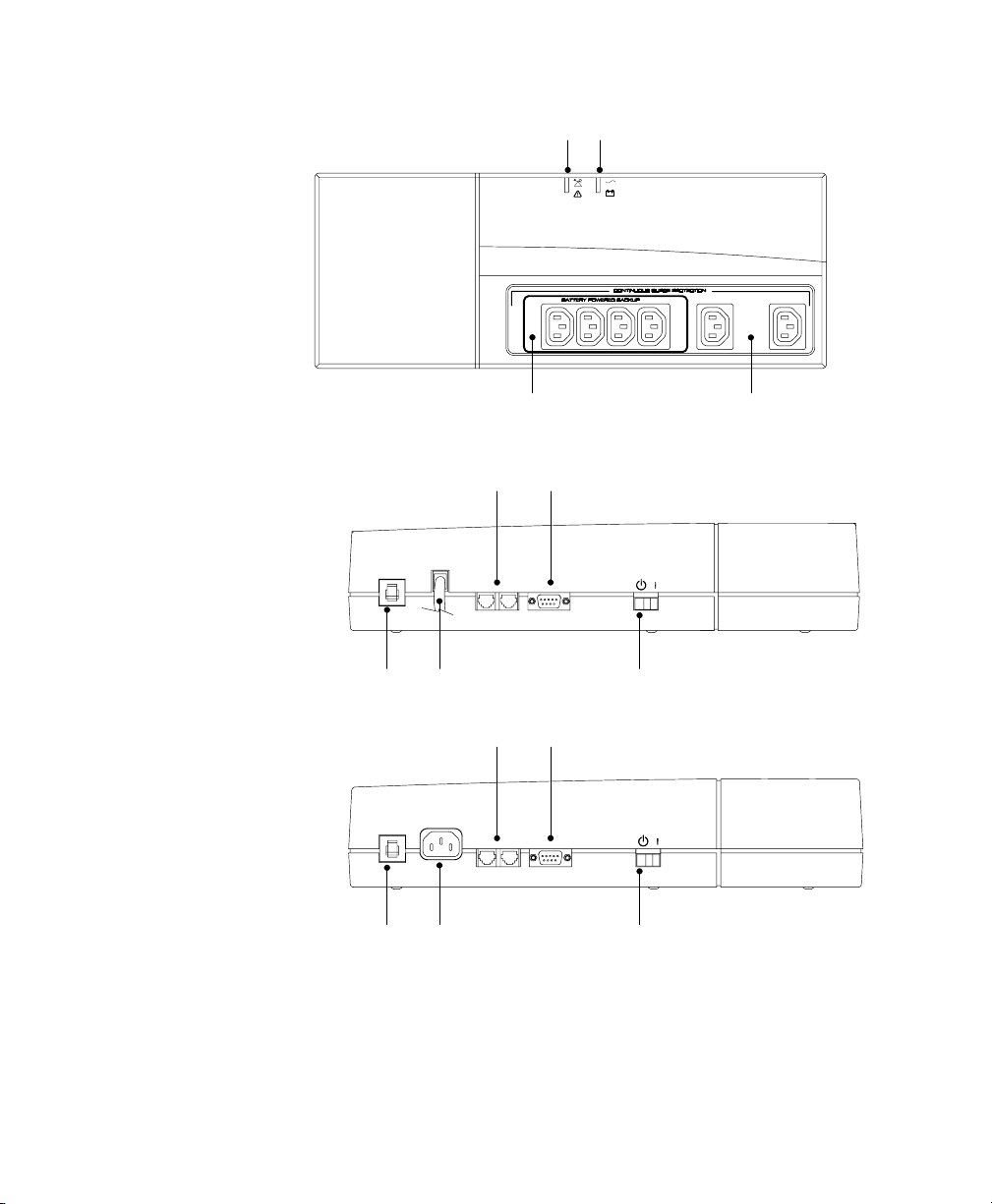
UPS Top and Side Panels
Figure 1 and Figure 3 identify features of the 120V Model (USA) units,
with attached input line cord. Figure 2 and Figure 4 identify features of
the 230V Model (European) units, which have a connector for the input
line cord as well as different output receptacles.
Fault Indicator
Output Receptacles
(Battery and Surge Protection)
Output Receptacles
(Surge Protection Only)
Power Indicator
Figure 1. 120V Model Top Panel
Installation
4Powerware®3110 User's Guide 05147486 B (English) Uncontrolled Copy
Fault Indicator
Output Receptacles
(Battery and Surge Protection)
Output Receptacles
(Surge Protection Only)
Power Indicator
Figure 2. 230V Model Top Panel
Circuit Breaker Power Cord
Network Transient Protector Communication Port
On/Standby Switch
Figure 3. 120V Model Side Panel (600 VA Shown)
Circuit Breaker Input Connector
Network Transient Protector Communication Port
On/Standby Switch
Figure 4. 230V Model Side Panel (600 VA Shown)

5
Powerware®3110 User's Guide 05147486 B (English) Uncontrolled Copy
C H A P T E R 2
FEATURES
This section covers:
Using the communication port
Starting the UPS on battery
Communication Port
Powerware Corporation offers an accessory interface kit that allows you
to connect many types of computer systems to the UPS communication
port. For specific information on Powerware Corporation interface kits,
call your service representative.
Pinouts
Contacts consist of open collector circuits capable of switching up to
+30 Vdc, 6 mA resistive load.
Table 1. Communication Port Pin Assignment
Pin Signal Type Function
1RS-232 Level Shutdown +12 Vdc signal held for 5 seconds on this pin shuts the UPS down
120 seconds later. The UPS restarts after 15 seconds when utility
power returns.
2Not Used Not Used
3Normally Open On-Battery Contact A normally open contact that closes 15 seconds (pulls to
Common) after the UPS switches to battery power.
4 Common The signal ground for all signal pins.
5Normally Open Low-Battery-Alarm Contact A normally open contact that closes (pulls to Common) during a
Low Battery Alarm.
6Normally Closed Low-Battery-Alarm Contact A normally closed contact that opens (releases from Common)
during a Low Battery Alarm. This tells some shutdown software
when to start a computer shutdown.
7Not Used Not Used
8Normally Closed On-Battery Contact A normally closed contact that opens 15 seconds (releases from
Common) after the UPS switches to battery power.
9Not Used Not Used

Features
6Powerware®3110 User's Guide 05147486 B (English) Uncontrolled Copy
Battery Start Feature
The Battery Start feature allows you to turn on the UPS when utility
power is not available. The battery-start range is up to about 40% of
nominal input; otherwise, the UPS displays an input voltage fault and
the alarm beeps.
Network Transient Protector
The Network Transient Protector is located on the side panel and has
jacks labeled IN and OUT. This feature accommodates a RJ11
telephone connector that provides protection for modems, fax machines,
or other telecommunications equipment. As with most modem
equipment, it is not advisable to use this jack in digital PBX (Private
Branch Exchange) environments.
Low voltage models can also accommodate a single RJ45 (10BaseT)
network connector.
Connect the input connector of the equipment you are protecting to the
jack labeled IN. Connect the output connector to the jack labeled OUT.
Other manuals for 3110
3
Other Powerware Power Supply manuals

Powerware
Powerware 3110 User manual

Powerware
Powerware 208/120V User manual

Powerware
Powerware 3105 User manual

Powerware
Powerware 30-160kVA User manual

Powerware
Powerware 9315 Installation and operating instructions

Powerware
Powerware 9150 User manual

Powerware
Powerware 5075 kVA User manual

Powerware
Powerware 3115 User manual

Powerware
Powerware 4500 User manual

Powerware
Powerware 5115 User manual


