PowMr POW-RELAB 3KE User manual

User Manual
POW-RELAB SERIES

User Manual
POW-RELAB SERIES
1
Important Safety Instructions
Please keep the user manual properly for future reference!
Warning: It is essential to read, understand, and adhere to all safety instructions provided in
this document. Failure to comply with safety regulations may result in property damage or
personal injury.
➢Basic Guidelines
1. Before using the equipment, carefully review all relevant sections of the device, battery, and
instruction manual for all guidance and warning signs.
2. Caution: To reduce the risk of injury, only charge deep-cycle lead-acid rechargeable batteries.
Other types of batteries may rupture, causing personal harm.
3. This product does not contain user-serviceable parts. Do not disassemble the equipment.
When maintenance or cleaning is required, take it to a qualified service center. Improper
reassembly may pose risks of short-circuiting and fire. If any panel displays a malfunction, do
not remove the front panel or operate the product. All operating procedures must be performed
by trained professionals.
4. To reduce the risk of electric shock, disconnect all wiring before performing any maintenance
and cleaning. Only turn off the main unit; this alone does not reduce the risk of electric shock.
5. Caution: Only qualified personnel should assemble the equipment with the battery.
6. Charging frozen batteries is prohibited.
7. Exercise extreme caution when using metal tools or placing them around the battery. Dropping
tools can generate sparks or cause unpredictable risks such as short-circuiting the battery or
other electronic components, potentially leading to explosions.
8. When disconnecting AC or DC terminals, strictly follow the installation steps as outlined in the
instruction manual's installation section.
9. Before using this product, read the provided instructions to familiarize yourself with safety
features and operating instructions. This product is designed and tested according to
international standards. The equipment must be used exclusively for its intended purpose.

User Manual
POW-RELAB SERIES
2
➢Installation
1. Do not use this product in areas where there is a risk of gas or dust explosions. Prior to use,
consult with the battery manufacturer's relevant literature to ascertain the compatibility of this
product with the battery. Always adhere to the safety instructions provided by the battery
manufacturer.
2. This is a safety-class product equipped with a protective grounding terminal. Continuous
protective grounding must be provided by the AC input/output terminals.
3. Grounding Instructions: The inverter/charger should be connected to a permanent grounding
wire system to ensure full compliance with local requirements and regulations for installing the
inverter. When grounding protection may have been compromised, the product must be shut
down to prevent accidental electric shock.
4. To ensure optimal operation of the inverter/charger, adhere to the required specifications and
select appropriate cable sizes, which are crucial for the correct operation of the inverter/charger.
5. Before connecting to the mains power, ensure that the available power supply meets the
parameters specified in the product manual.
6. Do not short-circuit the AC output and DC input. Do not connect the mains power when the
DC output is short-circuited.
7. Ensure that the equipment is used in conditions compliant with standards. Do not operate the
product in moist or dusty environments. Ensure there is sufficient clearance space around the
product and check that ventilation holes are not blocked.
8. Ensure that the required system voltage does not exceed the capacity of the product.
➢Transportation and Storage
1. Ensure that the power and battery cables are disconnected before storing or transporting the
product.
2. If the equipment is not in its original packaging during transportation, any transport damage
is not the responsibility of the manufacturer.
3. Store the product in a dry environment, with storage temperature between -20°C to 60°C.
4. Refer to the battery manufacturer's manual for information on battery transportation, storage,
charging, recharging, and disposal.
5. Please follow these instructions diligently to ensure safe installation, operation, transportation,
and storage of the product.

User Manual
POW-RELAB SERIES
Table of Contents
Important Safety Instructions............................................................................................................................. 1
1 Overview............................................................................................................................................................... 3
1.1 Scope ......................................................................................................................................................... 3
1.2 Target Audience....................................................................................................................................... 3
1.3 Manual Usage.......................................................................................................................................... 3
2 Product Overview...............................................................................................................................................4
2.1 Features..................................................................................................................................................... 4
2.2 System Basic Architecture.................................................................................................................... 5
2.3 Product Appearance .............................................................................................................................. 6
3 Assembly...............................................................................................................................................................8
3.1 Unboxing and Inspection ..................................................................................................................... 8
3.2 Installation Tools ..................................................................................................................................... 8
3.3 Equipment Installation ..........................................................................................................................9
3.4 Wiring Preparation ................................................................................................................................. 9
4 Wiring..................................................................................................................................................................10
4.1 Cable Size and Circuit Breaker Specifications...............................................................................10
4.2 AC Input & Output Connection.........................................................................................................11
4.3 Battery Connection..............................................................................................................................14
4.4 Photovoltaic Connection ....................................................................................................................16
4.5 Final Assembly.......................................................................................................................................11
4.6 Communication Connection ..............................................................................................................11
5 Operation............................................................................................................................................................13
5.1 Starting the Inverter ............................................................................................................................13
5.2 Introduction to the Operation Panel................................................................................................13
5.3 Display Panel Introduction .................................................................................................................14
5.4 Interface Overview ...............................................................................................................................16
5.5 Operating Modes..................................................................................................................................16
5.6 LCD Screen Settings.............................................................................................................................18
6 Troubleshooting................................................................................................................................................25

User Manual
POW-RELAB SERIES
6.1 Alarms ......................................................................................................................................................25
6.2 Alarm Event............................................................................................................................................25
6.3 Errors........................................................................................................................................................26
6.4 Troubleshooting ....................................................................................................................................26
7 System Maintenance .......................................................................................................................................27
8 Specifications ....................................................................................................................................................28
8.1 Table 1: Utility Mode Parameters......................................................................................................28
8.2 Table 2: Inverter Mode Parameters ..................................................................................................29
8.3 Table 3: Charging Mode Parameters................................................................................................30
8.4 Table 4: General Parameters...............................................................................................................31

User Manual
POW-RELAB SERIES
3
1Overview
1.1 Scope
This user manual provides information, operation, and maintenance guidance for the POW-RELAB
series grid-tied inverter-charger integrated machines. The POW-RELAB series products are grid-
tied inverters developed by PowMr for solar energy storage systems, suitable for various
residential or commercial applications.
1.2 Target Audience
This manual is intended for professional technical personnel involved in the installation, operation,
and maintenance of lithium batteries, as well as end-users seeking technical information.
1.3 Manual Usage
1. Before using the product, carefully review this user manual and keep it stored in an easily
accessible location.
2. All information in the user manual, including images and symbols, is the property of PowMr.
Unauthorized use of any portion or all of the content is prohibited for individuals outside the
company.
3. Considering the possibility of updates and revisions to the manual content, users are advised
to use the accompanying manual as a reference. For the latest user manual, users can visit the
official website or contact customer service.

User Manual
POW-RELAB SERIES
4
2Product Overview
2.1 Features
1. The POW-RELAB series grid-tied solar inverter-charger integrated machines from PowMr are
suitable for most residential and commercial scenarios, ensuring higher output stability and
reliability.
2. Flexible energy deployment is achieved through three operating modes, ensuring stable
operation of loads while maximizing the utilization of solar clean energy. The energy-saving
mode minimizes equipment self-consumption losses.
3. It combines pure sine wave inverter output with mains or generator bypass output functions,
supporting solar charging and AC power charging. The output power and charging power can
be prioritized according to actual application needs.
4. This manual introduces the types and sizes, performance, technical characteristics, warnings,
and precautions of lithium battery systems. This specification is only applicable to battery
systems provided by PowMr Energy.
5. The bottom of the machine is equipped with battery circuit fuses to ensure circuit safety.
6. It features built-in multiple protection functions and precise alarm mechanisms, providing
comprehensive protection for system safety and stability.
7. External communication is supported via RS232 or RS482. BMS communication is supported
to effectively monitor battery operation, optimize battery pack operation efficiency, and
extend the lifespan of the entire battery pack.
User Manual
POW-RELAB SERIES
5
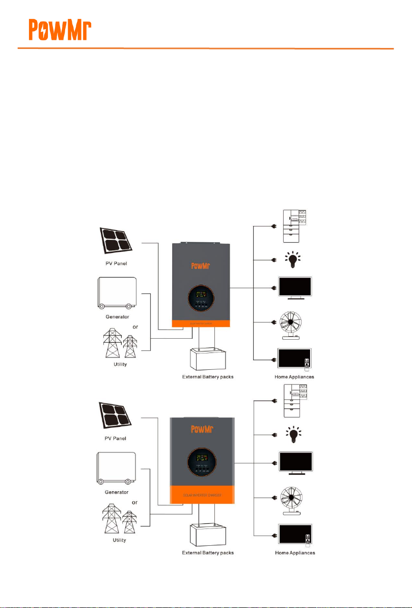
2.2 System Basic Architecture
The following illustration depicts the basic application of the inverter/charger, along with the
additional equipment required to form a complete operational system:
⚫Engine or mains power
⚫Photovoltaic modules
Additional system architectures can be consulted with system integrators based on your
requirements. This inverter can provide power to various electrical appliances in residential or
office environments, including lamps, fans, refrigerators, air conditioners, and other motor-type
appliances.

User Manual
POW-RELAB SERIES
6
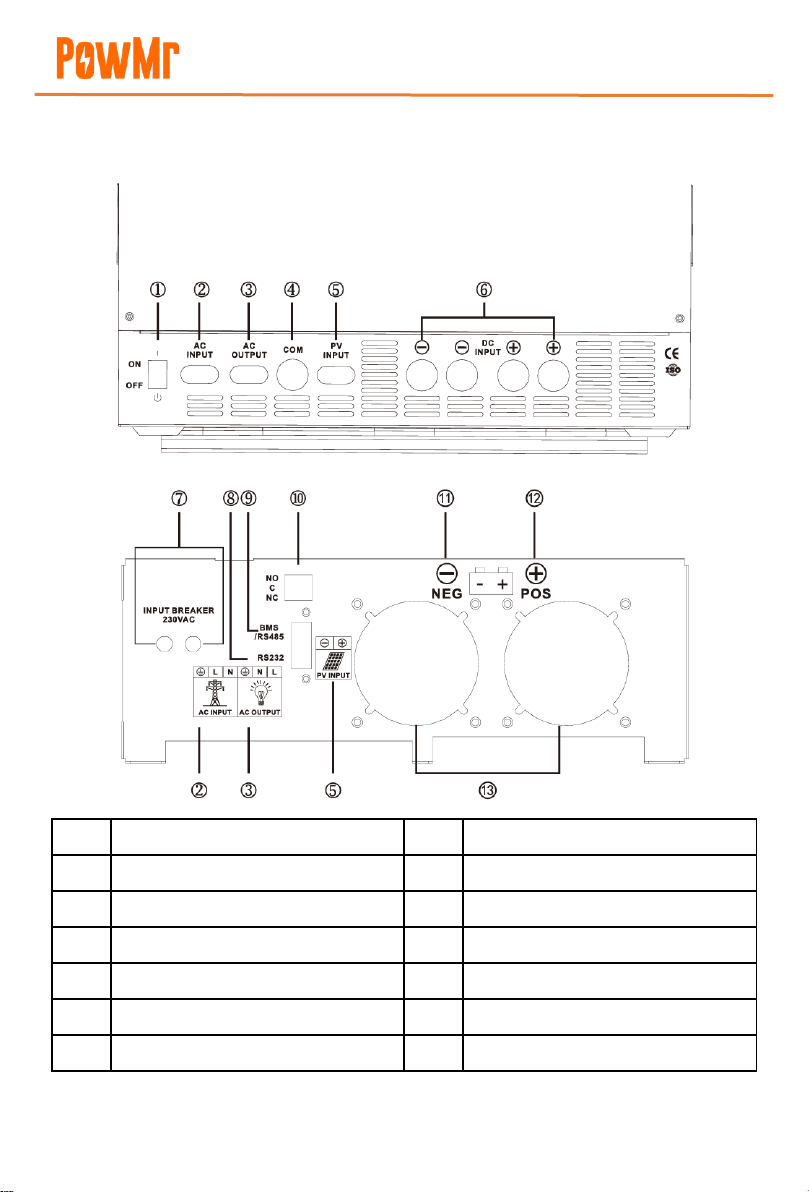
2.3 Product Appearance
2.3.1 3KW Model (POW-RELAB 3KE/ POW-RELAB 3KU)
①
RS232 communication interface
⑦
AC input
②
BMS/RS485 communication interface
⑧
AC output
③
Dry contact ports
⑨
Photovoltaic input
④
Fan
⑩
Battery negative terminal
⑤
Toggle switch
⑪
Battery positive terminal
⑥
Input overcurrent protector
⑫
Battery circuit fuse
User Manual
POW-RELAB SERIES
7
2.3.2 5KW & 10KW Models (POW-RELAB 5KE/ POW-RELAB 5KU/ POW-RELAB
10KE/ POW-RELAB 10KU)
①
Toggle switch
⑧
RS232 communication interface
②
AC input
⑨
BMS/RS485 communication interface
③
AC output
⑩
Dry contact ports
④
Communication port
⑪
Battery negative terminal
⑤
PV input
⑫
Battery positive terminal
⑥
Battery input
⑬
Fan
⑦
Input overcurrent protector

User Manual
POW-RELAB SERIES
8
3Assembly
3.1 Unboxing and Inspection
Before assembly, please inspect the unit to ensure that the items in the packaging are undamaged.
Inside the package, you will find the following items:
⚫Inverter device x1
⚫Instruction manual x1
⚫Explosion screws
⚫Battery fuses
3.2 Installation Tools
Before installation, please prepare the following tools.
Category
Tools
General Tools
Multimeter
Protective gloves
Insulated safety
shoes
Protective clothing
Safety goggles
Antistatic wrist strap
Installation Tools
Electric screwdriver
Socket wrench
Wire stripper
Phillips screwdriver
(M4/M6)
Electric drill
Hammer

User Manual
POW-RELAB SERIES
9
3.3 Equipment Installation
Before selecting an installation location, consider the following points:
⚫Do not install the inverter on combustible building materials.
⚫Install on a solid surface.
⚫Position the inverter at eye level for easy viewing
of the LCD display.
⚫Maintain approximately 20cm spacing on each
side and approximately 50cm spacing above and
below the device for proper air circulation and
heat dissipation.
⚫Ensure ambient temperature remains between
0°C to 55°C for optimal operation.
⚫It is recommended to install the device vertically
against the wall.
⚫Ensure other objects, as shown in the diagram,
maintain sufficient distance from the inverter
surface to ensure adequate heat dissipation and provide enough space for wiring removal.
Suitable for installation on concrete or other non-combustible walls.
Secure the device in place using two screws, preferably M4 or M5 screws.
3.4 Wiring Preparation
Loosen the fixed screws of the wiring terminal cover plate and remove the cover plate.

User Manual
POW-RELAB SERIES
10
4Wiring
4.1 Cable Size and Circuit Breaker Specifications
➢PV IN
The configuration of the photovoltaic input cable depends on the actual power and voltage
parameters of the photovoltaic array.
Required Parameters: Photovoltaic input power, Photovoltaic input voltage
Wire Size Configuration: Photovoltaic input power / Photovoltaic input voltage / 5
For example: If the photovoltaic array has a power of 1600W and a voltage of 144V, the wire
size is calculated as follows:
1600 / 144 / 5 ≈ 2.22mm², so the wire size can be chosen as 3mm².
Circuit Breaker Configuration: Photovoltaic input power / Photovoltaic input voltage
For example: If the photovoltaic array has a power of 1600W and a voltage of 144V, the
circuit breaker specification is calculated as follows:
1600W / 144V ≈ 11.11A, so the circuit breaker can be chosen as a model greater than 11.11A.
➢AC IN
Model
Cable Diameter
Circuit Breaker Spec
220V
110V
220V
110V
3KW
4mm2
10mm2
≥20A
≥35A
5KW
6mm2
16mm2
≥30A
≥60A
10KW
16mm2
25mm2
≥63A
≥125A
➢Battery
Model
Cable Diameter
Circuit Breaker Spec
3KW
25mm2/15mm2 x2
125A
5KW
25mm2/15mm2 x2
125A
10KW
50mm2/25mm2 x2
250A
➢AC OUT
Model
Cable Diameter
Circuit Breaker Spec
220V
110V
220V
110V
3KW
4mm2
6mm2
≥14A
≥28A
5KW
6mm2
10mm2
≥23A
≥46A
10KW
10mm2
25mm2
≥46A
≥91A

User Manual
POW-RELAB SERIES
11
4.2 AC Input & Output Connection
1. Connect the live wire, neutral wire, and ground wire to the respective terminals of the mains
input and AC output as illustrated below, and install circuit breaker protection devices that meet
the requirements on each of the two lines.
2. Ensure proper grounding of the equipment for safety. Ensure all cables are installed correctly
and securely tightened.
AC Input Wiring for 3KW Model:
AC Output Wiring for 3KW Model:
Green & yellow → Ground wire, Blue → Neutral wire, Red → Live
Green & yellow → Ground wire, Blue → Neutral wire, Red → Live

User Manual
POW-RELAB SERIES
12
AC Input Wiring for 5KW/10KW Model:
AC Output Wiring for 5KW/10KW Model:
Green & yellow → Ground wire, Blue → Neutral wire, Red → Live
Green & yellow → Ground wire, Blue → Neutral wire, Red → Live
DANGER
⚫Before connecting the AC input and output, it is essential to open the circuit breaker to
avoid the risk of electric shock. Do not perform any operations while the power is on.
⚫Please ensure that the cables used meet the requirements. Thin or poor-quality cables pose
a serious safety hazard.
User Manual
POW-RELAB SERIES
13
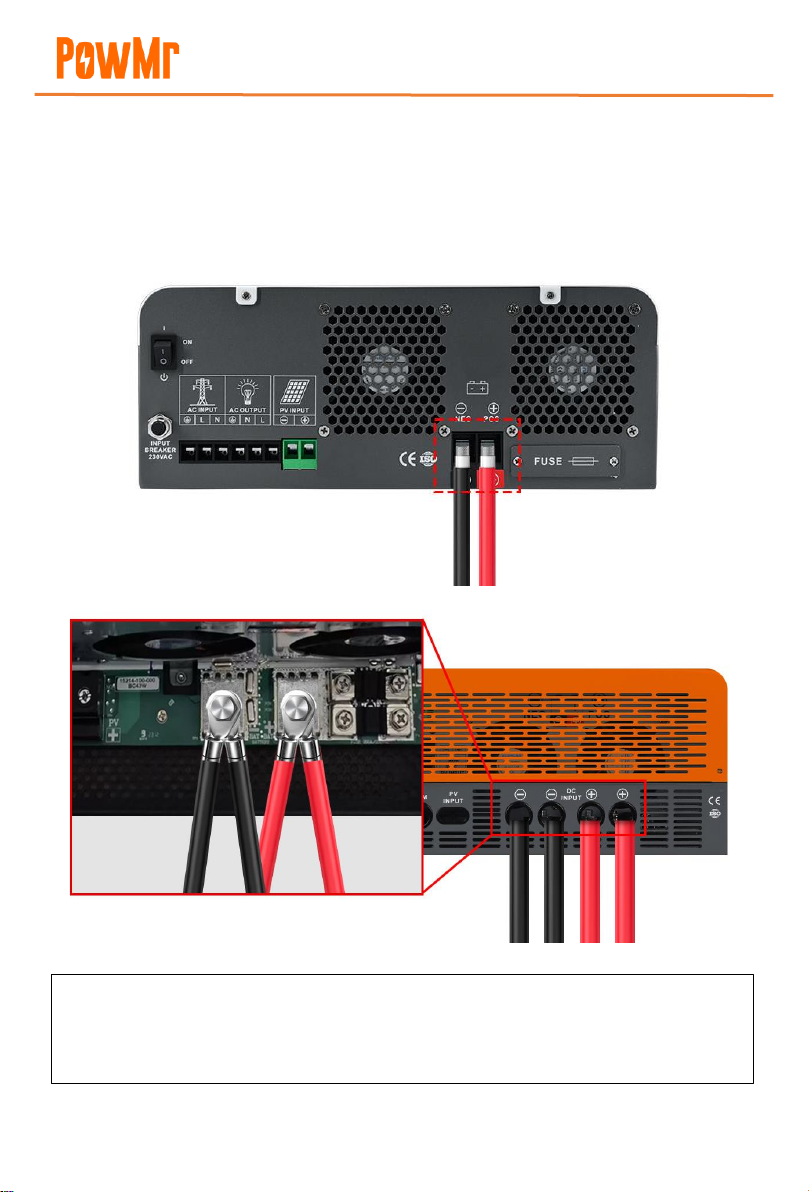
4.3 Battery Connection
Please connect the positive and negative terminals of the battery according to the diagram below.
Be sure to install a circuit breaker that meets the specifications on the battery circuit.
Battery Connection for 3KW Model:
Black→Negative terminal, Red→Positive terminal
Battery Connection for 5KW/10KW Model:
Black→Negative terminal, Red→Positive terminal
ATTENTION
⚫The POW-RELAB series inverters come standard with a fuse device for the battery circuit.
Please use it according to actual needs.

User Manual
POW-RELAB SERIES
14
4.4 Photovoltaic Connection
Please connect the photovoltaic array according to the diagram below, and strictly adhere to the
requirement of installing a circuit breaker that meets the specifications.
DANGER
⚫Before connecting the battery, it is essential to disconnect the circuit breaker to avoid the
risk of electric shock. Do not perform any operations while the power is on.
⚫Ensure that the positive and negative terminals of the battery are correctly connected and
not reversed, as this could damage the inverter.
⚫Please ensure that the cables used meet the requirements. Thin or poor-quality cables
pose a serious safety hazard.
Photovoltaic Connection for 3KW Model:
Photovoltaic Connection for 5KW/10KW Model:
Black→Negative terminal, Red→Positive terminal
Black→Negative terminal, Red→Positive terminal
User Manual
POW-RELAB SERIES
15
4.4.1 Selecting and Configuring Photovoltaic Panels
The following parameters are obtained from the specifications of photovoltaic panels:
⚫Pmax: Maximum output power (W)
⚫Voc: Open-circuit voltage (V)
⚫Isc: Short-circuit current (A)
⚫Vpm: Rated voltage (V)
⚫Ipm: Rated current (A)
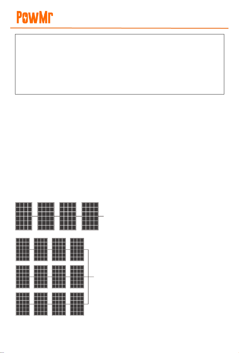
Photovoltaic panels can be connected in series or parallel to obtain the required output voltage
and current to meet the photovoltaic input range allowed by the solar controller and inverter-
charger.
When photovoltaic panels are connected in series, the
total voltage and current are:
Vstring = V1 + V2 + V3 + V4…
Istring = I1 = I2 = I3 = I4 =…
When parallel-connected photovoltaic panels are
connected in parallel, the total voltage and current are:
Vtotal = Vstring1 = Vstring2 = Vstring3 = …
Itotal = Istring1 + Istring2 + Istring3 +…
DANGER
⚫Before connecting the photovoltaic panels, it is essential to open the circuit breaker to
avoid the risk of electric shock. Do not perform any operations while the power is on.
⚫Please ensure that the open-circuit voltage of the connected photovoltaic modules in
series does not exceed the maximum open-circuit voltage of the inverter (which is 150V in
this series), as otherwise, the inverter may be damaged.
User Manual
POW-RELAB SERIES
10
Example: Taking a 48V inverter as an example, selecting suitable photovoltaic components.
Considering two scenarios for the built-in charging module of the inverter: The maximum
photovoltaic input for PWM controller is 105V. The maximum photovoltaic input for MPPT
controller is 150V. The total power should be equal to or slightly greater than 3200W. We can
choose the following specifications for photovoltaic panels:
Maximum power Pmax(W)
80W
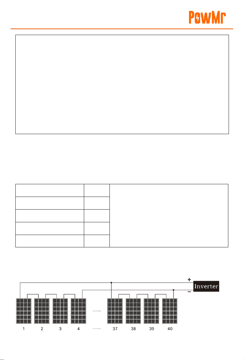
Number of photovoltaic panels in each series:
MPPT→4 panels (421.6V<105V)
MPPT→6 panels (621.6V<150V)
Total number of photovoltaic panels:
40 pieces→3200W/80W: 40 (panels)
Number of parallel-connected groups:
PWM→10 groups (40/4=10 groups)
MPPT→7 groups (40/6=7 groups)
Rated voltage Vpm(V)
18V
Rated current Ipm(A)
4.46A
Open-circuit voltage Voc(V)
21.6V
Short-circuit current Isc(A)
4.8A
Configuration scheme for 48V inverter:
PWM controller: 4 panels of photovoltaic panels are connected in parallel to the inverter, with 10
groups of panels connected in parallel.
⚫In any scenario, the total output power is equal to the power of a single photovoltaic panel
multiplied by the total number of panels. The guideline for configuring photovoltaic panels
is that the total power should be equal to or slightly greater than the maximum allowable
PV power of the solar controller (refer to the technical specifications table). Excess capacity
of photovoltaic panels does not contribute to the capacity of the solar charger; it only leads
to higher installation costs.
⚫The total Ipm of photovoltaic panels should be less than the maximum charging current of
the inverter.
⚫The total Voc of photovoltaic panels should be less than the maximum PV input voltage of
the inverter (refer to the technical specifications table).
User Manual
POW-RELAB SERIES
11
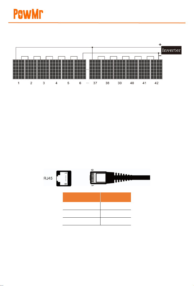
MPPT controller: Every 6 panels of photovoltaic panels are connected in series to form one group,
and 7 groups of photovoltaic panels are connected in parallel.
➢Solar panel daily output = Total power of solar panel x Controller conversion efficiency x Local
average sunlight time.
4.5 Final Assembly
After confirming all connections are accurate and tightened, please reinstall the port protective
cover onto the device.
4.6 Communication Connection
4.6.1 RS485 Connection (BMS Communication)
When connecting the RS485 communication interface externally, the pin definitions are as follows:
Pin
Definition
PIN1
485B
PIN2
485A
PIN3/4/5/6/7/8
NC
This manual suits for next models
5
Table of contents
Other PowMr Batteries Charger manuals


