manuals.online logo
Brands
  1. Home
  2. •
  3. Brands
  4. •
  5. Powrmatic
  6. •
  7. Gas Heater
  8. •
  9. Powrmatic LNVx Series Manual

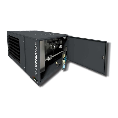
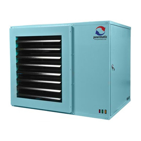
Powrmatic LNVx Series Manual

I INSTRUCTIONS
INSIDE
HEATER MODEL / SIZE
LJ0
(/x-
60
E
SALES ORDER NUMBER
SERIAL NUMBER
POWRMATIC®
Further
information
is
available
from
our
website
www.
powrmatic.co.
uk
..
_.
_.
.ACTIIOl.
...
_
...
,._,
~
'"
!!!~
L.,.J
CJ
....
,
s
---
........
.-
...,g,
I
r
~
~J
TT"P,
-,;
; ,
, . ;. , J
___
__
___
__
____ _
1.
__ '
:::
--- :
::
---
:::==:::==
:::
==:::==
:::
==:::==
:::
==
:::
==
::
:==
:::
==
:::
==
___
__
___
__
___
_J -
--
,...
•
•
r-
---
--
---
--
---
--
---
--
---
-----,
MC200
CONNECTIONS
(to<
VPC)
MCZOO
hMtsrtef CMllne'
UnI1
b=
]
i~··"
l~~~
_i •
1
.]
[111 1
C'
______
-.,
______
_
,
L_.
..
_~
.
~_-=
..
__
...
__
...
__
..
.....
-
...
__
...
__
.
..
_,
•
L...-_
•••
__
•••
__
•••
_
---
-_
...
_-
'=::::~
WIN-,",l.11!1w11'
..
U I
O.Amm
Pu.n.on (FerMIe)
.......
-Loom
Doc Ref: M1041ssue 1.2 Nov
2018
POWRMATIC
·
®
ErP
COMPLIAN
T
SEPlENIER
2018
Certificate Of
Gu
arantee
This
is to certify thatthis heater
is
guaranteed for two
years
parts
and
one
oforiginal commissioning.
The
heater must
be
commissioned within4
To
make
aclaim
In
the first instance
you
mustcontact your
appliance
supplier,
or
ii
n
<"."
,
,,
',,
nrl
pro.
'!.!Jl~
~
1.
The
appliance
type
and
se
ri
al
number
.
2.
The
origi
nal
commissioning documentation.
As
much
d;~if.'~::;;~rm~
3.
Your
supp
li
er.
or
installer, wi
ll
then
contact
~
your
behalf
.
Conditions
of
Guarantee
1.
The
heater
must
have
bee
n
installed
-::;,,~;~~~~
and
in
2,
3,
4.
5.
6.
7.
:.
and
local
regulations.
weeks
of
installati
on.
and a
copy
of
~
~;~;~:i.~
by
a competent and
qual
i
fied
selV
i
cing
<co
.rd'fl,e with
the
manufacturers
ins
truc
tio
ns
.
has
been
used
.
~~~
~~~
~;:r.
~
modifi
cat
i
ons
have
been
made
.
Powrmat
ic'
General
Cond
itions
of
~:r~
j~~:~i~
~~~
Powrmatic
ltd
to
perform
warranty
repa
i
rs
during
the
guarantee
~
li
able
in
respect
of
any
claim
for di
rect
or
i
ndirect
consequentia
l
or
increased
cos
t
aris
i
ng
from
loss
of
use
of
the
heater
,or
any
~~:
?
~~~:;
~
~
~~:k;:~
Ignition
elec
t
rodes,
flame
rectification
electrodes
,
drive
betts,
fusible
i
excluded
from
guarantee
,
9ilwrm"tic
Ltd,
Hort Bridge,lIminster, Somerset,
TA19
9PS
Tel
: 01460 53535
Fax
: 01460 52341
e-mail:[email protected].
uk
Important:This certificate
must
be
kept
with
the appliance
F.lllure
to
provide
.I
copy
of
the
commlsslonlnc
sheet
Inv.llldates
the
heater
wllrrllnty
Con
ten
ts
Users. Installation and Servicing Instructions
CO
NTENTS
Title Section Conten
ts
Page
User Instructions 4
Pre
Installation
1.
1 Introduction 5
Duties 6
Dimensions
7
Options & Accessories 12
1.2
Technical
data 14
1.3
General
Require
m
ents
15
Installation 2.1 Fitting tne unit 19
2.2
Flue
/
Combust
i
on
Air
Duct
System
22
2.3
General
Identificationof Electrical Items 24
2.4 Electrical
Cable
Installation 25
2.5 Wiring Diagrams
28
2.6
Comm
i
ssioning
and
Testing
30
2.7
Servicing
34
Additional
Documents
3.1 Fault
Finding
Flow
Chart
38
3.2 Short Ust of Parts
41
Appendices
Information
required
for
eco
d
es
i
gn
(ErP)
Direct
ive2009/125 43
Warnings
Wh. n workl
n,
on
th
is appliance
the
folowlnc
wam
l
nt_
mustbe ob
..
rwd:
Warnln&::
Hot
5Ufta,
..
Dancer: ElKtrIclty
Wamlnl
: Flammabl. Mat. rlall
Warnlnl:Contai
ns
Mowln, Pa
rts
R
ea
d and underst
ill
d
th
is S.rvlce Manual
Instruc
ti
ons
be
for
e operatlnc
or
se
rvi
dn,
this appliance
User Instructions
If
the h@aterhasnotbeen
left
operational
proceed
as
follows
.
AI
Checks
before
operatin&
the
Air
Heater
The
follow
in
g
prellmlnarv
checks
should
be
made before
lighting
the
heater(sl
aJ
Ensure
that the
ELECTRICAL
supply
to the heaterIS
switched
OFF
.
bl
Check
that
any
warm
alf
del
very
outlets are open.
c)
Check
thatthe thermostat
Is
set.
d)
Che<k
that
the
clock
control
is
set to
an
ON
perIOd
e)
Check
that
any
other controls are
calling
for
heat.
BI
Operatin&
the
Air
Heater
1.
SWitch
on
the electrical supplv at the Isolator
2.
If the
Red
lim
it
in<hcator
lamp
IS
illuminated,
identJfy
the l
imit
stat
, remove the
black
cap and press the reset
button.
3.
The
startup
sequent!!
wiN
commence. After ashort
delay
the
burners
wd
lltghtand the green 'ON' indicator on
the frontof the heater
Will
be
illuminated.
4.
lf
the Dume!s
fal
to light the control box will
automatJeaJly
restartt
he
Ignition
sequence
.Ifafter5
attempts at
igni
tion the burners
have
stit! fail
ed
to light
the control
box
will
go
to lockout
and
the
Amber
lockout
lamp
on
the front of the heater
(or
on
the low level remote
reset,
or
M(200/M(300
iffitted)
win
be
illuminated.
To
restartthe ignition
sequence
depress
the reset button
on
thelow level reset for
abO\Jt
1 ~
2
seconds
.
WARNING
:
If
It
II
not
polilble to II,ht the
heate,
afte,
leveral
attemptl,
contact
the
Installe,
or
Iocallervlce company.
CI
To
Shut
Down
the
Air
Heater
1)
For StMHt Perlodl:
Turn
the
room
thermostat to the
OFF
,or set to 'Summer
Mode'.
Complete
smp
1
above.
Wait for 5minutes
and
then tum
OFF
the electrical
sup
plV
at
the isolator.
DI
Description
of
Operation
Importilnt: The
huter
must
NOT
be
controlled
by
swltchlnc
ON
and
OFF
the
mil
ln electrlcil! supplV to tt.
1)
Standilrd Units
The
ignition
sequence
commences
each
time the
elCternal
controls
e.g.
time
clock
,
room
thermostat, controller etc.
call
for heat.
The
int
ernal
exha
ust fan will
run
and.
when
5I.Ifficient
com
bustion airflow
Is
proved
by
the air pre
ssure
switch. the Ignition spark wtll
be
get\erated, the main
gas
valve
opens
and
the
burners will l
igh
t
on
HIGH
FIRE
for the first30
seconds
Irrespective ofthe requirements
ofthe external control.
The
green
'ON'lndicatorwill
be
Inumlnated.
The
heaterfan will automatically start
30
seconds
after the burners l
ig
ht
Afterthe first
30
seconds
,
the heat
ou
tput will then
be
con
t
ro
ll
ed
eitherto
high
fire
or
low fire depending
on
the requirements of the
space
being
heat~
and the
~ternal
controls fitted.
When
the
external controls
are
satisfied the burners will
be
turt\ed
off
and
2~
minutes
la
ter t
he
healer fan
wiH
automatically
stop. If the burners fall to light the contr
ol
box
will
make
another four attempts at Ignition before
going
into bumer
lockout.
The
amber
'Loc
kout' Indicator/reset switch will
be
Illuminated.
2) Modulatln, Units
When
the burners
are
alight,the heat outputwill
be
co
ntrolled to
any
point between
high
and
low fire;
depending
on
the requirements ofthe
space
being
heated
and
the external contr
ols
fitted.
11
Summer I Winter Model
Certain types of external controls will provide for two
modes of operation
i.e:
Summer:
The
heater fan
alone
will run at the dictate 01
the external controls toprovide air movement.
Winter:
The
heaterwill operate normally.
.)
Oveme"tThermostat
This
operates
if
high temperatures within the heater
are
detKted.the burt\ers
are
tutt\ed off
and
a
Red
Indicator
lamp
on
the front
pa
n
el
is
Illuminated.
LNVIC15·
70 units
have
asingle thermostat
located
Inside
t
he
healer.
LNVx35
&
90·140
units
have
an
additional thermostat
on
the
side
of the unit at the opposite
end
to the
controls (eit
he
r thermostat
can
go
to limit
and
shut off
the burners).
The
faultcondition must be Identified
and
rectified
and
the thermostat
manua
llyreset
via
the
red
high
limitreset switch.
When
the:
unit
has
cooled.
identify
the lim
it
stat,
rem
ove
the
black
cap
and
press the
re
se
t
button.
The
red
indicatorlamp will
go
out
and
the unit
is
operational
again
.
Note: The
limit
tne
rmostat(s) can
on
lvbe reset
once the unit has cooled down. Unless the
cause of t
he
f
au
lt
co
n
di
t
ion
is
readilyobvious,
for example a power
(ut
whitst
the heater was
operati
ng
.aservice
en
g
in
eer
shou
ldbecontacted.
E)
Maintenance
To
maintain efficient, reliableand safe operation
of
the
heater
It
must
serviced annually
bV
a qualified person,
F)
IMPORTANT
Free access must
be
maintained to and around the heater
for servicing purposes and the air supply
to
the heater
must not
be
restricted
in
any
way
.Combustible materials
must not
be
stored adjacent to the heater.
If at any time a gas l
eak
is
suspected, turn
OFF
the
gas
supply at the meter and contact the
local
gas undertaking
Immediately.
The
lNVl(
range are
high
lyefficient, gas
fi
r
ed,
fanned
ctrC\Jlatlon
air heaters thatcover heat outputs
of
15kW
to
140kW,
have a closed combustion
circuit
and are supplied
complete with a nue system.
lNVl(
heatersare certified
for
use
on
Natural
Gas,
Group
H-
G20
·.
Appliance
Categories are
Cat
112H
1GB,
IE).
All
lNV)(
heaters are
CE
certified and conform to
all
the
EUropean
directives stated
In
section
1.3.1
l
NVl(
heaters are designed to
be
suspended
fr
om suitable
roof points or a1ternativelvto
be
mounted
on
pur
pose
designed brackets and are intended
primarily
for heattng
commercial or
IndustriaJ
premtses.
All
variants are for
internal use
on
ly.
lNVl(
Maters feature a closed
combustJOrt
cIrcuit
and
have an internal eKhaust
fan,
mounted downstream
of
the heilt
el(changer,
to evacuilte t
ile
products
of
combustion and draw
in
air for combustion.
The
air
heater
must
be
connected to a flue system that
is
approved
by
Powrmatlc Ltd.
lNVl(
heaters
may
be used where the atmosphere inside
the premises
could
be
contaminated
e.g.
Dust,
oil
mist
etc. butthe heaters are not
ai
rtight and therefore
may
not
be
used
in
areas cl
aSSIfied
as
hazardous
as
defined
in
as
5345: Part 2 or areas subjectedto significant negative
pressures due to el(tract systems,
Use
r Instructions
All
Powrmat
lc
heaters use gas and electricity to
power
them, they
may
also contain
movmg
parts such as
pulley
s
and belts. It
wou
ld
be
hazardous to tamper with or
attempt to service
un
less
you
are a competent pluson
in
the
field
of
Gas
and Electri
cal
work
.
If
you
have any safety questions reference the servicing
and installation
of
any
of
our heaters please
do
not
hesitate to contact
our
head office
for
el(pert
advice
.
Your
safety
Is
paramountto us.
Gas
Safety (Installation.
Un'
(Amendment)
Aeculations
2018
It
Is
~w that
all
cas appliances arelnst;aJled,
adJustltd and, If n.cessary,
conv.rt.d
by
quallflltd p.rson
s'"
In
accordance wtth the
curr.nt 'SIU. of the above reculatlons.
Fallur. to Inltall appil
anc.I
corr.ctly can lead
to
prosKution.
It
II
In
your own I
nt.r
.sts
a
nd
that of safety
to
.nlur.
that thalaw Is compllltd w
fth
.
•
Gas
Safe Register@dEnglneer
1.1
Introduction
lNVl(
F,
lNVl(
Duo
and
lNVl(
Vheaters
have
an
axial
fan
assemblyfitted to circulate the
aJr
being heated through
the formed tube heat exchanger.
lNVl(
cn
units are
supplied with a centrifugal fan and
lNVl(
0 units
for
use
with ducted systems where the air
moving
fan
is
by
others
or
a centrifugalfan section
Is
used adjacent to or
remote
from
the heater.lNVl(
OH
units are for use
in
air
handling units.
Heaters are fitted
as
standard with
Ins
hot burners, a
fully
automatic control
for
igniti
on,
fl
2lme
sen
sing.
gas supp
ly
control and
sa
fety functions,
an
internal e)(haust r
an,
main air fan
IF
and
CCF
models!,
and fan/limit thermostat.
Options
include
High/low or Modutating burner controls,
inlet duct connection, outlet duct connection. 30-, 45-
head,
90
-outlet bend, vertIcal/horizontal outlet louvre
assembly and a full range
of
modular duct components.
IMPOATANT
SaNk'
and
Ma
l
nt.n
.
nce
[nc
l
nurs
shan
ensure that replacemant
It.ms
are fitted,
adjusted and sat
In
accordance wtth tha
data and d.tall
set
out
In
thasa Inltructlons.
If
In doubt
conlult Powrmatk
Techn
ical Dapartment.
•
LPG
conllefSion
/tits
available.
Technica
l
Specificati
on
LNVx
~
~,.......
""
••
,,,
""
".
'"
'"
'"
,..
,,.
'"
""
9H
'f"""""
..
'"
"" ""
,,,.
,." .
""
""
'5" I
""
""
I
""
'
"''
""
..
K<>N
~~
J""
m"
'"
'50
,."
",
,,,
'"
'"
un
'"
,..
'-"
'"
'I
w~
l-
"""
m
...
, "
'"
,.,
30.'
'"
".,
'"'
~
.,
-"'-
....
I
t;.
U""C~
-';;-Uo
'"
'
~
,
'"
'
,;0
-
.
'
",
'
~
,>:!,
,
~
__... _
""
"'
_
""'"
'"'"
""""
,,",w.
I""'"
""
~
,..
'"
,.
, I '" "" '"
os,
'-'" I uo I
'" '"
."
"""
"'"
cc,
1-
"'"
1=
....
~.-..- ,
..
"
'"
,
..
I
'"
."
'"
...
I
."
I
""
,,
~
""
"""'''''''
" ,
-,,-
:;'"
Crou'"
"..,
""""'"
.'"
~""
""
'"
'"
no
""
...
'" ' "
'"
",
""
,
:::-.~
""'"
"'"'"
_.
~,
""
...
." ."
."
".
" .
'"
.'s
...
'"
."
I
~~·
I
""'"
I
'"
m "
.
Dimensio
ns
LNVx
F-
FreeblowlIlg
-\
"I
~
,
.-
--
lNVxl'l.mgl' U')PfS
1"~'llh'ton&S(rV{nl"
t
J'
I)
<'
/1 " I I
Dimensions
LNVx
Duo-
AXia
l
Fan
BI-dlrectlonal Units
R
om
'"
-
00
~
""
,
om
" ,
om
'"
G
H
..,..
'"
~
27.
~
"
"
~
'"
p
om
'"
'"
''''
"
'22
'"
60,
'"
"'"
'"
'"
."
''''
3315
78
7
'"
,
27.
"'"
'"
'"
Dime
nsions
LNVx
V-
AX
i
al
Fan
Downflow
...
~.
~
--..,
INVJ~ao,l'
LJ",{'rsl!\~tJjlt'on&C,
"n'
'r·
,
I,
I 1 I
Dimensions
LNVx
CCF-
Cenlrlfugal
Close
Coupled
Fan
Units
Sll.~"~TSM10
Dimensions
LNVx
D
Dueled
Heal Module
(No
fan)
~--
,~
~.
I NVx
R.lflg~
lkl'rs
In~tlll"tlon
&
\~"
(r
I
••
Ie
I •
'1,
r I
Heater
Op
tio
ns
Mixing
Bo)( -(LNVx (CF Models
On
I
V)
..
Fan Plenum
80x
-
(LNVx
eCF
Models
Onty)
Accessories
30"
OownfJaw Head -
(LNVx
F
Model
s
Only)
goo
Oownflow
Head
-(lNVx
(CF
Models
Onty)
I
I
,
Filter
Bo)(
-
ILNVx
((F
Models
Only)
Vertical Louvres
(For
Use
On
All
Models)
r--
'-
Acce
sso
ries
Swivel Wall Bracket - I
LNV,
F
Mod.ls
Onlvl
Cantilever Wall
Brac
ket -
(LNVx
FModels
Onlv)
Not~
-
DImensIons
for
the
SWIVel
and
(anulever
brackets
reman
thE'
sam£'
for
aIIlNVx
mod",
-
SWIVel
Brackets
can
not
be
used
WIth
dolble
lOts
"r.!~
"-I
LN\I'~Jng~
JSPt~I"'tllll
t
f()"',
'f,
" '
J'
,
!,
r
1.2 Technical Data
Injector Sizes &
Bumer
Pressures -Natural
Gas
-Group H - G20
Net
(V
(H
i =34.02MJ/m')
Nominal Inlet
Pre
ss
ure . 20mbar
M
inimum
Inlet
Pressure ., 17.5mbar
1.3 General Requirements
1.3.1. Related Documents
AlIlNVx
heat
er
s
compl
V
wIth
the follow
in
gEuropean
Directives'
EntrlV Re
la
ted Product Directive:
Gas
Ap
pliann
Dired
ive
:
E
lec
tr
om
agnet
ic
Compatibility Directive:
lo
w Vo
lt
age
Di
rective:
M
ac
hl
n.
ry
Di
rec
ti
ve:
2oo9/125/
£C"
200
9/1 4
2/£(
2
004
/108/£(
2006
1951
£(
20
06/421
E(
Air heater(sl must
be
Installed In
accordance
with 85
62
30
and
855440 pl
us
any
re
levant requirements of l
ocal
and
national
bUilding
codes
. •
wh~~
appropriate
.
1.3.2 Location
Powrmatlc
lNVx
units
ar£'
deSIgned
to
opt-rate withl"
an
ambient temperature range
of
·10 to 25-C
LNVx
heaters can be installed
in
several ways: i)
suspended
from 'drop rods'via purpose designed
M10
suspenslon fhdnl points
on
the healer, I
i)
attached
to
our
optional
walt
support brackets
or
Hi}
positioned
on
al
evel.
non-combustible
base.
In all
cases
,it
is
importantthat all
supporting structures
have
been
assessed
withregard to
the relevant weight loadings.
Coosideration
should
be
given to flue routes
and
points of
exit,
gas,
electrical
and
(ontrol connmions.ConsideratIon
should
also
be
given to the throw characteristics of the
heater,issues of
pub
l
ic
access
and
siting of environmental
control stations andlor remote temperature sensors
where the position n
eeds
to
be
representative of the
zone
temperature to which they refer.
Where
the location ofthe
ai
r
hea
t
er
is
such
that itmight
suffer external mechanical damage
e.g
.from overhead
cranes
,fork hft trucks,
it
must
be
suita
bl
y protected,
Heaters
should
not
be
install
ed
in
hazardous
areas
or
areas
where there
is
aforeseeable fisk offlammable
or
corrosion Inducing particies,
gases
orvapours
being
drawn into the combustion airormain fan
circu
its.
Areas
where
specjaj
consideration or
advice
may
be
required
could
include but
is
notlimited to -
Where
de-greasing solvents
are
present,
even
In
minute concentrations
Where
paint spraying
is
cartled out
Where
styrenes or other laminating products
are
used
Where
airborne silicone
is
present
Where
petrol
engine
vehicles
are
stored
or
maintained
Where
dust
Is
present
(Le.
wood worki
ng
or
joinery
shops)
Where
high
le
vel
s
of
(,lCtract
persist
In
stallat
IO
n
In
suc
hareas
may
be
poSSI
ble
under spe
CIfi
c
c
ondI
tIons.
Plea
se
cons
u
lt
our
Techn
IC
al
Department for
furt
he
r informatio
n.
1.3.2.1 Sizing of
th
e
heater
The
heater s
hould
be
correctly
sized
for the ar
ea
that it is
heating,
Full
calculatIons
need
to
be
preformed to
ensure
the correct
KW
output heater
is
fitted
{CiBSE
elemental
methodology
can
be
used
,or the Powrmatic
Technical
Department
can
provide guidelines}.
1.3.3 Electrical Supply
Wiring external to the air heater must
bl!
Installed In
ac
cordance
with the I.
E.E
.Regulations for Electrical
Installations
and
any
local
rl!gulatJons which apply.
All
standard heaters
are
supplied
by
230V
-1
ph,
50Hz.
The
method of connectIon to the main electricitv supply
must:-
-facliitate the complete electrIcal isotation of the unit(s}
via
asuitable fused isolator
(see
section 2.4.5 for ratings)
-be
in
a
readi
ly
accessible
position adjacent to the unit(s)
-
serve
oNy the
UM(S}
-
have
acontact separation ofat least
3mm
in
all
poles
.
See
the
accompa
nyi
ng
wiring diagram for the heater
electrical connections
lNVx
(CF
and
fan/s~encer
units
can
also
be
supplied for
400V
3N,
50Hz
,
1.3.4 Gas Supply
Aservicing valve
and
union
to facilitate servicing must
be
fitted to the
gas
I
nl
et
pipe work of the heater.
The
gas
supply
must
be
completed
In
so
l
id
pIpe
work
and
be
adequately supported.
Heaters
suspended
by
drop rods,straps or
cha
i
ns
must
have
a
fleX
I
ble
connection
as
the final link between the
gas
supplV
pipe
work
and
the heater.Sufficient
sla
ck
must
be
left
In
the connection to take account of normal
movement ofthe heater.
WARNING:When compleUnc
the
final
ps
connection
to
the
heate, do not
piau
undul
strain
on
the
ps
pipe
work
of
the
heater.
1.3.4.1 Service Pipes
The
l
oca
l
gas
undertaking
shou
ld
be
consulted
at
the
i
ns
tallation pl
anning
stage
in
order toestablish the
availability of
an
adequate supply of
gas
to suitthe
1I!!.'if~
•
.:'
(NV,R,)nl':rl)~f'>I"~IJIl,}tI3,&,>'r
I
I",'
,
'1
I I J
1.3 General Require
ments
bUilding
requirements.
An
existmg
service pipe
must
not
be used
wit
hou
t
prior
consultation
with
the l
oc
al
gas
undertaking.
1.3.4.2 Meters
An
existing meter should
be
checked,
preferably
bV
the
gas
undertaking. to
ensure
that
the meter
is
adequate
to deal with the total rate of gas supplv required
bVall
connected equipment.
1.3.4.3. Installation Pipes
Installation
pipes should be fi
tted
In
accordance
with
I
GEI
UP/2
Pipe
work from the
meter
to the air
heater
must
be
of
adequate
sin.
Do not
use
pipes
of a
smalll?f
size
than the Inlet
gas
connection
of
the heater.
The
complete Installation must
be
tested for soundness
as
ducribed
in
the
above Code.
1.3.5 Flue System
Onlv
flue
5vstl!mS supplied
through
Powrmatic
ltd
may
be used
with
lNVx
units
. Several
configurations
of
flue
and
combustion
air
du(.ts are
avaUable
.
The
flue
must terminate
In
a freelvexposed
pOSition
and
be
Sited
to prevent the products
of
combustion entering
any
opening
In
a
building
msuch concentration
as
to
be
prejudicial
to health or a nuisance.
TVpe
B22lnstaUation.
"
Type
C12
or
(32
Installation.
1.3.6 Ventilation Requirem
ents
Type Bflued
Inst~lI~tlons
.
Where
lNVx
heaters are Installed within the heated
space
lie
not
in
a plant room or
an
enclosure) and
having
a
bUIlding
deSIgn
air
change rate
of
greaterthan
D.5/h
.
additional
proviSion
for
ven
tilation
Is
not required.
If
the
bllllding
deSIgn
air
changE'
tate
is
less than
D.5/h
,
additional
proviSion
for
natural
or
mechanical ventilation
is
required.These
being:
•
Natu
ral
Ventilation:
Gr
i
lles
having
a free area
of
al least 2cm'
per
kW
of rated
heat input shall
be
provided
at
low
levell.e.
below
the
level
of
the heaterflue connection.
• Mech
anical
Ventilation:
Must ensurethat
the
space air change rate
is
at least
D.5/h.
must be
of
the 'input' type and interlocked to
ensure the heaters cannot
work
If
the input system
Is
not
warMing
Type Bflued Installations.
Where
lNVx
heaters are Installed In a plant room or
an
IInclosur.II.
•.
not within the
huted
spac.)
having
combustion air drawn
direc
tl
yfrom the
room
and
connected to a
flue
thatevacuates the products of
combustion dlrectlv
from
the room additional
provision
for
natural or mechanical ventilation
15
required.
•
•
Natural
Ventilation:
There
must
be
permanentair v
ent
scommunicating
directly with the outs
ide
air,
at
hi
gh
l
ellel
and
at
low
level.
Plant Rooms
l
ow
lellel
(in
l
et)
4cm'!kw of total rated net heat Input
High level (outlet)
2cm"kw
of
tota
l rated
net
h
eat
input
Endosures
Low
level
(inlet)
lOcm'/kw
at
total rated netheat input
High level (outlet)
Scm"kw
of total rated
net
heat Input
• Mechanical Ventilation:
The
minimum
fl
ow
rate
of
ventilation shall be 4.1
4m'/h
per
ki
l
owat
t of
tota
l
rated
heat
input
.
Type
( flued installations.
Whe
re
lNVx
heaters i re Installed within the
hnted
span
(
I.e.
not In a plant room or an
MClo5ure)
having
combustion air dueted to
the:
appliance and combustion
1.3 General Require
ments
prod
ucts
dueled
to
the
outSide .ur,
NO
additional
provision for the
supplV
of either
co
mbustion air or for
combustIon products dilutlon or additional provision for
the sup
plV
of aIr
is
necessary.
Type
C
f1ued
Installations.
Where
lNVx
heaters are Installed
In
a plant room or
an enclosure
(I.e
. not withIn the heated space) having
combustion air
due
ted to the appliance and combustion
products
ducte<!
to theoutside,
il
lr vents shilll be
provided
ilnd
be permilnentlv open.
To
room orIntarnal space
low
levellinletl 10cm'/kw
of
total rated net heat
inpu
t
High
level(outlet) 10crn'/kw of totalrated net heat
Input
Direct
to
outside
air
low
level (inletl5cm'/kw of total fated net heat input
Hi
gh
level (outlet) 5c.m'/kw
of
total rated net heat inpul
~-.
~T-
UOV.Rd'1/;,
U~U<
1'~
'
111'[)
8.
(.[0,
t " I
'I
r
1.3
Gene
ral Require
ments
1.3.7 Air Distrib
ution
5vstQm
Where
lNVx
F
uruts
arl!
required
to
cover
a large
floor
area,
and
in
bu
ildings
with
high roof
01
ceiling
heights
Calecon
thermal economiset
Units
may
be considered to
ensure even heat distribution and minimise stratIficatIOn.
(are
should be taken
to
avoid Impeding the air
throw
with
tacking, partitions. plant
or
machinery etc. Various
outlet
configurations are available
as
optiOnal
extras
to
mOdify
the
ai
r throw pattern
to
suit
partJcular
site conditions.
~or
lNVx
CCF
units,
1M
dun
work
must comply to current
regul
ations
and
be
correctly caiculated to match
the
particular
heaters
fesistance and air flow.
Afu
ll
and
unobstructed
return air path to
the
air heater(sJ
must
be provided.
1.3.7.1 Ducting RequiremQnts
If
the
an
heater(s) arl! Installed
In
iI
plant room, the return
air
Intak@(s)andth@warmalr outl@tls)fromthe
heat@r(s)
must
b@fullvducted
,ln
toandoutofth@plan
t
roomto
aVOid
Interf@rencewlth the operation
of
the heater
The openings In the structure
of
the plant room/enclosure
through which
the
dueting passes
must
be fire stopped.
(are
must
be taken
to
ensure
that
return-arr Intakes are
kept clear
of
sour
ces
of
smells and fumes, and where
there
is
any possibili
ty
of
pollution
of
the air
bV
dust,
shavings etc
.,
precautkms
must
be
taken to prevent
contamination.
If necessary, suitable barrier railsshould be provided
to
preventany combustible material being
plac~
within
900mm
of
the
outlets

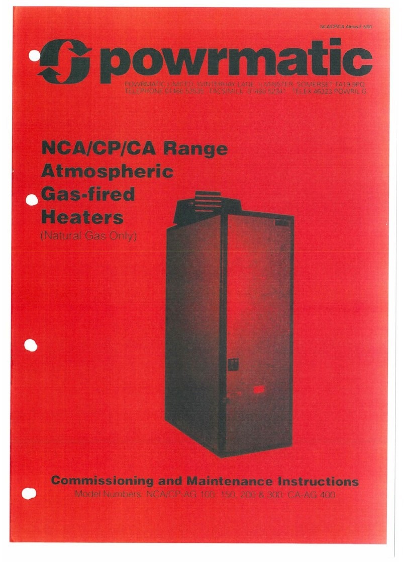
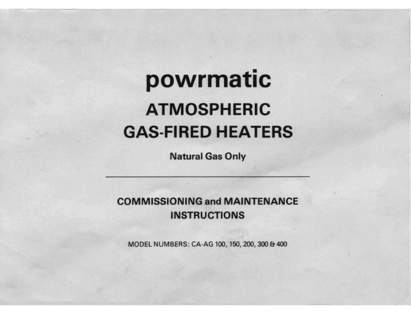
This manual suits for next models

12

Other Powrmatic Gas Heater manuals

Powrmatic NVx10 Manual

Powrmatic

Powrmatic NVx10 Manual

Powrmatic NCA series User manual

Powrmatic

Powrmatic NCA series User manual

Powrmatic CA-G series User manual

Powrmatic

Powrmatic CA-G series User manual

Powrmatic VPC 130 Manual

Powrmatic

Powrmatic VPC 130 Manual

Powrmatic VPC Series User guide

Powrmatic

Powrmatic VPC Series User guide

Powrmatic TE Series User guide

Powrmatic

Powrmatic TE Series User guide

Powrmatic LNVx F Series User guide

Powrmatic

Powrmatic LNVx F Series User guide

Powrmatic ErP NVS 30 User guide

Powrmatic

Powrmatic ErP NVS 30 User guide

Powrmatic CA-AG 100 Technical specifications

Powrmatic

Powrmatic CA-AG 100 Technical specifications

Powrmatic CP series Manual

Powrmatic

Powrmatic CP series Manual

Popular Gas Heater manuals by other brands

Truma VarioHeat eco AU installation instructions

Truma

Truma VarioHeat eco AU installation instructions

Yunca Gas jervois Operation, maintenance and warranty manual

Yunca Gas

Yunca Gas jervois Operation, maintenance and warranty manual

Comfortflame CCL3924NRA owner's manual

Comfortflame

Comfortflame CCL3924NRA owner's manual

ReddyHeater BWH10NLMB OWNER'S OPERATION AND INSTALLATION MANUAL

ReddyHeater

ReddyHeater BWH10NLMB OWNER'S OPERATION AND INSTALLATION MANUAL

Listen Technologies LT-700-150 user manual

Listen Technologies

Listen Technologies LT-700-150 user manual

Desa CF18PV Owner's operating & installation manual

Desa

Desa CF18PV Owner's operating & installation manual

SYSTEL SunPower 65 Usage notice

SYSTEL

SYSTEL SunPower 65 Usage notice

Burley G4121 mk2 Installation & user's instructions

Burley

Burley G4121 mk2 Installation & user's instructions

Kingsman GLVF24MAN OWNER'S OPERATION AND INSTALLATION MANUAL

Kingsman

Kingsman GLVF24MAN OWNER'S OPERATION AND INSTALLATION MANUAL

Italkero Eco SC Series Installation and After-Sales Service

Italkero

Italkero Eco SC Series Installation and After-Sales Service

Sunbeam SOF1000-CN Instruction leaflet

Sunbeam

Sunbeam SOF1000-CN Instruction leaflet

Superior TF18NV Installation and operation instructions

Superior

Superior TF18NV Installation and operation instructions

Carrier 48GS Guide Operating and maintaining guide

Carrier

Carrier 48GS Guide Operating and maintaining guide

Desa R OWNER'S OPERATION AND INSTALLATION MANUAL

Desa

Desa R OWNER'S OPERATION AND INSTALLATION MANUAL

Rinnai Brivis CC315 Series installation manual

Rinnai

Rinnai Brivis CC315 Series installation manual

Magiglo EMPATHY 16" Installation, servicing  & user instructions

Magiglo

Magiglo EMPATHY 16" Installation, servicing & user instructions

Reznor CD2 Installation

Reznor

Reznor CD2 Installation

Vermont Castings 3095 Homeowner's installation and operating manual

Vermont Castings

Vermont Castings 3095 Homeowner's installation and operating manual

manuals.online logo
manuals.online logoBrands
  • About & Mission
  • Contact us
  • Privacy Policy
  • Terms and Conditions

Copyright 2025 Manuals.Online. All Rights Reserved.