by carefully positioning return air intakes and by the
provisionofscreenstopreventcontamination.
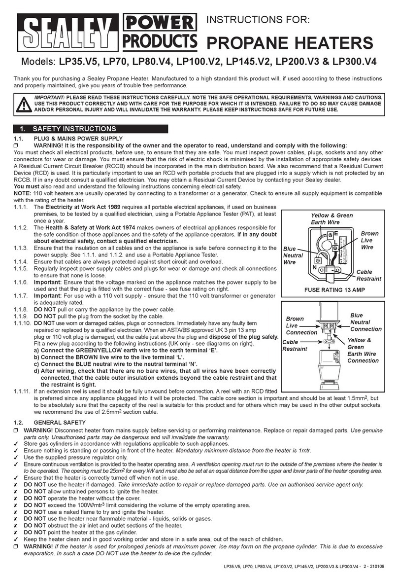
3.7 Electrical Supply
Wiring external to the air heater must be installed in
accordance with the I.E.E. Regulations for Electrical
Installationsandany local regulations which apply. Wiring
should be completed in flexible conduit.
TEheatersrequirea400V-3N,50Hzsupply.The method
of connection to the main electricity supply must facilitate
thecompleteelectricalisolationoftheairheater(s)andthe
supply should serve only the air heater(s).
Theisolatormusthaveacontactseparationofatleast3mm
in all poles. The method of connection should be provided
adjacenttotheairheater(s)inareadilyaccessibleposition.
See the accompanying wiring diagram for the heater
electrical connections.
4. Installation of Air Heater(s)
4.1General
Before installation, check that the local distribution
conditions, nature of gas and pressure, and adjust-
ment of the appliance are compatible.
The air heater must be installed in accordance with the
rules in force and the relevant requirements of any fire
regulations or insurance company’s requirements
appertaining to the area in which the heater is located,
particularlywherespecialrisksareinvolvedsuchasareas
wherepetrolvehiclesarehoused,wherecellulosespraying
is carried out, in wood working departments etc.
Whichever method of mounting the air heater is used the
followingminimumclearancesforinstallationandservicing
mustbeobserved.
Tothe front 1.0m
To the rear The depth of the heater
To the side 1.0m
Abovetheheater 1.0m
Anycombustiblematerialadjacenttotheairheaterandthe
fluesystemmustbesoplacedorshieldedastoensurethat
its temperature does not exceed 65 °C.
IMPORTANT:
1.Noairheatershallbeinstalledwherethereisaforeseeable
risk of flammable particles, gases vapours or corrosion
inducing gases or vapours being drawn into either the
heated air stream or the air for combustion. In such cases
installationmayonlyproceediftheairtobeheatedandthe
air for combustion are ducted to the heater from an
uncontaminatedsourcepreferablyoutsidethe building. In
certainsituationswhereonlyairborneparticlesarepresent
itmay suffice to fit filters on the air inletducts of the heater.
AdviceintheseinstancesmaybeobtainedfromPowrmatic
Ltd.
4.2Installation
TEheaterinstallationmayonlybecompletedbyPowrmatic
Ltdor their appointedrepresentatives.
The heaters must be installed on a level noncombustible
floor capable of supporting the weight of the heater.
4.3 Flue System
ATeepieceissuppliedwitheachheaterandmustbefitted
totheflueoutletsocketontheheater.Thefluesystemthen
connects directly on to the tee. For flue sizes refer to Data
Sheet.Allunitsmustbefittedwitha fluehavingaminimum
height,fromtheheatertotheflueterminal,of2m.Horizontal
runs of flue are not permitted unless they are adequately
compensated by associated vertical sections.
If necessary a single offset using two 45° bends can be
included to avoid obstructions. The maximum equivalent
resistance of the flue system must not exceed 30pa.
Details of how to calculate the resistance of the flue to be
installed are given in Appendix A.
4.4 Condensate Drainage
Thedesignofthefluesystemshouldminimisetheformation
of condensation, however when this is envisaged to be a
problemprovisionshouldbemadeforcondensationtoflow
to a joint where it can be drained, preferably into a gully.
4.5 Gas Connection
Aservicing valve and downstream union must be fitted at
theinlettotheairheatergascontrolsassemblytofacilitate
servicing. The gas supply to the air heater must be
completedinsolidpipeworkandbeadequatelysupported.
WARNING
Whencompletingthefinal gasconnectiontotheheater do
not place undue strain on the gas pipework of the heater.
4.6 Electrical Connections
Allunitsarefullypre-wiredandonlyrequirefinalconnections
for the incoming mains supply and, if required by the
specification, completion of any external control circuits
e.g. via a room thermostat, time clock etc. The electrical
supplymustbe run toapointadjacent to theheaterandbe
suitably terminated to provide an isolation point that will
prevent remote activation of the unit during servicing. The
heater electrical panel is located at the front of the heater
and cable entry points are provided in the adjacent heater
framework.Referencemustbemadetotheencloseddata
sheettoascertain theelectricalloadingof the airheater(s)
being installed so that cables of adequate cross-sectional
area to safely carry that load are used for the electrical
installation.Thelengthoftheconductorsbetweenthecord
anchorageandtheterminalsmustbesuchthatthecurrent
carryingconductorsbecometautbeforetheearthconductor
if the cable or cord slips out of the cord anchorage. All
external controls must be of an approved type.
See the wiring diagram accompanying these instructions.
5. Control Thermostat Siting
If the specification requires a remotely mounted control
thermostat it should be fitted at a point which will be
generally representative of the heated area as far as
temperatureisconcerned.Draughtyareas,areassubjected
to direct heat e.g. from the sun, and areas where the air
movement is relatively stagnant e.g. in recesses, are all
positions to be avoided for siting the thermostat.
The thermostat should be mounted about 1.5m (5ft) from
the floor.
Any thermostat, time clock etc. must be suitable for
switching 230V, 5A and must be of the 'snap action' type
